
Refer to the exhibit. Switch1 is correctly configured for the VLANs that are displayed in the graphic. The configuration that is shown was applied to RTA to allow for interVLAN connectivity between hosts attached to Switch1. After testing the network, the administrator logged the following report:
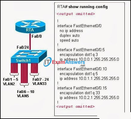
Hosts within each VLAN can communicate with each other.
Hosts in VLAN5 and VLAN33 are able to communicate with each other.
Hosts connected to Fa0/1 through Fa0/5 do not have connectivity to host in other VLANs.
Why are hosts connected to Fa0/1 through Fa0/5 unable to communicate with hosts in different VLANs?
- The router interface is shut down.
- The VLAN IDs do not match the subinterface numbers.
- All of the subinterface addresses on the router are in the same subnet.
- The router was not configured to forward traffic for VLAN2.
- The physical interface, FastEthernet0/0, was not configured with an IP address.
Exam with this question: CCNA Exploration 3: ESwitching Chapter 6 Exam
Please login or Register to submit your answer