
14.9.11 Packet Tracer - Layer 2 VLAN Security Answers Version
Topology
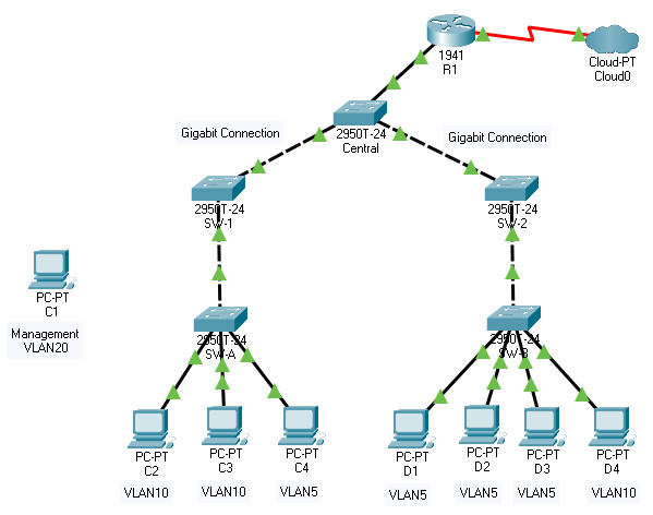
14.9.11 Packet Tracer – Layer 2 VLAN Security
Objectives
- Connect a new redundant link between switches.
- Enable trunking and configure security on the new trunk link between switches.
- Create a new management VLAN and attach a management PC to that VLAN.
- Implement an ACL to prevent outside users from accessing the management VLAN.
Background / Scenario
A company’s network is currently set up using two separate VLANs: VLAN 5 and VLAN 10. In addition, all trunk ports are configured with native VLAN 15. A network administrator wants to add a redundant link between switch SW-1 and SW-2. The link must have trunking enabled and all security requirements should be in place.
In addition, the network administrator wants to connect a management PC to switch SW-A. The administrator would like to enable the management PC to connect to all switches and the router but does not want any other devices to connect to the management PC or the switches. The administrator would like to create a new VLAN 20 for management purposes.
All devices have been preconfigured with:
- Enable secret password: ciscoenpa55
- Console password: ciscoconpa55
- SSH username and password: SSHadmin / ciscosshpa55
Instructions
Part 1: Verify Connectivity
Step 1: Verify connectivity between C2 (VLAN 10) and C3 (VLAN 10).
Step 2: Verify connectivity between C2 (VLAN 10) and D1 (VLAN 5).
Note: If using the simple PDU GUI packet, be sure to ping twice to allow for ARP.
Part 2: Create a Redundant Link Between SW-1 and SW-2
Step 1: Connect SW-1 and SW-2.
Using a crossover cable, connect port F0/23 on SW-1 to port F0/23 on SW-2.
Step 2: Enable trunking, including all trunk security mechanisms on the link between SW-1 and SW-2.
Trunking has already been configured on all pre-existing trunk interfaces. The new link must be configured for trunking, including all trunk security mechanisms. On both SW-1 and SW-2, set the port to trunk, assign native VLAN 15 to the trunk port, and disable auto-negotiation.
SW-1(config)# interface f0/23

SW-1(config-if)# switchport mode trunk

SW-1(config-if)# switchport trunk native vlan 15

SW-1(config-if)# switchport nonegotiate

SW-1(config-if)# no shutdown

SW-2(config)# interface f0/23

SW-2(config-if)# switchport mode trunk

SW-2(config-if)# switchport trunk native vlan 15

SW-2(config-if)# switchport nonegotiate

SW-2(config-if)# no shutdown
Part 3: Enable VLAN 20 as a Management VLAN
The network administrator wants to access all switch and routing devices using a management PC. For security purposes, the administrator wants to ensure that all managed devices are on a separate VLAN.
Step 1: Enable a management VLAN (VLAN 20) on SW-A.
a. Enable VLAN 20 on SW-A.
SW-A(config)# vlan 20

SW-A(config-vlan)# exit
b. Create an interface VLAN 20 and assign an IP address within the 192.168.20.0/24 network.
SW-A(config)# interface vlan 20

SW-A(config-if)# ip address 192.168.20.1 255.255.255.0
Step 2: Enable the same management VLAN on all other switches.
a. Create the management VLAN on all switches: SW-B, SW-1, SW-2, and Central.
SW-B(config)# vlan 20

SW-B(config-vlan)# exit

SW-1(config)# vlan 20

SW-1(config-vlan)# exit

SW-2(config)# vlan 20

SW-2(config-vlan)# exit

Central(config)# vlan 20

Central(config-vlan)# exit
b. Create an interface VLAN 20 on all switches and assign an IP address within the 192.168.20.0/24 network.
SW-B(config)# interface vlan 20

SW-B(config-if)# ip address 192.168.20.2 255.255.255.0

SW-1(config)# interface vlan 20

SW-1(config-if)# ip address 192.168.20.3 255.255.255.0

SW-2(config)# interface vlan 20

SW-2(config-if)# ip address 192.168.20.4 255.255.255.0

Central(config)# interface vlan 20

Central(config-if)# ip address 192.168.20.5 255.255.255.0
Step 3: Connect and configure the management PC.
Connect the management PC to SW-A port F0/1 and ensure that it is assigned an available IP address within the 192.168.20.0/24 network.
Step 4: On SW-A, ensure the management PC is part of VLAN 20.
Interface F0/1 must be part of VLAN 20.
SW-A(config)# interface f0/1

SW-A(config-if)# switchport access vlan 20

SW-A(config-if)# no shutdown
Step 5: Verify connectivity of the management PC to all switches.
The management PC should be able to ping SW-A, SW-B, SW-1, SW-2, and Central.
Part 4: Enable the Management PC to Access Router R1
Step 1: Enable a new subinterface on router R1.
a. Create subinterface g0/0.3 and set encapsulation to dot1q 20 to account for VLAN 20.
R1(config)# interface g0/0.3

R1(config-subif)# encapsulation dot1q 20
b. Assign an IP address within the 192.168.20.0/24 network.
R1(config)# interface g0/0.3

R1(config-subif)# ip address 192.168.20.100 255.255.255.0
Step 2: Verify connectivity between the management PC and R1.
Be sure to configure the default gateway on the management PC to allow for connectivity.
Step 3: Enable security.
While the management PC must be able to access the router, no other PC should be able to access the management VLAN.
a. Create an ACL that allows only the Management PC to access the router.
Example: (may vary from student configuration)
R1(config)# access-list 101 deny ip any 192.168.20.0 0.0.0.255

R1(config)# access-list 101 permit ip any any

R1(config)# access-list 102 permit ip host 192.168.20.50 any
b. Apply the ACL to the proper interface(s).
Example: (may vary from student configuration)
R1(config)# interface g0/0.1

R1(config-subif)# ip access-group 101 in

R1(config-subif)# interface g0/0.2

R1(config-subif)# ip access-group 101 in

R1(config-subif)# line vty 0 4

R1(config-line)# access-class 102 in
Note: Access list 102 is used to only allow the Management PC (192.168.20.50 in this example) to access the router. This prevents an IP address change to bypass the ACL.
Note: There are multiple ways in which an ACL can be created to accomplish the necessary security. For this reason, grading on this portion of the activity is based on the correct connectivity requirements. The management PC must be able to connect to all switches and the router. All other PCs should not be able to connect to any devices within the management VLAN.
Step 4: Verify security.
a. Verify only the Management PC can access the router. Use SSH to access R1 with username SSHadmin and password ciscosshpa55.
PC> ssh -l SSHadmin 192.168.20.100
b. From the management PC, ping SW-A, SW-B, and R1.
Question:
Were the pings successful? Explain.
The pings should have been successful because all devices within the 192.168.20.0 network should be able to ping one another. Devices within VLAN20 are not required to route through the router.
c. From D1, ping the management PC. Were the pings successful? Explain.
The ping should have failed because for a device within a different VLAN to successfully ping a device within VLAN20, it must be routed. The router has an ACL that prevents all packets from accessing the 192.168.20.0 network.
Step 5: Check results.
Your completion percentage should be 100%. Click Check Results to view feedback and verification of which required components have been completed.
If all components appear to be correct and the activity still shows incomplete, it could be due to the connectivity tests that verify the ACL operation.
Device Configs - Final
SWITCH SW-1
! ==============================================================
!--- 14.9.11 Packet Tracer - Layer 2 VLAN Security
!--- ANSWER SCRIPT FOR SWITCH SW-1
!--- Usage: copy this whole file and paste it into the SW-1 terminal (start at the SW-1> prompt). Every line beginning with "!" is a comment; IOS ignores it, so pasting a comment by accident is harmless.
! ==============================================================

enable
configure terminal

! --------------------------------------------------------------
!--- Part 1: Configure the New Redundant Trunk Link to SW-2 (F0/23).
! --------------------------------------------------------------

!--- Set the port to trunk mode.
interface fastethernet 0/23
 switchport mode trunk

!--- Assign native VLAN 15, matching every other pre-existing trunk in the network.
 switchport trunk native vlan 15

!--- Disable DTP negotiation on this trunk — a trunk security best practice that prevents an attacker from
!--- negotiating trunking on a port that shouldn't need to.
 switchport nonegotiate

!--- Bring the new physical link up.
 no shutdown
 exit

! --------------------------------------------------------------
!--- Part 2: Create and Address the Management VLAN (VLAN 20).
! --------------------------------------------------------------

!--- Create VLAN 20 on this switch.
vlan 20
 exit

!--- Assign SW-1's management IP within 192.168.20.0/24.
interface vlan 20
 ip address 192.168.20.3 255.255.255.0
 exit

end

! --------------------------------------------------------------
!--- Save the configuration to NVRAM. (Press Enter when prompted for the destination filename.)
! --------------------------------------------------------------
copy running-config startup-config


! ==============================================================
!--- Verification:
!---   show interfaces fastethernet 0/23 switchport -> confirms trunk mode, native VLAN 15, negotiation off
!---   show vlan brief                    -> confirms VLAN 20 exists
!---   show interfaces vlan 20            -> confirms 192.168.20.3/24 and the interface is up
!---   ping 192.168.20.1 (from SW-1)      -> confirms reachability to the management PC's switch (SW-A)
! ==============================================================
SWITCH SW-2
! ==============================================================
!--- 14.9.11 Packet Tracer - Layer 2 VLAN Security
!--- ANSWER SCRIPT FOR SWITCH SW-2
!--- Usage: copy this whole file and paste it into the SW-2 terminal (start at the SW-2> prompt). Every line beginning with "!" is a comment; IOS ignores it, so pasting a comment by accident is harmless.
! ==============================================================

enable
configure terminal

! --------------------------------------------------------------
!--- Part 1: Configure the New Redundant Trunk Link to SW-1 (F0/23).
! --------------------------------------------------------------

!--- Set the port to trunk mode.
interface fastethernet 0/23
 switchport mode trunk

!--- Assign native VLAN 15, matching every other pre-existing trunk in the network.
 switchport trunk native vlan 15

!--- Disable DTP negotiation on this trunk — a trunk security best practice that prevents an attacker from
!--- negotiating trunking on a port that shouldn't need to.
 switchport nonegotiate

!--- Bring the new physical link up.
 no shutdown
 exit

! --------------------------------------------------------------
!--- Part 2: Create and Address the Management VLAN (VLAN 20).
! --------------------------------------------------------------

!--- Create VLAN 20 on this switch.
vlan 20
 exit

!--- Assign SW-2's management IP within 192.168.20.0/24.
interface vlan 20
 ip address 192.168.20.4 255.255.255.0
 exit

end

! --------------------------------------------------------------
!--- Save the configuration to NVRAM. (Press Enter when prompted for the destination filename.)
! --------------------------------------------------------------
copy running-config startup-config


! ==============================================================
!--- Verification:
!---   show interfaces fastethernet 0/23 switchport -> confirms trunk mode, native VLAN 15, negotiation off
!---   show vlan brief                    -> confirms VLAN 20 exists
!---   show interfaces vlan 20            -> confirms 192.168.20.4/24 and the interface is up
!---   ping 192.168.20.1 (from SW-2)      -> confirms reachability to the management PC's switch (SW-A)
! ==============================================================
SWITCH SW-A
! ==============================================================
!--- 14.9.11 Packet Tracer - Layer 2 VLAN Security
!--- ANSWER SCRIPT FOR SWITCH SW-A
!--- Usage: copy this whole file and paste it into the SW-A terminal (start at the SW-A> prompt). Every line beginning with "!" is a comment; IOS ignores it, so pasting a comment by accident is harmless.
! ==============================================================

enable
configure terminal

! --------------------------------------------------------------
!--- Part 1: Create and Address the Management VLAN (VLAN 20).
! --------------------------------------------------------------

!--- Create VLAN 20 on this switch.
vlan 20
 exit

!--- Assign SW-A's management IP within 192.168.20.0/24.
interface vlan 20
 ip address 192.168.20.1 255.255.255.0
 exit

! --------------------------------------------------------------
!--- Part 2: Connect the Management PC to VLAN 20.
! --------------------------------------------------------------

!--- Move F0/1 (the management PC's access port) into VLAN 20.
interface fastethernet 0/1
 switchport access vlan 20
 no shutdown
 exit

end

! --------------------------------------------------------------
!--- Save the configuration to NVRAM. (Press Enter when prompted for the destination filename.)
! --------------------------------------------------------------
copy running-config startup-config


! ==============================================================
!--- Verification:
!---   show vlan brief                    -> confirms VLAN 20 exists and F0/1 is a member
!---   show interfaces vlan 20            -> confirms 192.168.20.1/24 and the interface is up
!---   (Management PC) ping SW-A, SW-B, SW-1, SW-2, Central (all 192.168.20.x) -> all succeed
!--- Note: the management PC connected to F0/1 needs a static IP in 192.168.20.0/24 (e.g. .50, matching
!--- the ACL example on R1) and, once R1's subinterface is up, a default gateway of 192.168.20.100.
! ==============================================================
SWITCH SW-B
! ==============================================================
!--- 14.9.11 Packet Tracer - Layer 2 VLAN Security
!--- ANSWER SCRIPT FOR SWITCH SW-B
!--- Usage: copy this whole file and paste it into the SW-B terminal (start at the SW-B> prompt). Every line beginning with "!" is a comment; IOS ignores it, so pasting a comment by accident is harmless.
! ==============================================================

enable
configure terminal

! --------------------------------------------------------------
!--- Part 1: Create and Address the Management VLAN (VLAN 20).
! --------------------------------------------------------------

!--- Create VLAN 20 on this switch.
vlan 20
 exit

!--- Assign SW-B's management IP within 192.168.20.0/24.
interface vlan 20
 ip address 192.168.20.2 255.255.255.0
 exit

end

! --------------------------------------------------------------
!--- Save the configuration to NVRAM. (Press Enter when prompted for the destination filename.)
! --------------------------------------------------------------
copy running-config startup-config


! ==============================================================
!--- Verification:
!---   show vlan brief                    -> confirms VLAN 20 exists
!---   show interfaces vlan 20            -> confirms 192.168.20.2/24 and the interface is up
!---   ping 192.168.20.1 (from SW-B)      -> confirms reachability to the management PC's switch (SW-A)
!--- Note: unlike SW-A, no access port on SW-B is moved into VLAN 20 — the management PC only connects
!--- through SW-A's F0/1; SW-B just needs a VLAN 20 SVI to be reachable for management.
! ==============================================================
SWITCH Central
! ==============================================================
!--- 14.9.11 Packet Tracer - Layer 2 VLAN Security
!--- ANSWER SCRIPT FOR SWITCH Central
!--- Usage: copy this whole file and paste it into the Central terminal (start at the Central> prompt). Every line beginning with "!" is a comment; IOS ignores it, so pasting a comment by accident is harmless.
! ==============================================================

enable
configure terminal

! --------------------------------------------------------------
!--- Part 1: Create and Address the Management VLAN (VLAN 20).
! --------------------------------------------------------------

!--- Create VLAN 20 on this switch.
vlan 20
 exit

!--- Assign Central's management IP within 192.168.20.0/24.
interface vlan 20
 ip address 192.168.20.5 255.255.255.0
 exit

end

! --------------------------------------------------------------
!--- Save the configuration to NVRAM. (Press Enter when prompted for the destination filename.)
! --------------------------------------------------------------
copy running-config startup-config


! ==============================================================
!--- Verification:
!---   show vlan brief                    -> confirms VLAN 20 exists
!---   show interfaces vlan 20            -> confirms 192.168.20.5/24 and the interface is up
!---   ping 192.168.20.1 (from Central)   -> confirms reachability to the management PC's switch (SW-A)
! ==============================================================
ROUTER R1
! ==============================================================
!--- 14.9.11 Packet Tracer - Layer 2 VLAN Security
!--- ANSWER SCRIPT FOR ROUTER R1
!--- Usage: copy this whole file and paste it into the R1 terminal (start at the R1> prompt). Every line beginning with "!" is a comment; IOS ignores it, so pasting a comment by accident is harmless.
!--- Note: subinterfaces GigabitEthernet0/0.1 (VLAN 5) and 0/0.2 (VLAN 10) are pre-existing from an earlier
!--- activity; this script only adds to them, it does not create them.
! ==============================================================

enable
configure terminal

! --------------------------------------------------------------
!--- Part 1: Create the Management VLAN Subinterface.
! --------------------------------------------------------------

!--- Create subinterface G0/0.3 for VLAN 20 and tag it with 802.1Q.
interface gigabitethernet 0/0.3
 encapsulation dot1q 20

!--- Assign R1's management IP, the default gateway for hosts on VLAN 20.
 ip address 192.168.20.100 255.255.255.0
 exit

! --------------------------------------------------------------
!--- Part 2: Define the ACLs That Protect the Management VLAN.
! --------------------------------------------------------------

!--- ACL 101: deny any traffic destined for the management network (192.168.20.0/24) — blocks VLAN5/VLAN10
!--- users from reaching management devices — then permit everything else so normal routing is unaffected.
access-list 101 deny ip any 192.168.20.0 0.0.0.255
access-list 101 permit ip any any

!--- ACL 102: permit only the management PC's own address for administrative (VTY) access to the router.
access-list 102 permit ip host 192.168.20.50 any

! --------------------------------------------------------------
!--- Part 3: Apply the ACLs to the Correct Interfaces.
! --------------------------------------------------------------

!--- Apply ACL 101 inbound on the VLAN 5 subinterface, blocking that network from reaching VLAN 20.
interface gigabitethernet 0/0.1
 ip access-group 101 in
 exit

!--- Apply ACL 101 inbound on the VLAN 10 subinterface, blocking that network from reaching VLAN 20.
interface gigabitethernet 0/0.2
 ip access-group 101 in
 exit

!--- Restrict VTY (SSH) login to only the management PC's address, via ACL 102.
line vty 0 4
 access-class 102 in
 exit

end

! --------------------------------------------------------------
!--- Save the configuration to NVRAM. (Press Enter when prompted for the destination filename.)
! --------------------------------------------------------------
copy running-config startup-config


! ==============================================================
!--- Verification:
!---   show ip interface brief                -> confirms G0/0.3 is up/up with 192.168.20.100
!---   show access-lists                      -> confirms ACL 101 (2 lines) and ACL 102 (1 line)
!---   show run | section interface Gig       -> confirms "ip access-group 101 in" on G0/0.1 and G0/0.2
!---   show run | section line vty            -> confirms "access-class 102 in"
!---   (Management PC, 192.168.20.50) ssh -l SSHadmin 192.168.20.100 -> succeeds
!---   (D1, VLAN 5) ping 192.168.20.50 (management PC)                -> fails (blocked by ACL 101 on G0/0.1)
!--- Note: this script reorders the lab's own Answer Script slightly — it defines ACL 101/102 BEFORE
!--- applying them to interfaces/VTY, instead of applying first and defining after. Both orders work in
!--- IOS (an empty ACL referenced by "ip access-group" simply matches nothing until statements are added),
!--- but defining first is the safer paste order and avoids a window where the interface briefly references
!--- a still-empty ACL.
!--- Note: per the lab's own text, "192.168.20.50" for the management PC and this exact ACL structure are
!--- one example — grading is based on the resulting connectivity behavior (PC reaches everything in
!--- 192.168.20.0/24 and the router; no other host reaches that network), not on matching these ACL numbers
!--- verbatim, so adapt the address if your management PC is assigned a different IP in the activity.
! ==============================================================


