
1.1.6 Packet Tracer Tutored Activity - Logical and Physical Mode Exploration
Objectives
- Investigate Devices in a Wiring Closet
- Connect End Devices to Networking Devices
- Install a Backup Router
- Configure a Hostname
Background / Scenario
The network model in this Packet Tracer Tutored Activity (PTTA) incorporates many of the technologies that you can master in Cisco Networking Academy courses. It represents a simplified version of how a small to medium-sized business network might look.
Most of the devices in the Seward Branch Office (top left) and Warrenton (bottom right) data center are already deployed and configured. You have just been hired to review the devices and networks deployed. It is not important that you understand everything you see and do in this activity. Feel free to explore the network and become familiar with the menus on your own. Hints will also appear after a certain amount of time. You can select a hint level with the slider bar in the bottom left hand corner.
Note: There are two way to look at a network in Packet Tracer. Logical mode shows you how devices are connected in the network. Physical mode shows you where the devices are located in the network. This activity opens in and focuses on Physical mode. Many of the Packet Tracer activities you encounter in Cisco Networking Academy courses will use Logical mode. You can switch between these modes at any time to compare the differences by clicking the Logical (Shift-L) and Physical (Shift-P) buttons. However, in other activities in this course you may be locked out of one mode or the other.
Click on the locations to explore the network. Become familiar with the network representations in both Logical and Physical modes. In Physical mode, navigate to other areas such as the Warrenton Data Center and Teleworker Home. The technologies used in these locations are discussed in greater detail in future courses.
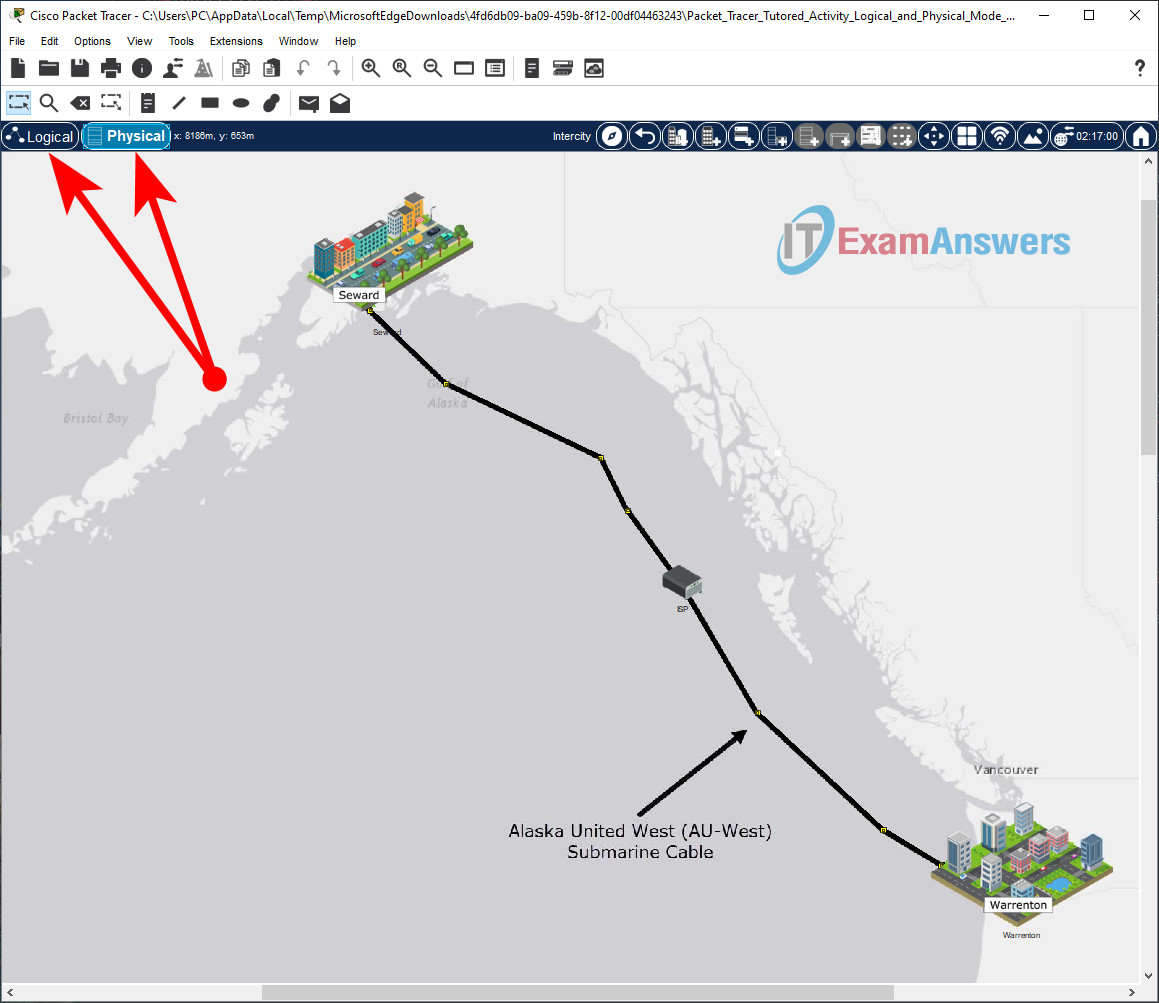
Most of the devices in the Seward branch office and Warrenton data center are already deployed and configured. You can explore the devices and networks. It is not important that you understand everything you see and do in this activity. Feel free to explore the network on your own. Hints will also appear after a certain amount of time. You can select a hint level with the slider bar in the bottom left hand corner. Answer the questions to the best of your ability.
You can switch between these modes at any time to compare the differences by clicking the Logical (Shift-L) and Physical (Shift-P) buttons.
For now, see what you can discover on your own. Don't worry about breaking anything. You can always reset the activity or close Packet Tracer and open a fresh copy to start exploring again.
When you are done with exploring and answering all the questions, click Next to continue.
In Physical Mode (Shift-P), what are the cities connected?
In Physical Mode (Shift-P), what is the name of the submarine cable?
In Logical Mode (Shift-L), what are the wireless devices in the Teleworker Home? (Hint: They are not connected with a solid black line.)
In Physical Mode (Shift-P), what facility can you enter in the Seward, Alaska location?
Which locations can you enter in the other city?
Investigate Devices in a Wiring Closet
In this step, you will navigate to the Branch Office wiring closet in Seward. You will also connect a PC to a switch using an Ethernet cable.
In the Intercity, click Seward. While in Seward, click the Branch Office and then click the Branch Office Wiring Closet.
Locate Seward on the map. Click to enter Seward.
You can change the zoom level on the map, press Ctrl (Cmd on macOS) and scroll with the mouse wheel or click View > Zoom and select the desired zoom level.

Connect PC_1 FastEthernet0 to an empty FastEthernet port on ALS2.
Notice that the wiring closet has a Rack, a Cable Pegboard, a Table, and a Shelf.
If you need to change the zoom level, press Ctrl (Cmd for macOS) and scroll with the mouse wheel or click View > Zoom and select the desired zoom level. Hover over a cable with your mouse to see what type of cable it is.

When the connection is established, the LED lights next to the Ethernet ports will be blinking green.

Connect End Devices to Networking Devices
PCs and laptops can also be connected to networking devices using a console cable or a USB cable. This connection provides management access. Management access is used to view and change device configurations.
In this step, you will connect a PC to a router using a console cable.
While in Physical mode, connect RS232 port on PC_1 to the Console port on the Edge_Router.
Select the Console cable (light blue cable) on the Cable Pegboard.

Install a Backup Router
Newer models of networking devices can be accessed for management configuration through a USB port. This is necessary because newer laptops and PCs typically do not include an RS232 port for console cable connections.
In this step, you will install and power up a new router in the Rack. You will also connect to this device via the USB console with a USB cable.
In Packet Tracer, an inventory of devices can be stored on the Shelf. These devices are powered off and can be previously configured and deployed to replace or add to the production devices on the Rack.
Install Backup_Router in the Rack and turn the power on.
Locate the Backup_Router on the 4th Shelf.
Select and drag the Backup_Router from the Shelf to an empty space on the Rack.

Install the Backup_Router and power on the Backup_Router. Right-click the Backup_Router. Select Inspect Rear to locate the power switch.

Connect Laptop_1 to the Backup_Router with a USB cable.
Select a black USB cable from the Cable Pegboard. Hover over the black cable to verify it is a USB cable.
Right-click the Backup_Router. Select Inspect Rear to locate the USB console port.
Click the USB console port on the Backup_Router to connect the USB cable.

Configure a Hostname
You have connected Laptop_1 to Backup_Router via a USB console cable. With the USB console connected, you will access the command line interface (CLI) of Backup_Router via terminal software and configure a hostname.
Every computer, including network devices, such as routers and switches, requires an operating system to function. The operating system allows the device hardware to function and provides an inteface for users to interact.
The Cisco Internetwork Operating System (IOS) is an operating system used in Cisco networking devices. It allows creation of configurations that customize the operation of network devices in different network environments. The CLI is accessible via the device console port using terminal software or remotely via Secure Shell (SSH). Network administrators use a computer to access the device console in order to create or modify the device configuation.
Network administrators typically assign names to networking devices. The host name is used to identify a device when accessing its operating system for configuration. To do this, you will use your console connection to the Backup_Router . After the hostname has been configured, the hostname appears as part of the IOS command prompt.
In this step, you will configure the hostname on Backup_Router .
On Laptop_1 , access the Desktop tab and click Terminal. The Terminal Configuration is already set with the necessary port configuration, and should be used with its default settings. Click OK to initiate the terminal connection.
Click Laptop_1 on the Table.

Click Desktop.
Click Terminal and click OK.


You are now at the command line for Backup_Router and should see the following output from the router.
[output omitted]
cisco ISR4331/K9 (1RU) processor with 1795999K/6147K bytes of memory.
Processor board ID FLM232010G0
3 Gigabit Ethernet interfaces
2 Serial interfaces
32768K bytes of non-volatile configuration memory.
4194304K bytes of physical memory.
3207167K bytes of flash memory at bootflash:.
0K bytes of WebUI ODM Files at webui:.
Answer no to the question and then press ENTER to reach the Router> command prompt.
         --- System Configuration Dialog ---
Would you like to enter the initial configuration dialog? [yes/no]: no

Enter the following commands (in bold) to name the router Edge_Router_Backup. Note that the hostname must match this value exactly.
Router> enable
Router# configure terminal
Router(config)# hostname Edge_Router_Backup
Edge_Router_Backup(config)# end
Reflection Question Answers
Let's reflect on what you just accomplished.
Besides Ethernet and the console cables, what are other ways to connect devices?
What is the difference between the wiring closet Rack, Table, and Shelf?
How does Logical Mode differ from Physical Mode?

