2.1.2.3 Lab – Blinking an LED Using Blockly Objectives Answers
- Part 1: Open Packet Tracer and Examine Blockly Program for LED Blinking
- Part 2: Control a RGB LED using Blockly
Background
Blockly is a visual programming language that lets users create programs by connecting blocks, that represent different logic language structures, rather than by writing the actual code. Blockly runs within a web browser and can translate the visually created program as JavaScript, PHP, or Python. In this lab, you will use Blockly to examine Blockly programming and to control an LED.
Scenario
Using Blockly programming to control an IoT object LED. In this lab, Cisco Packet Tracer is used as it provides Blockly support with IoT objects.
Required Resources
- Cisco Packet Tracer 7.1.1 and above is installed and available.
Instructions
Part 1: Launch Cisco Packet Tracer (PT) and Use Blockly
In Part 1, you will access the Cisco Packet Tracer program and examine LED control using Blockly programming.
Step 1: Launch Packet Tracer.
a. Double click the Cisco Packet Tracer icon to open the PT program.

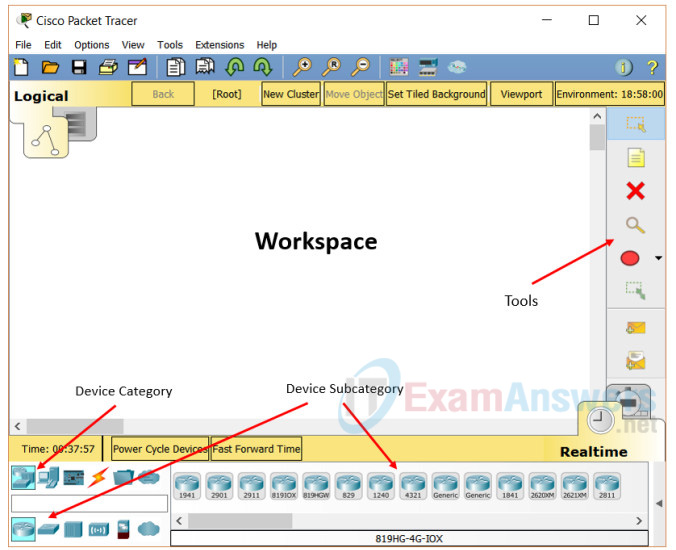
b. The user interface is shown.
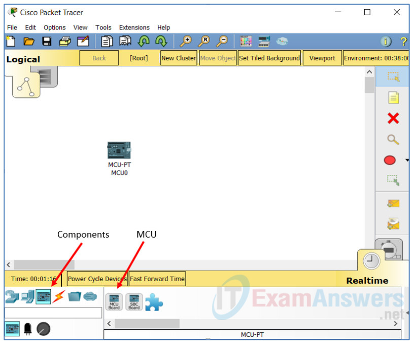
c. Click on the Components category, then click MCU Board and drag it to the workspace.
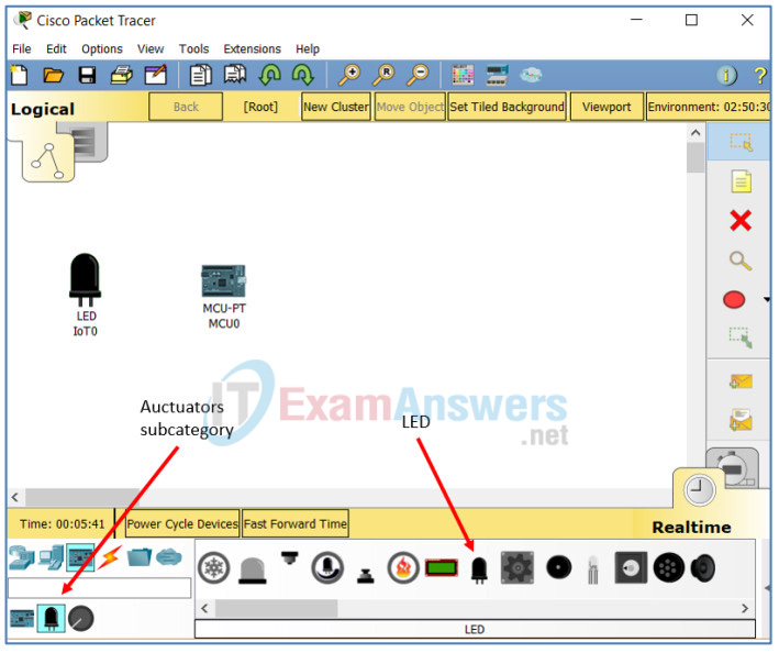
d. Click the subcategory Actuators, select LED and drag it to the workspace.
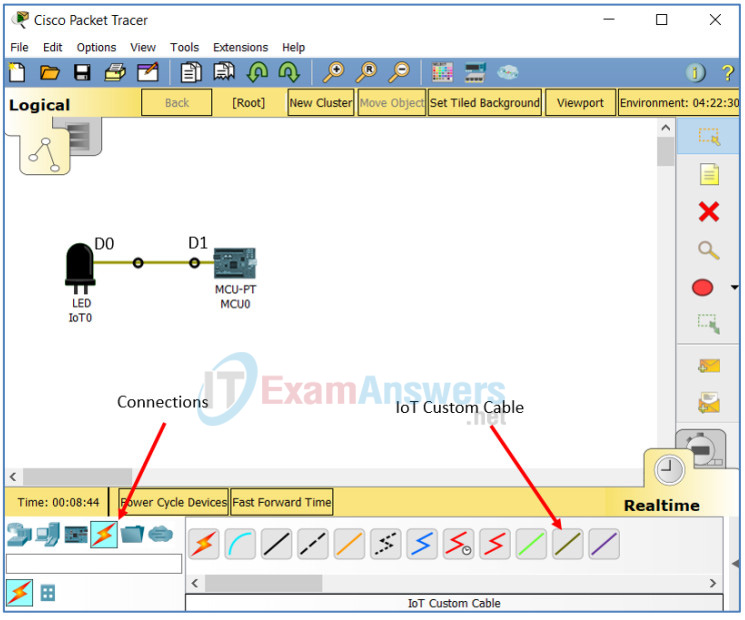
e. Click the Connections category, select IoT Custom Cable to link MCU at port D1 and LED at port D0.
f. Double click the MCU. Its configuration window displays.

g. Click the Programming tab. (If you do not see the Programming tab, click the Advanced button at the lower right corner.)

Step 2: Examine a prebuilt Blockly program
a. Under the note No Project Opened, click New. In the Create Project window, enter Blinking LED as the project name. In the Template dropdown menu, select Blink – Visual.
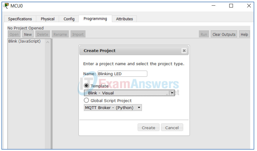
b. Click Create.

c. Double-click main.visual. The prebuilt Blockly program displays.
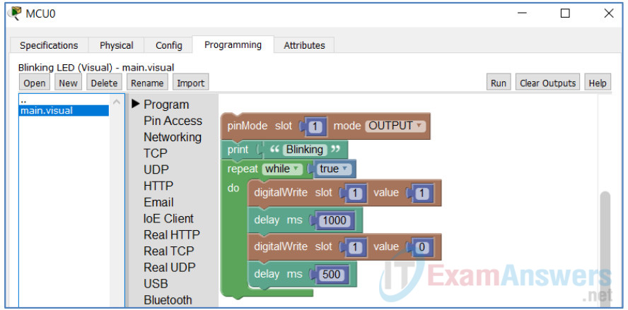
d. Click Run. Does the LED blink?
No
e. Click Stop, and change the Value field of the first digitalWrite block to 1023.
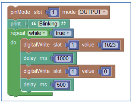
f. Click Run, does the LED blink?
Yes
Why was it not blinking when the value was not set to 1023?
The digital out takes the value 1023 as “HIGH”, and turns on the output current
g. Click the LED and study its specification.
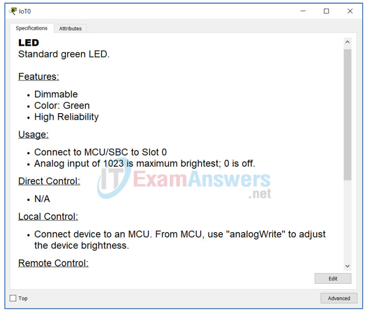
h. It indicates that we can use “analogWrite” to adjust the device brightness. Click the first digitalWrite block and press Delete. Expand the Pin Access group and drag an analogWrite block to to where the digitalWrite block was. Do the same for the second digitalWrite block.
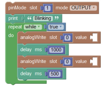
i. Change the slot value for each of the analogWrite blocks to 1. Right-click the small block with the value of zero (0) and click duplicate. Drag the new block into the empty space next to value. Do the same for the second analogWrite slot.
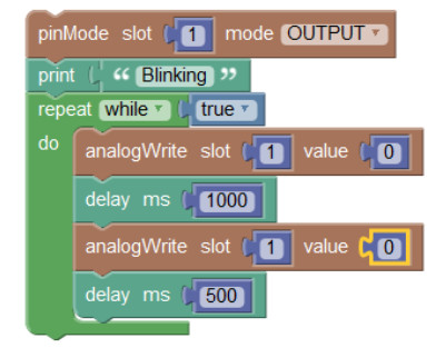
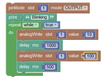
j. Change the values of the first and second analogWrite blocks and observe the different LED brightness levels.
Part 2: Control an RGB LED using Blockly
In Part 2, you used Blockly to control an RGB LED. An RGB can display different colors with the combination of red, green, and blue.
Step 1: Add an MCU and an RGB LED.
In Step 1, you add another MCU board and a RGB LED into the workspace.
a. Click the subcategory Actuators, select RGB LED and drag it to the workspace. Add another MCU board.
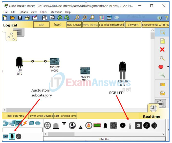
b. Click the Connections category, select three IoT Custom Cables to link MCU and RGB LED.
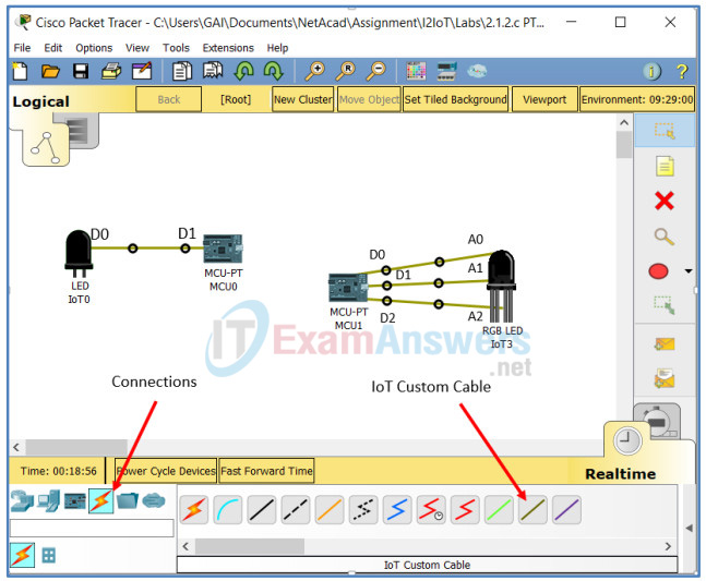
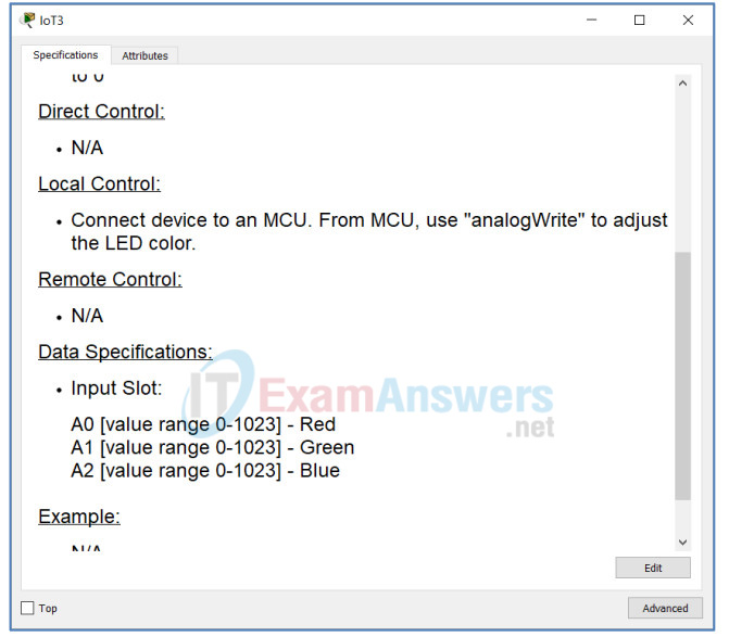
c. Click RGB LED and review its specification. Note different pin inputs represent different colors.
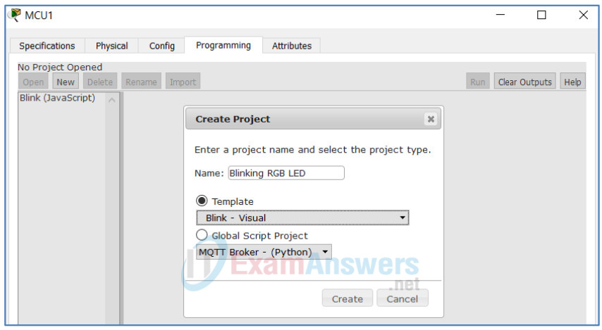
d. Open the prebuilt Blockly program. Click MCU -> Programming. Under the note No Project Opened, click New. In the Create Project window, enter Blinking RGB LED as the project name. In the Template dropdown menu, select Blink – Visual.
e. Click Create. Double-click main.visual. The prebuilt Blockly program displays.
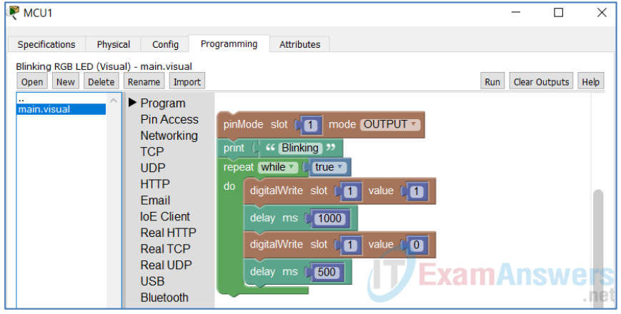
Step 2: Modify the Blockly program
a. Expand Pin Access group, and add two more pinMode blocks to set three slots as OUTPUT (from MCB to send a signal to RGB LED).
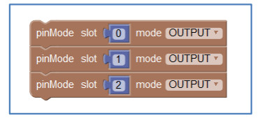
b. From the Pin Access group, select analogWrite blocks to replace digitalWrite blocks. Also, add a few print blocks.
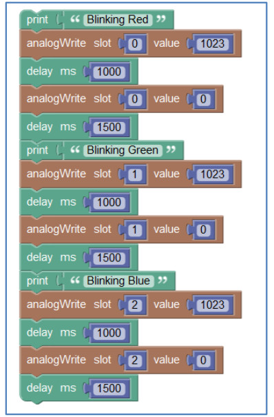
c. The final program is as follows:
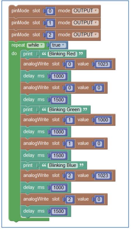
d. Run the program. The LED should display RED, GREEN, and BLUE in sequence.
Challenge
Modify the program to show a combined color from all three inputs with different, randomly generated values for each slot.
