10.4.4 Lab – Build a Switch and Router Network
Topology

Addressing Table
| Device | Interface | IP Address / Prefix | Default Gateway |
|---|---|---|---|
| R1 | G0/0/0 | 192.168.0.1 /24 | N/A |
| 2001:db8:acad::1/64 | |||
| fe80::1 | |||
| G0/0/1 | 192.168.1.1 /24 | N/A | |
| 200:db8:acad:1::1/64 | |||
| fe80::1 | |||
| S1 | VLAN 1 | 192.168.1.2 /24 | 192.168.1.1 |
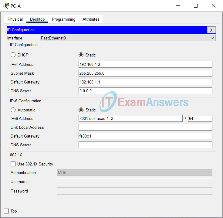
| PC-A | NIC | 192.168.1.3 /24 | 192.168.1.1 |
| 2001:db8:acad:1::3/64 | fe80::1 | ||
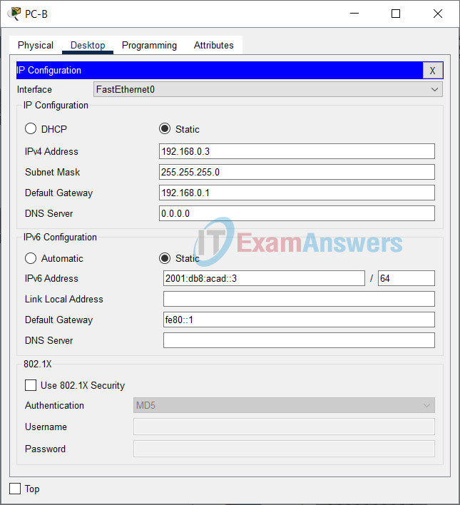
| PC-B | NIC | 192.168.0.3 /24 | 192.168.0.1 |
| 2001:db8:acad::3/64 | fe80::1 |
Objectives
- Part 1: Set Up the Topology and Initialize Devices
- Part 2: Configure Devices and Verify Connectivity
Background / Scenario
This is a comprehensive lab to review previously covered IOS commands. In this lab, you will cable the equipment as shown in the topology diagram. You will then configure the devices to match the addressing table. After the configurations have been saved, you will verify your configurations by testing for network connectivity.
After the devices have been configured and network connectivity has been verified, you will use IOS commands to retrieve information from the devices to answer questions about your network equipment.
This lab provides minimal assistance with the actual commands necessary to configure the router. Test your knowledge by trying to configure the devices without referring to the content or previous activities.
Note: The routers used with CCNA hands-on labs are Cisco 4221 with Cisco IOS XE Release 16.9.4 (universalk9 image). The switches used in the labs are Cisco Catalyst 2960s with Cisco IOS Release 15.2(2) (lanbasek9 image). Other routers, switches, and Cisco IOS versions can be used. Depending on the model and Cisco IOS version, the commands available and the output produced might vary from what is shown in the labs. Refer to the Router Interface Summary Table at the end of the lab for the correct interface identifiers.
Note: Ensure that the routers and switches have been erased and have no startup configurations. Consult with your instructor for the procedure to initialize and reload a router and switch.
The default bias template used by the Switch Database Manager (SDM) does not provide IPv6 address capabilities. Verify that SDM is using either the dual-ipv4-and-ipv6 template or the lanbase-routing template. The new template will be used after reboot even if the configuration is not saved.
S1# show sdm prefer
Use the following commands to assign the dual-ipv4-and-ipv6 template as the default SDM template.
S1# configure terminal
S1(config)# sdm prefer dual-ipv4-and-ipv6 default
S1(config)# end
S1# reload
Required Resources
- 1 Router (Cisco 4221 with Cisco IOS XE Release 16.9.4 universal image or comparable)
- 1 Switch (Cisco 2960 with Cisco IOS Release 15.2(2) lanbasek9 image or comparable)
- 2 PCs (Windows with a terminal emulation program, such as Tera Term)
- Console cables to configure the Cisco IOS devices via the console ports
- Ethernet cables as shown in the topology
Note: The Gigabit Ethernet interfaces on Cisco 4221 routers are autosensing and an Ethernet straight-through cable may be used between the router and PC-B. If using another model Cisco router, it may be necessary to use an Ethernet crossover cable.
Instructor Note: A USB driver must be installed prior to connecting a Microsoft Windows-based PC to a Cisco IOS device with a USB cable. The driver can be found on www.cisco.com with the related Cisco IOS device. The USB driver can be downloaded from the following link:
Instructor Note: You must have a valid Cisco Connection Online (CCO) account to download the USB driver file.
Instructions
Part 1: Set Up Topology and Initialize Devices
Step 1: Cable the network as shown in the topology.
a. Attach the devices shown in the topology diagram, and cable, as necessary.
b. Power on all the devices in the topology.
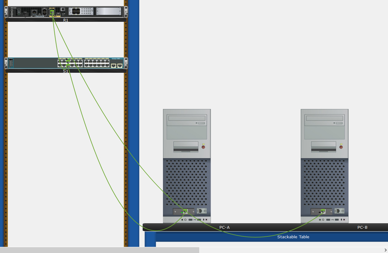
Step 2: Initialize and reload the router and switch.
On Switch:
Switch# delete flash:vlan.dat
Switch# erase startup-config
Switch# reload

On Router:
Router# erase startup-config
Router# reload
If configuration files were previously saved on the router and switch, initialize and reload these devices back to their default configurations.
Part 2: Configure Devices and Verify Connectivity
In Part 2, you will set up the network topology and configure basic settings, such as the interface IP addresses, device access, and passwords. Refer to the Error! Reference source not found. and Error! Reference source not found. at the beginning of this lab for device names and address information.
Step 1: Assign static IP information to the PC interfaces.
a. Configure the IP address, subnet mask, and default gateway settings on PC-A.
b. Configure the IP address, subnet mask, and default gateway settings on PC-B.
c. Ping PC-B from a command prompt window on PC-A.
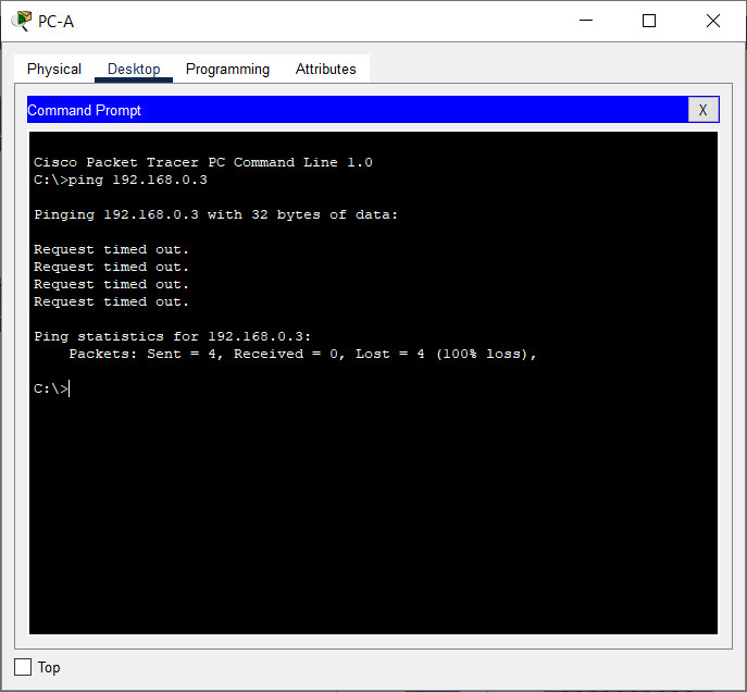
Note: If pings are not successful, the Windows Firewall may need to be turned off.
Why were the pings not successful?
The router interfaces (default gateways) have not been configured yet so Layer 3 traffic is not being routed between subnets.
Step 2: Configure the router.
a. Console into the router and enable privileged EXEC mode.
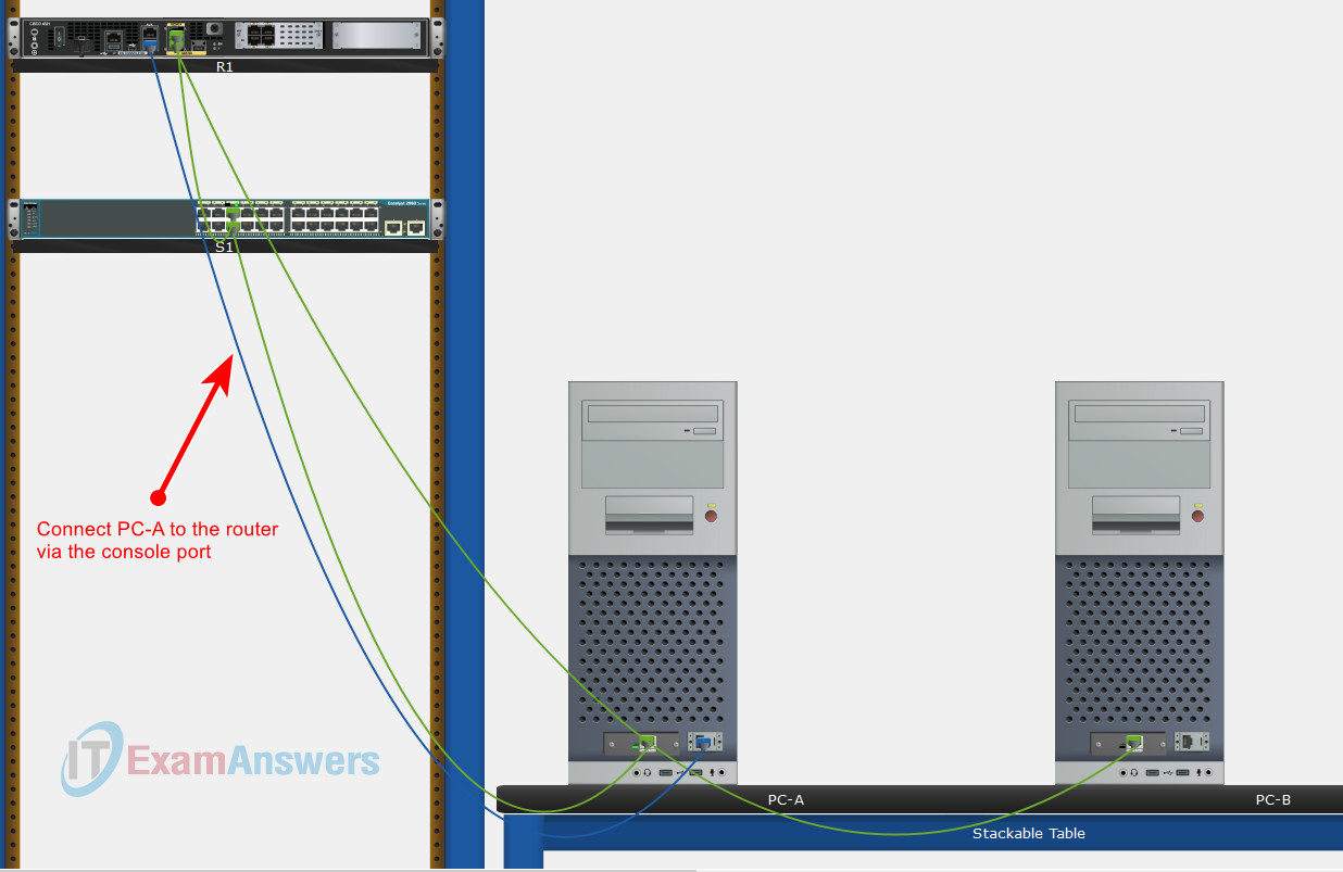
Router> enable
b. Enter configuration mode.
Router# config terminal
c. Assign a device name to the router.
Router(config)# hostname R1
d. Disable DNS lookup to prevent the router from attempting to translate incorrectly entered commands as though they were host names.
R1(config)# no ip domain-lookup
e. Assign class as the privileged EXEC encrypted password.
R1(config)# enable secret class
f. Assign cisco as the console password and enable login.
R1(config)# line console 0
R1(config-line)# password cisco
R1(config-line)# login
g. Assign cisco as the VTY password and enable login.
R1(config)# line vty 0 4
R1(config-line)# password cisco
R1(config-line)# login
h. Encrypt the plaintext passwords.
R1(config)# service password-encryption
i. Create a banner that warns anyone accessing the device that unauthorized access is prohibited.
R1(config)# banner motd $ Authorized Users Only! $
j. Configure and activate both interfaces on the router.
R1(config)# interface g0/0/0
R1(config-if)# ip address 192.168.0.1 255.255.255.0
R1(config-if)# ipv6 address 2001:db8:acad::1/64
R1(config-if)# ipv6 address FE80::1 link-local
R1(config-if)# no shutdown
R1(config-if)# exit
R1(config)# interface g0/0/1
R1(config-if)# ip address 192.168.1.1 255.255.255.0
R1(config-if)# ipv6 address 2001:db8:acad:1::1/64
R1(config-if)# ipv6 address fe80::1 link-local
R1(config-if)# no shutdown
R1(config-if)# exit
k. Configure an interface description for each interface indicating which device is connected to it.
R1(config)# interface g0/0/1
R1(config-if)# description Connected to F0/5 on S1
R1(config-if)# exit
R1(config)# interface g0/0/0
R1(config-if)# description Connected to Host PC-B
R1(config-if)# exit
l. To enable IPv6 routing, enter the command ipv6 unicast-routing.
R1(config)# ipv6 unicast-routing
m. Save the running configuration to the startup configuration file.
R1(config)# exit
R1# copy running-config startup-config
n. Set the clock on the router.
R1# clock set 15:30:00 27 Aug 2019
Note: Use the question mark (?) to help with the correct sequence of parameters needed to execute this command.
o. Ping PC-B from a command prompt window on PC-A.
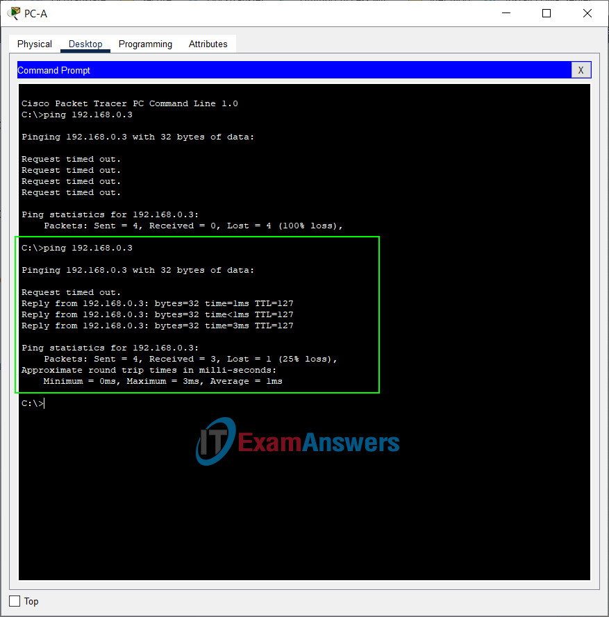
Note: If pings are not successful, the Windows Firewall may need to be turned off.
Were the pings successful? Explain.
Yes. The router is routing the ping traffic across the two subnets. The default settings for the 2960 switch will automatically turn up the interfaces that are connected to devices.
Step 3: Configure the switch.
In this step, you will configure the hostname, the VLAN 1 interface and its default gateway.
a. Console into the switch and enable privileged EXEC mode.
Right-click on switch S1, select “Inspect Rear” to display S1 console port.
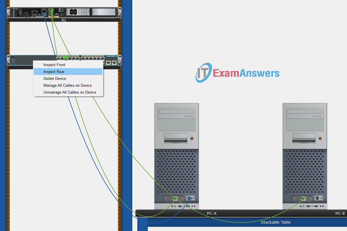
Use the console cable to connect PC-B to the switch through the console port.
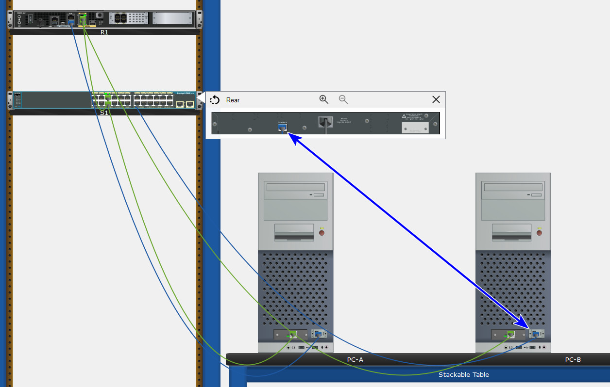
Switch> enable
b. Enter configuration mode.
Switch# config terminal
c. Assign a device name to the switch.
Switch(config)# hostname S1
d. Disable DNS lookup to prevent the router from attempting to translate incorrectly entered commands as though they were host names.
S1(config)# no ip domain-lookup
e. Configure and activate the VLAN interface on the switch S1.
S1(config)# interface vlan 1
S1(config-if)# ip address 192.168.1.2 255.255.255.0
S1(config-if)# no shutdown
S1(config-if)# exit
f. Configure the default gateway for the switch S1.
S1(config)# ip default-gateway 192.168.1.1
S1(config-if)# end
g. Save the running configuration to the startup configuration file.
S1# copy running-config startup-config
Step 4: Verify connectivity end-to-end connectivity.
a. From PC-A, ping PC-B.
b. From S1, ping PC-B.
All the pings should be successful.
Part 3: Display Device Information
In Part 3, you will use show commands to retrieve interface and routing information from the router and switch.
Step 1: Display the routing table on the router.
a. Use the show ip route command on the router R1 to answer the following questions.
R1# show ip route
Codes: L - local, C - connected, S - static, R - RIP, M - mobile, B - BGP
       D - EIGRP, EX - EIGRP external, O - OSPF, IA - OSPF inter area
       N1 - OSPF NSSA external type 1, N2 - OSPF NSSA external type 2
       E1 - OSPF external type 1, E2 - OSPF external type 2
       i - IS-IS, su - IS-IS summary, L1 - IS-IS level-1, L2 - IS-IS level-2
       ia - IS-IS inter area, * - candidate default, U - per-user static route
       o - ODR, P - periodic downloaded static route, H - NHRP, l - LISP
       + - replicated route, % - next hop override

Gateway of last resort is not set

      192.168.0.0/24 is variably subnetted, 2 subnets, 2 masks
C        192.168.0.0/24 is directly connected, GigabitEthernet0/0/0
L        192.168.0.1/32 is directly connected, GigabitEthernet0/0/0
      192.168.1.0/24 is variably subnetted, 2 subnets, 2 masks
C        192.168.1.0/24 is directly connected, GigabitEthernet0/0/1
L        192.168.1.1/32 is directly connected, GigabitEthernet0/0/1
What code is used in the routing table to indicate a directly connected network?
The C designates a directly connected subnet. An L designates a local interface. Both answers are correct.
How many route entries are coded with a C code in the routing table?
2
What interface types are associated to the C coded routes?
Answers may vary depending of router type, but on the 4221 the correct answer is G0/0/0 and G0/0/1.
b. Use the show ipv6 route command on router R1 to display the IPv6 routes.
R1# show ipv6 route
IPv6 Routing Table - default - 5 entries
Codes: C - Connected, L - Local, S - Static, U - Per-user Static route
       B - BGP, R - RIP, H - NHRP, I1 - ISIS L1
       I2 - ISIS L2, IA - ISIS interarea, IS - ISIS summary, D - EIGRP
       EX - EIGRP external, ND - ND Default, NDp - ND Prefix, DCE - Destination
       NDr - Redirect, RL - RPL, O - OSPF Intra, OI - OSPF Inter
       OE1 - OSPF ext 1, OE2 - OSPF ext 2, ON1 - OSPF NSSA ext 1
       ON2 - OSPF NSSA ext 2, la - LISP alt, lr - LISP site-registrations
       ld - LISP dyn-eid, lA - LISP away, le - LISP extranet-policy
       a - Application
C   2001:DB8:ACAD::/64 [0/0]
     via GigabitEthernet0/0/0, directly connected
L   2001:DB8:ACAD::1/128 [0/0]
     via GigabitEthernet0/0/0, receive
C   2001:DB8:ACAD:1::/64 [0/0]
     via GigabitEthernet0/0/1, directly connected
L   2001:DB8:ACAD:1::1/128 [0/0]
     via GigabitEthernet0/0/1, receive
L   FF00::/8 [0/0]
     via Null0, receive
Step 2: Display interface information on the router R1.
a. Use the show ip interface g0/0/1 to answer the following questions.
R1# show ip interfaces g0/0/1
GigabitEthernet0/0/1 is up, line protocol is up
  Hardware is ISR4321-2x1GE, address is a0e0.af0d.e141 (bia a0e0.af0d.e141)
  Description: Connectd to F0/5 on S1
  Internet address is 192.168.1.1/24
  MTU 1500 bytes, BW 100000 Kbit/sec, DLY 100 usec,
     reliability 255/255, txload 1/255, rxload 1/255
  Encapsulation ARPA, loopback not set
  Keepalive not supported
  Full Duplex, 100Mbps, link type is auto, media type is RJ45
  output flow-control is off, input flow-control is off
  ARP type: ARPA, ARP Timeout 04:00:00
  Last input 00:00:00, output 00:00:19, output hang never
  Last clearing of "show interface" counters never
  Input queue: 0/375/0/0 (size/max/drops/flushes); Total output drops: 0
  Queueing strategy: fifo
  Output queue: 0/40 (size/max)
  5 minute input rate 0 bits/sec, 0 packets/sec
  5 minute output rate 0 bits/sec, 0 packets/sec
     4579 packets input, 637737 bytes, 0 no buffer
     Received 1092 broadcasts (0 IP multicasts)
     0 runts, 0 giants, 0 throttles
     0 input errors, 0 CRC, 0 frame, 0 overrun, 0 ignored
     0 watchdog, 2863 multicast, 0 pause input
     700 packets output, 115187 bytes, 0 underruns
     0 output errors, 0 collisions, 1 interface resets
     0 unknown protocol drops
     0 babbles, 0 late collision, 0 deferred
     0 lost carrier, 0 no carrier, 0 pause output
     0 output buffer failures, 0 output buffers swapped out
What is the operational status of the G0/0/1 interface?
GigabitEthernet0/0/1 is up, line protocol is up
What is the Media Access Control (MAC) address of the G0/1 interface?
Answers will vary but will appear in the form of: xxxx.xxxx.xxxx, where each x will be replaced with a hexadecimal number.
How is the Internet address displayed in this command?
Internet address is 192.168.1.1/24.
b. For the IPv6 information, enter the show ipv6 interface interface command.
R1# show ipv6 interface g0/0/1
GigabitEthernet0/0/1 is up, line protocol is up
  IPv6 is enabled, link-local address is FE80::1
  No Virtual link-local address(es):
  Description: Connectd to F0/5 on S1
  Global unicast address(es):
    2001:DB8:ACAD:1::1, subnet is 2001:DB8:ACAD:1::/64
  Joined group address(es):
    FF02::1
    FF02::2
    FF02::1:FF00:1
  MTU is 1500 bytes
  ICMP error messages limited to one every 100 milliseconds
  ICMP redirects are enabled
  ICMP unreachables are sent
  ND DAD is enabled, number of DAD attempts: 1
  ND reachable time is 30000 milliseconds (using 30000)
  ND advertised reachable time is 0 (unspecified)
  ND advertised retransmit interval is 0 (unspecified)
  ND router advertisements are sent every 200 seconds
  ND router advertisements live for 1800 seconds
  ND advertised default router preference is Medium
  Hosts use stateless autoconfig for addresses.
Step 3: Display a summary list of the interfaces on the router and switch.
There are several commands that can be used to verify an interface configuration. One of the most useful of these is the show ip interface brief command. The command output displays a summary list of the interfaces on the device and provides immediate feedback to the status of each interface.
a. Enter the show ip interface brief command on the router R1.
R1# show ip interface brief
Interface              IP-Address      OK? Method Status                Protocol
GigabitEthernet0/0/0   192.168.0.1     YES manual up                    up
GigabitEthernet0/0/1   192.168.1.1     YES manual up                    up
Serial0/1/0            unassigned      YES unset  up                    up
Serial0/1/1            unassigned      YES unset  up                    up
b. To see the IPv6 interface information, enter the show ipv6 interface brief command on R1.
R1# show ipv6 interface brief
GigabitEthernet0/0/0   [up/up]
    FE80::1
    2001:DB8:ACAD::1
GigabitEthernet0/0/1   [up/up]
    FE80::1
    2001:DB8:ACAD:1::1
Serial0/1/0            [up/up]
    unassigned
Serial0/1/1            [up/up]
    unassigned
GigabitEthernet0       [down/down]
    Unassigned
c. Enter the show ip interface brief command on the switch S1.
S1# show ip interface brief
Interface              IP-Address      OK? Method Status                Protocol
Vlan1                  192.168.1.2     YES NVRAM  up                    up
FastEthernet0/1        unassigned      YES unset  down                  down
FastEthernet0/2        unassigned      YES unset  down                  down
FastEthernet0/3        unassigned      YES unset  down                  down
FastEthernet0/4        unassigned      YES unset  down                  down
FastEthernet0/5        unassigned      YES unset  up                    up
FastEthernet0/6        unassigned      YES unset  up                    up
FastEthernet0/7        unassigned      YES unset  down                  down
FastEthernet0/8        unassigned      YES unset  down                  down
FastEthernet0/9        unassigned      YES unset  down                  down
FastEthernet0/10       unassigned      YES unset  down                  down
FastEthernet0/11       unassigned      YES unset  down                  down
FastEthernet0/12       unassigned      YES unset  down                  down
FastEthernet0/13       unassigned      YES unset  down                  down
FastEthernet0/14       unassigned      YES unset  down                  down
FastEthernet0/15       unassigned      YES unset  down                  down
FastEthernet0/16       unassigned      YES unset  down                  down
FastEthernet0/17       unassigned      YES unset  down                  down
FastEthernet0/18       unassigned      YES unset  down                  down
FastEthernet0/19       unassigned      YES unset  down                  down
FastEthernet0/20       unassigned      YES unset  down                  down
FastEthernet0/21       unassigned      YES unset  down                  down
FastEthernet0/22       unassigned      YES unset  down                  down
FastEthernet0/23       unassigned      YES unset  down                  down
FastEthernet0/24       unassigned      YES unset  down                  down
GigabitEthernet0/1     unassigned      YES unset  down                  down
GigabitEthernet0/2     unassigned      YES unset  down                  down
Reflection Questions
1. If the G0/0/1 interface showed that it was administratively down, what interface configuration command would you use to turn the interface up?
R1(config-if)# no shutdown
2. What would happen if you had incorrectly configured interface G0/0/1 on the router with an IP address of 192.168.1.2?
PC-A would not be able to ping PC-B. This is because PC-B is on a different network than PC-A which requires the default-gateway router to route these packets. PC-A is configured to use the IP address of 192.168.1.1 for the default-gateway router, but this address is not assigned to any device on the LAN. Any packets that need to be sent to the default-gateway for routing will never reach their destination.
Router Interface Summary Table
| Router Model | Ethernet Interface #1 | Ethernet Interface #2 | Serial Interface #1 | Serial Interface #2 |
|---|---|---|---|---|
| 1800 | Fast Ethernet 0/0 (F0/0) | Fast Ethernet 0/1 (F0/1) | Serial 0/0/0 (S0/0/0) | Serial 0/0/1 (S0/0/1) |
| 1900 | Gigabit Ethernet 0/0 (G0/0) | Gigabit Ethernet 0/1 (G0/1) | Serial 0/0/0 (S0/0/0) | Serial 0/0/1 (S0/0/1) |
| 2801 | Fast Ethernet 0/0 (F0/0) | Fast Ethernet 0/1 (F0/1) | Serial 0/1/0 (S0/1/0) | Serial 0/1/1 (S0/1/1) |
| 2811 | Fast Ethernet 0/0 (F0/0) | Fast Ethernet 0/1 (F0/1) | Serial 0/0/0 (S0/0/0) | Serial 0/0/1 (S0/0/1) |
| 2900 | Gigabit Ethernet 0/0 (G0/0) | Gigabit Ethernet 0/1 (G0/1) | Serial 0/0/0 (S0/0/0) | Serial 0/0/1 (S0/0/1) |
| 4221 | Gigabit Ethernet 0/0/0 (G0/0/0) | Gigabit Ethernet 0/0/1 (G0/0/1) | Serial 0/1/0 (S0/1/0) | Serial 0/1/1 (S0/1/1) |
| 4300 | Gigabit Ethernet 0/0/0 (G0/0/0) | Gigabit Ethernet 0/0/1 (G0/0/1) | Serial 0/1/0 (S0/1/0) | Serial 0/1/1 (S0/1/1) |
Note: To find out how the router is configured, look at the interfaces to identify the type of router and how many interfaces the router has. There is no way to effectively list all the combinations of configurations for each router class. This table includes identifiers for the possible combinations of Ethernet and Serial interfaces in the device. The table does not include any other type of interface, even though a specific router may contain one. An example of this might be an ISDN BRI interface. The string in parenthesis is the legal abbreviation that can be used in Cisco IOS commands to represent the interface.
Device Configs
Router R1
enable
configure terminal
hostname R1
no ip domain-lookup
enable secret class
line console 0
password cisco
login
line vty 0 4
password cisco
login
banner motd $ Authorized Users Only! $
service password-encryption

interface g0/0/0
ip address 192.168.0.1 255.255.255.0
ipv6 address 2001:db8:acad::1/64
ipv6 address FE80::1 link-local
description Connected to Host PC-B
no shutdown

interface g0/0/1
ip address 192.168.1.1 255.255.255.0
ipv6 address 2001:db8:acad:1::1/64
ipv6 address fe80::1 link-local
description Connected to F0/5 on S1
no shutdown
exit

ipv6 unicast-routing
end
clock set 15:30:00 27 Aug 2019
copy running-config startup-config
Switch S1
enable
configure terminal
hostname S1
no ip domain-lookup
interface vlan 1
ip address 192.168.1.2 255.255.255.0
no shutdown
ip default-gateway 192.168.1.1
end
copy running-config startup-config

no hay una version no activity?
the download is still for physical mode