2.2.2.8 Lab – Introduction to Arduino Answers
Objectives
- Part 1: Installing the Arduino IDE Software
- Part 2: Using the Arduino IDE Software
Background / Scenario
Arduino is a prototyping platform that allows users to create programs to control hardware. In this lab, you will learn to use the Arduino and Arduino IDE to control the blinking rate of an LED.
Required Resources
- Arduino Redboard or Uno
- A USB cable for connection to the PC
- 1 LED
Note: The challenge labs in this course assume that the student has all of the necessary hardware to perform them. If you do not have the necessary hardware and wish to complete these labs, you may wish to purchase kits which contain all of the hardware for the challenge labs and additional hardware which can be used to complete additional experiments beyond this course. Make sure to read the required resources for each challenge lab to understand what hardware is required.
Instructions
Part 1: Installing the Arduino IDE Software
Step 1: Download the software.
a. Navigate to https://www.arduino.cc/en/Main/Software. Select Windows Installer on the right panel to download the software if you have administrative rights to your computer. Click JUST DOWNLOAD and click Save File and save it to the Downloads folder.
b. When the download is finished, navigate to the location where the file has been downloaded. Open the Downloads folder.
Step 2: Install the software.
a. Install Arduino by opening the ardinio-x.x.x windows.exe file, where x represents the version number. Click Yes in the User Account Control dialog box, if necessary. Click I Agree to continue the installation and follow the on-screen instructions to finish the installation.
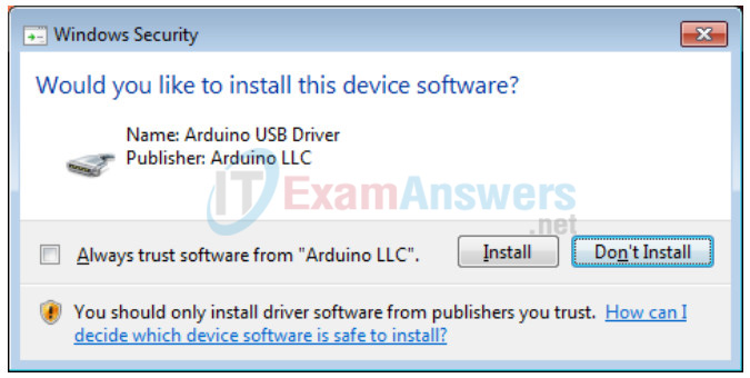
b. Allow the installation of the Arduino USB driver and software when prompted.

c. Click Close when the installation is complete.
Part 2: Using the Arduino IDE Software
In this part, you will connect the Arduino board to the computer via the USB port. You will use an example program to control an LED on pin 13 of the Arduino board.
Step 1: Connect the Arduino board
a. Connect the USB cable to the Arduino board and to the USB port on the PC and connect the board to an external power source if necessary. A green LED is lit to indicate it is powered up.
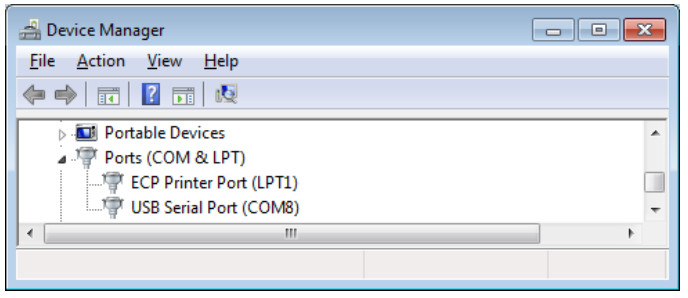
b. Open Device Manager to locate the port used by the Arduino board.
c. Expand Ports (COM & LPT).
d. Note the USB Serial Port location. In this example, it was assigned COM8.

Step 2: Install the LED.
Depending on the model of your Arduino board, you may have a built-in LED attached to digital pin 13. Beside the power indicator LED, another on-board LED is lit if your board has a built-in LED. You can use the built-in LED for the lab. If your board does not have a built-in LED or you choose to use a different LED, you can attach an LED to the board. The steps below are optional if your board has a built-in LED.
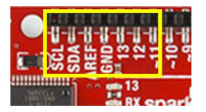
a. Locate pin 13 and ground (GND) on the board. The sample image below is an example from Arduino RedBoard.

b. Connect an LED to pin 13 and ground. LEDs are directional components and the legs on the LEDs have two different lengths. The shorter leg goes into the hole marked GND, and the longer leg goes into the hole marked 13.
Step 3: Run sample code.
a. Launch Arduino.
b. To use one of the sample programs, Blink, click File > Examples > Basics > Blink.
c. Read through the comments at the top of the program. The comment section explains the functions of the program and contains other information about the program.
/*
  Blink
  Turns on an LED on for one second, then off for one second, repeatedly. Most
Arduinos have an on-board LED you can control. On the Uno and
  Leonardo, it is attached to digital pin 13. If you're unsure what
  pin the on-board LED is connected to on your Arduino model, check
  the documentation at http://www.arduino.cc
This example code is in the public domain. modified 8 May 2014
  by Scott Fitzgerald
*/
What is the purpose of this program?
The purpose of this program is to turn an LED on and off for one second at each action repeatedly.
d. To verify the correct board is selected, click Tools > Board. It should be Arduino / Genuino Uno if your board is Arduino Uno or Redboard.
e. To verify the correct port is selected, click Tools > Port. The selected port should be the same port as noted in Device Manager > Ports (COM & LPT).
f. Click Sketch > Verify/Compile to compile the program.
g. Click Sketch > Upload to upload the compiled code to your board.
h. Observe the blinking rate.
i. Scroll down and read through the code. What is the current blinking rate? What can you do to change the blinking rate?
At this time, the LED turns on for 1 second and turns off for 1 second. You can modify the flashing speed by changing the delay.
