11.4.6 Packet Tracer – Implement a Local SPAN Answers version
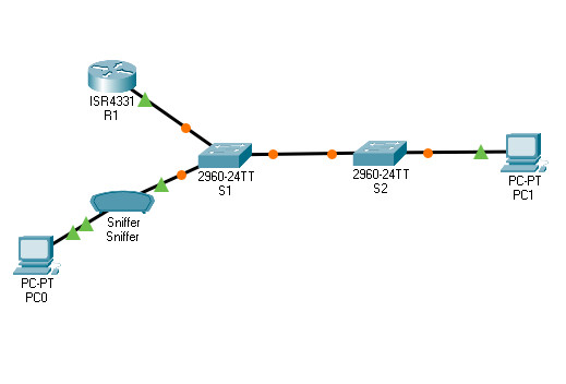
Topology

11.4.6 Packet Tracer – Implement a Local SPAN
Addressing Table
| Device | Interface | IP Address | Subnet Mask | Default Gateway |
|---|---|---|---|---|
| R1 | G0/0/1 | 192.168.1.1 | 255.255.255.0 | N/A |
| S1 | VLAN 1 | 192.168.1.2 | 255.255.255.0 | 192.168.1.1 |
| S2 | VLAN 1 | 192.168.1.3 | 255.255.255.0 | 192.168.1.1 |
| PC0 | NIC | 192.168.1.254 | 255.255.255.0 | 192.168.1.1 |
| PC1 | NIC | 192.168.1.10 | 255.255.255.0 | 192.168.1.1 |
Objectives
- Part 1: Verify Connectivity and Configure the Sniffer
- Part 2: Configure Local SPAN and Capture Copied Traffic
Background / Scenario
As the network administrator you want to analyze traffic entering and exiting the local network. To do this, you will set up port mirroring on the switch port connected to the router and mirror all traffic to another switch port. The goal is to send all mirrored traffic to an intrusion detection system (IDS) for analysis. In this implementation, you will send all mirrored traffic to a sniffer which will display the traffic. To set up port mirroring, you will use the Switched Port Analyzer (SPAN) feature on the Cisco switch. SPAN is a type of port mirroring that sends copies of a frame entering a port, out another port on the same switch.
Instructions
Part 1: Verify Connectivity and Configure the Sniffer
In this part, you will verify end-to-end connectivity and verify the configuration on the sniffer. The privileged EXEC password is class and the vty password is cisco for simplicity.
Step 1: Verify end-to-end connectivity.
From the PCs, you should be able to ping the interface on R1, S1, and S2.
If the pings are not successful, troubleshoot the basic device configurations before continuing.
Step 2: Configure the Sniffer.
a. Access the Sniffer and click GUI.
b. Verify Service is set to On.
c. Click Edit Filters and select ICMP.
d. Leave the Sniffer window open.
Part 2: Configure Local SPAN and Capture Copied Traffic
To configure Local SPAN, you need to configure one or more source ports called monitored ports and a single destination port also called a monitored port for copied or mirrored traffic to be sent out from. SPAN source ports can be configured to monitor traffic in either ingress or egress, or both directions (default).
The SPAN source port will need to be configured on the port that connects to the router on S1 switch port F0/5. This way all traffic entering or exiting the LAN will be monitored. The SPAN destination port will be configured on S1 switch port F0/6 which is connected to a sniffer.
Step 1: Configure SPAN on S1.
a. Access S1 and configure the source and destination monitor ports on S1. Now all traffic entering or leaving F0/5 will be copied and forwarded out of F0/6.
S1(config)# monitor session 1 source interface f0/5
S1(config)# monitor session 1 destination interface f0/6
b. Verify SPAN configuration for session 1.
S1# show monitor session 1
Session 1
---------
Type                : Local Session
Description         : -
Source Ports        :
    Both            : Fa0/5
Destination Ports   : Fa0/6
    Encapsulation   : Native
          Ingress   : Disabled
Step 2: Telnet into R1 and create ICMP traffic on the LAN.
a. Telnet from S1 to R1. The password is cisco.
S1# telnet 192.168.1.1
Trying 192.168.1.1 . . . Open

User Access Verification

Password:
R1>
b. From user privileged mode, ping PC0, PC1, S1 and S2.
R1> enable
Password:
R1# ping 192.168.1.10
Type escape sequence to abort.
Sending 5, 100-byte ICMP Echos to 192.168.1.10, timeout is 2 seconds:
!!!!!
Success rate is 100 percent (5/5), round-trip min/avg/max = 1/1/4 ms
R1# ping 192.168.1.2
<Output omitted>
R1# ping 192.168.1.3
<Output omitted>
Step 3: Examine the ICMP packets.
a. Return to Sniffer.
b. Examine the captured ICMP packets. Click each ICMP and scroll down to the ICMP heading. Note the source and destination IP addresses.
Questions:
Were the pings from R1 to PCs and switches successfully copied and forwarded out F0/6 to Sniffer?
Yes
Was the traffic monitored and copied in both directions?
Yes
Answer Scripts
Switch S1
enable

config terminal

monitor session 1 source interface f0/5

monitor session 1 destination interface f0/6

end
