2.2.1.4 Lab – Create an IoT Sensor-Actuator System (Instructor Version)
Instructor Note: Red font color and completed code cells indicate that the information appears in the instructor copy only.
Topology
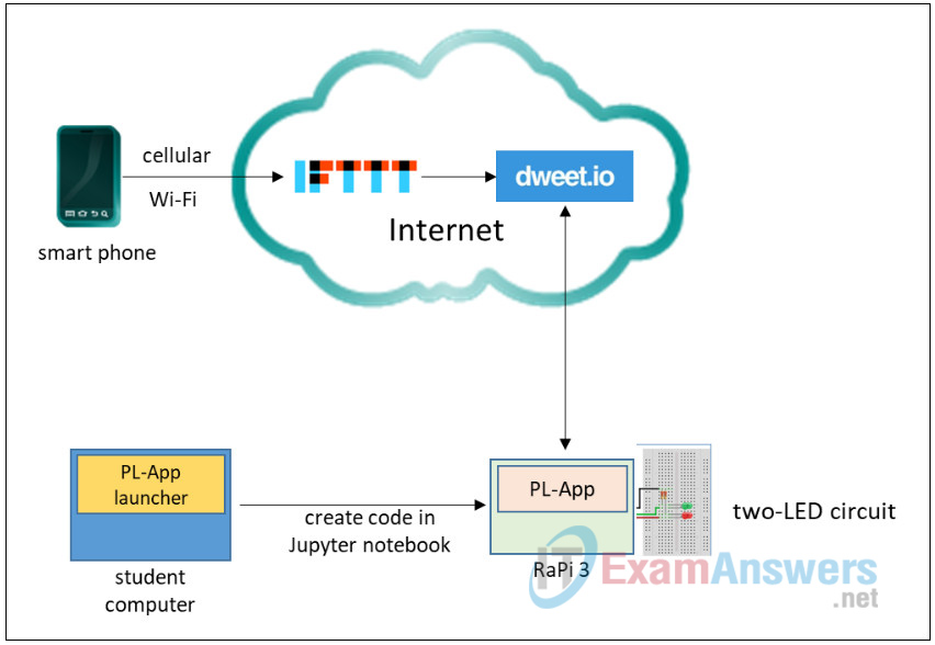
Connectivity requirements: As shown in the topology, the Raspberry Pi must be able to reach the Internet and must also be reachable from a student computer via the network so that code can be completed in a Jupyter Notebook.
Addressing
No specific addressing is required as long as the communications requirements are met.
Objectives
- Build a simple electronic circuit that is under control of the Raspberry Pi.
- Create a simple control app using IFTTT and dweet.io.
- Configure an IFTTT app as a widget in Android or iOS.
- Complete Python code that will control an end-to-end IoT system.
- Use a smartphone to trigger actions of Raspberry Pi through IFTTT
- Describe possible security vulnerabilities of such an IoT system
Background / Scenario
IoT systems often consist not only of sensor and actuator electronics, but also of software applications that control the systems through a cloud platform. In home automation systems, sensors and actuators in the home connect to the local network over Wi-Fi and a cloud management platform through on the Internet. The cloud management platform collects data from the system and enables control of it from either a browser or specialized app that runs on a mobile device.
When evaluating system security, it is useful to break the system down into parts in order to identify different areas of potential vulnerability.
In this lab, you will build a simple circuit that is controlled by the Raspberry Pi. Then, through the integration of two web services, you will create a simple app that can control the circuit from a mobile device, either over a cellular or Wi-Fi connection. To complete this lab, you will use your circuit building and Python skills from the IoT Connecting Things course. Finally, you will analyze the system to identify potential vulnerabilities at the device, communication, and application layers of the simplified IoT model.
Required Resources
- PC or laptop
- Raspberry Pi 3, Model B or B+, with PL-App
- Breadboard
- Two 330 Ohm resistors
- Two LEDs, one red and one green
- Jumper wires
- IFTTT account
- Smartphone with recent operating system (Requires iOS 9.0 or higher, or Android devices running 4.1 or higher.)
- IFTTT app for Android or iOS
- Incoming Internet access to the Raspberry Pi over HTTPS (port 443)
- Network connectivity between host and Raspberry Pi
Part 1: Build and Test the Circuit
In this part of the lab, you will build the electronic circuit and test the circuit with Python code.
Step 1: Build the circuit and connect to the Raspberry Pi
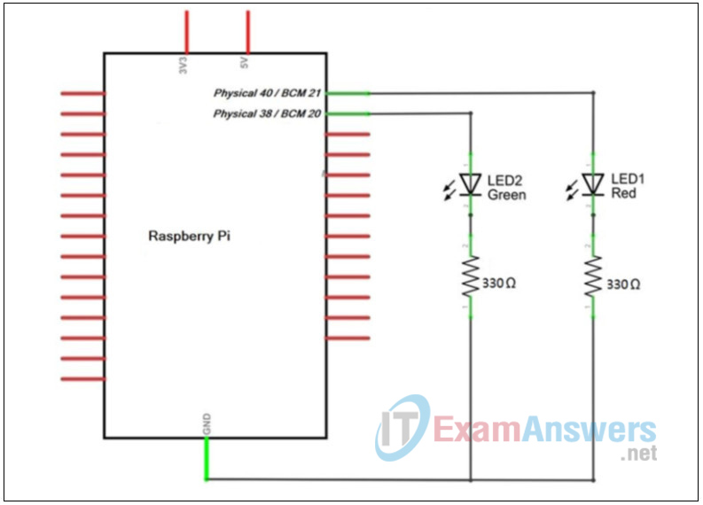
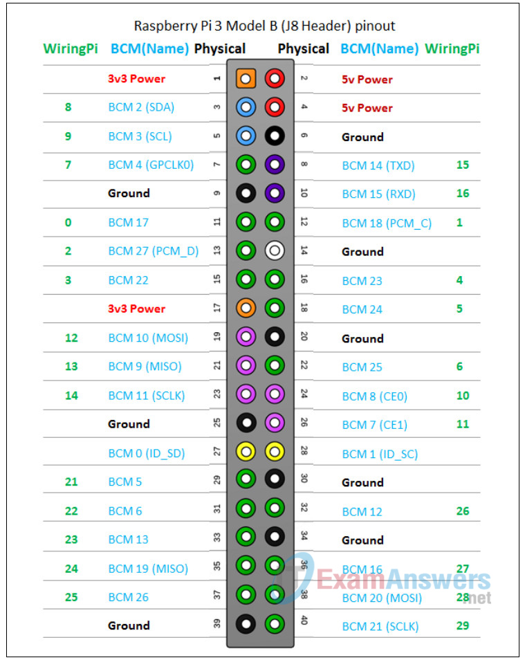
a. Obtain the required components and construct the circuit as shown below. The anode leg of the red LED is to be connected to GPIO pin number 21 based on the BCM GPIO scheme of the Raspberry Pi 3. The anode leg of the green LED is to be connected to the GPIO pin number 20 based on the BCM GPIO scheme of the Raspberry Pi 3.
Use the schematic to make the connection from the circuit to the Raspberry Pi.
Circuit:
Pinouts:
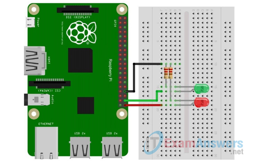
When complete, your circuit should resemble the illustration below:
Step 2: Test the circuit
Complete and run the code in Code Cell 1 according to the instructions in the code comments. Run the code and observe the circuit.
a. Import the modules that are required for the lab.
# Code Cell 1.
# Import the dweepy module that is a collection of functions that make it
# easier to communicate with dweet.io
import dweepy

# Import the GPIO modules to control the GPIO pins of the Raspberry Pi
import RPi.GPIO as GPIO

# Import to clear cell output with code
from IPython.display import clear_output

# Import the time module to control the timing of your application (e.g. add delay, etc.)
import time
b. Setup the Raspberry Pi hardware. Add values for the pin numbers for the GreenLEDPin and RedLEDPin variables. Get the values you need from the circuit connections.
In this code cell, and several others below, students are required to add values to the code. The areas where values are required are indicated by comments that say “Add values.” In addition, the areas of code requiring completion are indicated with lines of equal signs: ===================.
# Code Cell 2.
#Setup hardware
# Set the desired pin numbering scheme:
GPIO.setmode(GPIO.BCM)
GPIO.setwarnings(False)

#Create variables for the GPIO PINs the LEDs are connected to
# ============================================
# the PIN of the green LED
GreenLEDPin = #Add values: add the pin number for the green LED
# the PIN of the red LED
RedLEDPin = #Add values: add the pin number for the red LED
#=============================================

# Setup the direction of the GPIO pins - either INput or OUTput
# The PINs that connect LEDs must be set to OUTput mode:
GPIO.setup(GreenLEDPin, GPIO.OUT)
GPIO.setup(RedLEDPin, GPIO.OUT)
c. Test your circuit. Turn the LEDs on and off by setting their output values to True or False in the code below. Add values for the second pair of on and off settings. Use the first set, and the comments to guide you. Timers are used to make it easier to observe the LEDs. Run the code Cells 1, 2, and 3 and observe the results.
# Code Cell 3.
#Test the circuit by changing the state of the GPIO pins
#This code will cycle twice.
for i in range(2):
    print("Green ON Red Off")
    GPIO.output(GreenLEDPin, True) # True = set 3.3V on the pin
    GPIO.output(RedLEDPin, False)  # False = set 0V on the pin
    time.sleep(1)  #Wait one second.
    print("Green OFF Red ON")
    #======================================
    GPIO.output(GreenLEDPin, False ) # Add values: turn the LED off
    GPIO.output(RedLEDPin, True ) # Add values: turn the LED on
    #======================================
    time.sleep(1)   #Wait one second.
GPIO.output(RedLEDPin, False) #turn off red LED after loop
What happens when the code successfully runs?
The green LED lights for one second. It goes out and the red LED lights. Then it goes out. This happens two times.
d. Modify the code to change its behavior. For example, change the number of times that the code cycles through changing the LED that is lit. Also try changing the time that the LEDs are lit in each cycle.
What did you change in the code to make change the number of times that the LEDs cycle?
In Code cell 3, the value passed to the range() function in the for i in range(2): statement.
What did you change in the code to change the time that the LEDs were lit in each cycle?
In code cell 3, the values in one or both of the time.sleep() methods.
If the circuit were attached to different pins on the Pi, what in the code would need to be changed?
In Code Cell 2, the values assigned to the GreenLEDPin and RedLEDPin variables.
Part 2: Create an IFTTT app.
As you may remember from IoT Fundamentals Connecting Things lab 5.3.4.4, IFTTT (If This Then That) is a simple web service that allows the connection of an event to an action. For example, an event, such as a sensor in the home reaching a threshold value, could be configured to trigger a phone call or text to a provided smart phone number. This very simple logic can create very rich functionality.
In this lab, we will use an IFTTT widget to detect a button press on a smart phone or tablet. IFTTT will then trigger a post to a website called dweet.io that serves as a very simple “message broker.”
dweet.io allows a user or application to post a message to a website that can then be retrieved by another application. This is done by creating a “thing.” A thing is a virtual object that holds messages. By referring to the name of the thing in a URL, you can send a message. Similarly, a request can be made to the thing that allows retrieval of the message by any device that knows the name of the thing. This is useful because these messages allow different applications to communicate with one another by using the thing as an intermediary.
In a later part of the lab, the Raspberry Pi will detect whether a message has been posted to the thing by a tap on the IFTTT button widget that has been installed on a smart phone. If a new button tap is detected, the Pi will actuate the circuit by changing the LED that is lit from green to red or vice versa.
Step 1: Register a free user account at IFTTT
a. Go to the IFTTT website.
b. If you do not have an IFTTT user account, click Sign up to register for free. A valid email address is required to register a free user account.
Step 2: Create the IFTTT App
a. After signing up and authenticating with your account, Click My Applets.
b. Click the Services tab and then click New Applet.
c. Click the blue +this text to select the service that will trigger an action, as shown in the figure.

d. In the Search services field, enter button and then click the Button widget tile that appears.
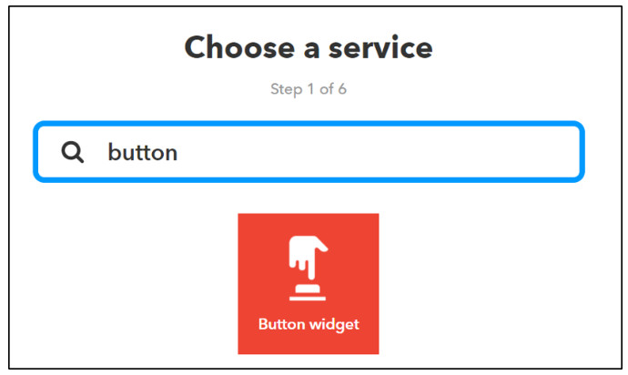
e. Click Connect. On the Choose a Service page, click the Button widget tile.
f. Click the blue +that text to select the action that will be triggered by the button widget.

g. Type webhooks into the search services field and click the Webhooks tile to select this service as the action that will be triggered.
h. We now need to enter in the URL of the dweet thing that will receive a message sent by the Button Widget. First, we need to create a name for our thing. The name should be unique in order to make sure that only messages posted by you will received by the thing. The name of the thing can contain no spaces, but can be hyphenated. Keep the name of your thing private. There is no account-based security on dweet.io. We didn’t even need to register!
Click in the URL field of the Make a web request interface. Enter the following URL by substituting the name your thing where indicated. Do not include the {} characters in the URL.
https://dweet.io/dweet/for/{my-thing-name}?text=mydweet
Students will benefit from exploring the dweet.io functionality and API. There is interactive documentation that allows students to explore various dweet.io functionalities and API concepts. For the sake of brevity, this material is not covered in this lab.
i. Click Create action to create and Finish to save your app. Your completed Applet should look this:
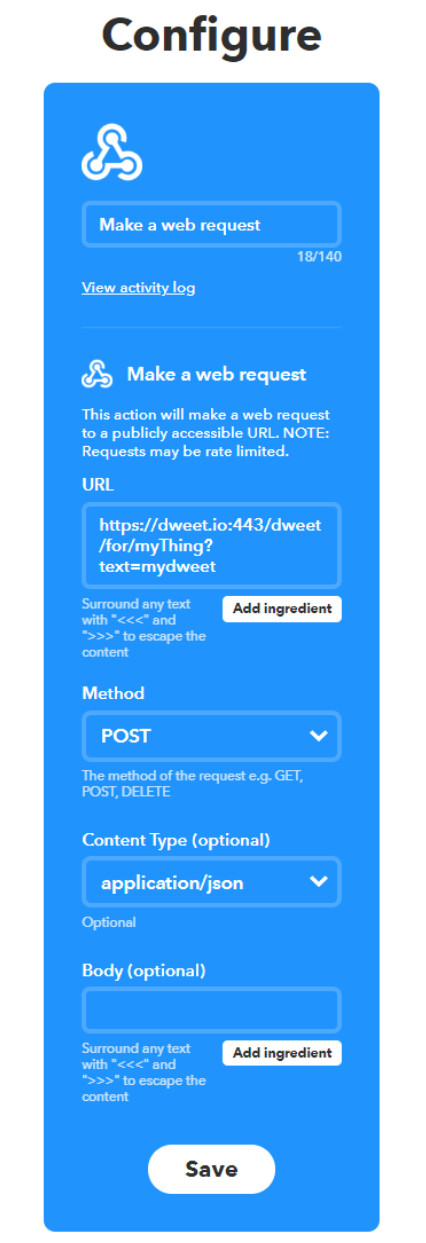
That is it! This is all that you need to do to create the IFTTT app. The other fields on this screen can be left unchanged.
Part 3: Download and configure the IFTTT app on a smart phone
Now that the IFTTT applet has been created, create a widget on a smart phone that will control the LED circuit. The widget will consist of a single button that looks like an icon for a smart phone application. To do this, install the IFTTT app on the smart phone and then use it to install the applet as a widget.
a. From the Apple Store or Google Play Store, search for, download, and install the IFTTT app onto the smart phone. The IFTTT app requires iOS 9.0 or higher, and Android devices running version 4.1 or higher.
b. Install the IFTTT app.
c. In the app, locate the sign in link and sign in with your username and password. You may be prompted to allow the app to user your locator service. This is not necessary.
d. Tap the My Applets icon at the bottom right of the IFTTT app screen. You will see your applet there.
e. Tap the gear icon in the upper right-hand corner of the applet screen and select Widgets.
f. Find your button widget and verify that it is turned on.
g. To add the button widget to your home screen follow the directions that are appropriate for your device.
For Android 4.1 and higher revisions:
1) Go to the device home screen.
2) Press an empty place on the home screen until the home screen configuration menu appears below the views of the available home screens. Select Widgets from the menu.
3) Scroll through the available widgets until you find the IFTTT widgets.
4) Tap and hold the IFTTT Small option. You will return to the home screen views. Move to the home screen that you want to add the widget to and tap the location at which you want to place the widget icon.
5) You will be returned to the IFTTT app. Tap the widget that you want to add to the selected location.
6) You should now be returned to the home screen and your widget will appear there.
For Apple iOS versions 9.0 and higher.
1) Swipe right over the Home screen to bring up the notification screen.
2) Scroll to the bottom of the screen and tap Edit.
3) To add a widget for IFTTT, tap the “+” symbol next to IFTTT.
4) To finish, tap Done.
Part 4: Program the Raspberry Pi to Work with the App
Complete the code that will allow your Raspberry Pi to detect button pushes that have been sent from the phone using the IFTTT webhook applet. To do this, you will first initialize an LED on the Raspberry Pi. The Raspberry Pi will then start to continuously poll the dweet.io thing that was created. The code will compare the timestamp of the last dweet message received by the thing to the timestamp of the most recent dweet message. If the timestamps differ, a new button push has been detected. The LED that is lit will turn off and the other LED will turn on.
Step 1: Prompt the User to Choose an LED to Light
Run the code cells. It is not necessary to run the code that tests your circuit again unless you need to verify that the circuit still works and can be controlled from the Pi.
#Code Cell 4.
while True:
    # Asks the user to select the LED. Put the response into a variable.
    lit = input("Which LED should be lit? (r)ed or (g)reen? (q) to quit: ")
    # convert the input to lowercase and put it in another variable.
    lit1 = lit.lower()
    #Set the LED state based on the user input
    if lit1 == "r": #If the user chose the red LED
        GPIO.output(GreenLEDPin, False) # False = set 0V on the pin
        GPIO.output(RedLEDPin,   True)  # True = set 3.3V on the pin
        break
    elif  lit1 == "g": #If the user chose the green LED
        GPIO.output(GreenLEDPin, True) # True = set 3.3V on the pin
        GPIO.output(RedLEDPin,   False) #False = set 0V on the pin
        break
    elif  lit1 == "q": #If the user chose to quit the program
        break
    else:  #If the user entered something other than r, g, or q.
        print("Please enter r for red, g for green, or q to quit.")
Step 2: Post to your dweet thing at dweet.io.
In this code cell, we will use a special module called dweepy to send messages to a thing at the dweet.io website.
Create a string variable to hold the name of your dweet thing. The name must match the name you use in your IFTTT widget exactly. Set the value of the myThing variable to your dweet thing name.
#Code cell 5

#===================
myThing = "your_thing_name" #Add value: add your dweet thing name
#===================

old_dweet = dweepy.dweet_for(myThing,{"dweet": "1"}) #this function sends data to dweet.io

old_created = old_dweet['created'] #get the time stamp of the first dweet

print(old_created)
Step 3: Monitor dweet.io to detect a new button push
Now, the system needs to monitor the status of the thing on dweet to determine if it has received a button push from the IFTTT button widget. dweet things have several different default properties that you can read from the dweet.io AOI. One of these is the timestamp of the last time the thing was posted to.
We set a variable that holds the timestamp. The code uses a while loop to get the timestamp from the dweet thing every second. It compares the value of the previous dweet timestamp, which is held in the old_created variable, to the value of the timestamp for the latest post to the thing. If the timestamps do not match, it is assumed that a button was pushed on the smart phone.
If a new button push is detected, the currently lit LED is turned off, and the other LED is turned on.
This code uses an endless loop. To stop execution, press the execution button. Some error text may appear as output below the code cell. This is normal.
#Code cell 6.
counter = 0
while True:
    new_dweet = dweepy.get_latest_dweet_for(myThing) #get latest dweet
    new_created = new_dweet[0]["created"] #put the created value of the lastest dweet into a variable
    if new_created != old_created: #check to see if the the old dweet is different from the new dweet
        counter += 1
        print(str(counter) + " New dweet detected!",end='\n')
        old_created = new_created
        if lit1 == "g":
            print("Activate red LED")
            GPIO.output(GreenLEDPin, False) # False = set 0V on the pin
            GPIO.output(RedLEDPin,   True)  # True = set 3.3V on the pin
            lit1 = "r"
        elif lit1 == "r":
            print("Activiate green LED")
            GPIO.output(GreenLEDPin, True)
            GPIO.output(RedLEDPin,   False)
            lit1 = "g"
    time.sleep(1)
Part 5: Use the IFTTT app on the smartphone to trigger an event on the Raspberry Pi
Make sure the smart phone has smart phone Internet connectivity either by Wi-Fi or cellular data. The connection can be either Wi-Fi or cellular data. Using cellular data will prove that the circuit can be controlled from anywhere that has cellular data coverage.
a. Run the code cells. It is not necessary to run Code Cell 3 unless you need to verify that the circuit still works and can be controlled from the Pi.
b. When prompted, initialize an LED when the code cell is run by selecting the color that should be lit.
c. After running the last code cell, the Raspberry Pi will be continuously monitoring the dweet.io thing in order to detect a new button push. On your smart phone, tap the IFTTT button widget. After a brief delay, the LED that is illuminated will change. Try this several times and observe the circuit.
Congratulations! You have created your own end-to-end IoT system.
Reflection
1) This system is not terribly exciting, but can serve as a model for much more interesting IoT systems. Choose an IoT sector and imagine a device that could be actuated by a system like this (instead of, or in addition to, the LEDs). What are the security implications if a hacker was able to take control of the system?
Answers will vary. This system could serve as a metaphor, most obviously, of a home automation application that interacts with a home IoT device such as a light switch or other device that can be turned on or off. With a little additional imagination, the system could be seen as a wirelessly controlled medical device, power grid switchgear, or even the flood gates on a dam.
2) Create a diagram of the system or use the one above. Label each element of the diagram with the layer of the simplified IoT model that it belongs to.
3) What elements of this system make up its attack surface? List all the elements which are potentially vulnerable to a cyberattack. What kinds of attacks are possible? Answer in the table below or create your own table. Think of system in terms of the roles of elements. Rather than “Raspberry Pi” for example, think of “Controller (Raspberry Pi)”
| Layer | Attack Surface | Vulnerability |
|---|---|---|
| Device | Raspberry Pi (controller) | physical tampering, removal of SD card, disconnecting from network. |
| smart phone | loss, unauthorized access to password protected apps | |
| Communication | cellular data connection | possible interception or disruption of signal |
| local network connection | sniffing, password interception, unauthorized device takes control of system, traffic to dweet is not encrypted | |
| Application | web application | credential theft, manipulation of data |
| smart phone app | unauthorized use of app |
