3.2.1.5 Lab – Compromise IoT Device Hardware (Instructor Version)
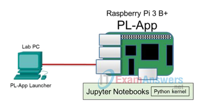
Topology

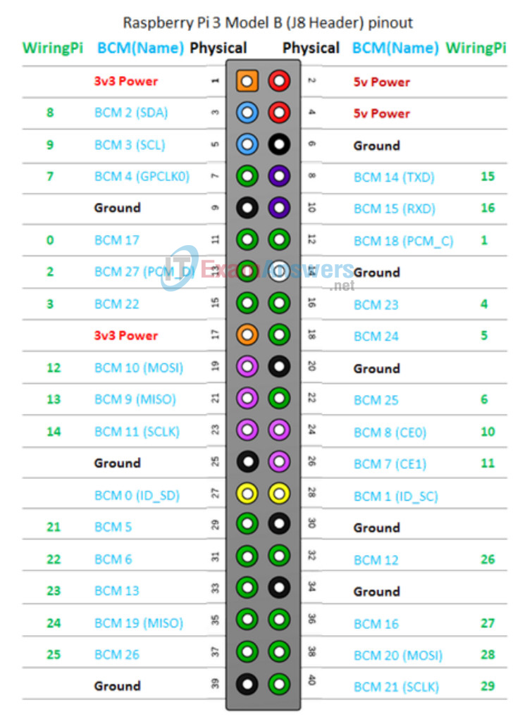
Raspberry Pi Pinout Diagram

Objectives
Perform threat modeling activities to evaluate IoT device hardware and firmware.
- Part 1: Accessing the Raspberry Pi with Serial Interface
- Part 2: Disabling Serial Login Access to Raspberry Pi
Background / Scenario
This lab will demonstrate how an IoT device may be compromised by physically connecting to the device using communication protocols other than Ethernet. A Raspberry Pi could be used for controlling and monitoring many types of equipment. It is important that security is in place at the forefront when configuring and positioning these types of devices. The last part of the lab demonstrates how to secure against these compromises.
The lab makes use of a variant of the RS-232 serial communication standard that has been used since the 1960’s to communicate between various types of equipment.
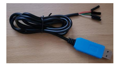
Please note the use of a special cable being used to connect the Raspberry Pi to the PC serial port. Even though some PCs still have conventional RS-232 COM ports it is imperative that direct connections from those pins are not made directly to the Raspberry Pi. The Raspberry Pi uses +3.3v for the serial pins whereas the RS-232 specification indicates voltages up to +13v.
There are other possible methods for reducing the voltage given the header connections on the Raspberry Pi and many other IoT type devices this provides the simplest way to accomplish serial connectivity.
Required Resources
- Raspberry Pi 3 Model B or later (with PL-App)
- 8GB Micro SD card (minimum required)
- PC with IoTSec Kali VM and terminal emulation software, such as PuTTY
- Network connectivity between PC and Raspberry Pi
- adafruit – USB TO TTL SERIAL CABLE – DEBUG / CONSOLE CABLE FOR RASPBERRY PI or compatible cable – adafruit PRODUCT ID: 954 (similar to the one pictured below)

Note: When purchasing a compatible cable look for those using either the Prolific or SiLabs Chipset. Make certain to read the reviews when purchasing a compatible cable to verify compatibility with the Raspberry Pi. It is important that the output voltage be +3.3v.
Part 1: Accessing the Raspberry Pi with the Serial Interface
This part of the lab will create a TTY connection to the Raspberry Pi using a USB to Serial Cable connected to the serial pins on the Raspberry Pi header.
Step 1: Set up the topology.
a. Start the IoT Security lab topology with Kali VM and Raspberry Pi connected physically via an Ethernet cable.
b. Log into Kali VM to start the DHCP server.
root@kali:~# ./lab_support_files/scripts/start_dhcp.sh
[ ok ] Starting isc-dhcp-server (via systemctl): isc-dhcp-server.service.
c. Open a web browser in the Kali VM or your host PC and navigate to the IP address for your Raspberry Pi.
d. Using the pinout diagram above or refer to the diagram at https://pinout.xyz, locate the Raspberry Pi pins listed in the following table.
| USB to Serial Wire | Raspberry Pi Pin |
|---|---|
| Black | 6 – Ground |
| White | 8 – Transmit |
| Green | 10 – Receive |
| Red | Unused |
e. After locating the necessary pins, power off the Raspberry Pi until instructed to power it up again.
(pl-app) root@myPi:/home/pi/notebooks# shutdown -h now
f. Unplug the Raspberry Pi from the power source. With the Raspberry Pi turned off, connect the USB to Serial Cable to the pins listed in the above table on Raspberry Pi.
Step 2: Configure software – Windows (skip this step if using Linux)
a. Install the driver for the adafruit USB to TTL Serial Cable as documented at
https://www.adafruit.com/product/954 for the cable from adafruit and follow the directions provided by the vendor.
b. When complete, plug in the USB to TTL Serial Cable to a USB port on the PC.
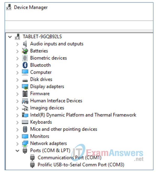
c. Navigate to the Device Manager to determine the COM port assigned to the USB to Serial connection. In this example, Prolific USB-to-Serial is using COM3.

d. The following settings will need to be defined for connecting to the Raspberry Pi using the console port.
| Description | Settings |
|---|---|
| Port | COM port used as indicated in Device Manager |
| Baud Rate | 115200 |
| Data bits | 8 |
| Stop bits | 1 |
| Parity | None |
| Flow control | None |
For example, in PuTTY session screen, select the Serial radio button, input the COM port listed in the Serial line box matches the COM port determined in Device Manager and the correct Baud rate is specified.

Expand Connection and click Serial to verify all the options are configured according to the above table. Click Open to start the terminal session to the Raspberry Pi. PuTTY is waiting for output from the Raspberry Pi or input from the keyboard.

e. Power up the Raspberry Pi. Output from the Raspberry Pi should start scrolling across the screen as shown below.
[      0.000000] Booting Linux on physical CPU 0x0
[      0.000000] Linux version 4.14.30+ (dc4@dc4-XPS13-9333) (gcc version 4.9.3
(crosstool-NG crosstool-ng-1.22.0-88-g8460611)) #1102 Mon Mar 26 16:20:05 BST 2018
[      0.000000] CPU: ARMv6-compatible processor [410fb767] revision 7 (ARMv7),
cr=00c5387d

<Some output omitted>
Welcome to the Chestnut Platform!
 Version: 2.1
  IP: 203.0.113.11
 myPi login:
What version and type of operating system is displayed in the output?
____________________________________________________________
Linux version 4.14.30+
What type of processor is being used?
____________________________________________________________
CPU: ARMv7 Processor +
f. Log in using the credential for the user pi configured for your Raspberry Pi in a previous lab.
Step 3: Configure software – Linux (skip this step if using Windows)
a. On a Linux platform (your host PC) determine the port to use by listing the tty ports in the /dev folder.
user@computer ~ $ ls /dev/ttyUSB*
b. Assuming the USB tty port is USB0, access the USB to Serial connection by typing the following:
user@computer ~ $ screen /dev/ttyUSB0 115200
c. Power up the Raspberry Pi. Output from the Raspberry Pi should start scrolling across the screen as shown below.
[      0.000000] Booting Linux on physical CPU 0x0
[      0.000000] Linux version 4.14.30+ (dc4@dc4-XPS13-9333) (gcc version 4.9.3
(crosstool-NG crosstool-ng-1.22.0-88-g8460611)) #1102 Mon Mar 26 16:20:05 BST 2018
[      0.000000] CPU: ARMv6-compatible processor [410fb767] revision 7 (ARMv7),
cr=00c5387d

<Some output omitted>
Welcome to the Chestnut Platform!
 Version: 2.1

  IP: 203.0.113.11

 myPi login:
What version and type of operating system is displayed in the output?
___________________________________________________________
Linux version 3.18.11-v7+
What type of processor is being used?
___________________________________________________________
CPU: ARMv7 Processor +
d. Login to the Raspberry Pi using the user pi and password configured for your Raspberry Pi.
Part 2: Disabling Serial Login Access to Raspberry Pi
If the Raspberry Pi is intended to be collecting sensitive information, and there is any possibility of physical access to the device, it is probably best to disable login access through the serial line.
Step 1: Connect to the Raspberry Pi through the console
It will be necessary to get a console connection to the Pi either through a direct cable connection or through the PL-App console. Login using the credentials for the user pi as defined for your particular device.
a. After the connection is established, modify the Raspberry Pi configuration using the following command:
pi@myPi$ sudo raspi-config
b. Depending on your Raspberry Pi version, select Interfacing Options -> Serial and press Enter or select Advanced Options -> Serial and press Enter.
c. Select <No> for the question “Would you like a login shell to be accessible over serial?” and press Enter.
d. Select <Yes> for the question “Would you like the serial port hardware to be enable?” and press Enter.
e. On the next screen, verify that the login shell is disabled and serial interface is enabled. Press <OK> to continue.
f. Select <Finish> to exit the configuration window.
g. Reboot the Raspberry Pi when prompted. If not, enter the command sudo reboot at the prompt to reboot the Raspberry Pi. Then watch the output in the terminal application window.
$ sudo reboot
Step 2: Attempt to reconnect with the serial connection
a. After the rebooting process is finished, the Raspberry Pi should no longer display a command prompt in the terminal application. This port may now be used to communicate with other devices for data collection. If there are any connections to the serial port, it is important that they be protected because anyone with the appropriate cable could connect to the device and exfiltrate data.
b. In the Kali VM or the host PC, navigate to the web page of the terminal window of the PL-App for your Raspberry Pi.
c. To simulate data being transmitted from the IoT device, create a Python script by pasting the following at the prompt at the terminal of the PL-App.
Enter the command cat > comout.py at the prompt.
(pl-app) root@myPi:/home/pi/notebooks# cat > comout.py
At the cursor, paste the following script:
#!/usr/bin/env python

import time
import serial

ser = serial.Serial(

       port='/dev/serial0',
       baudrate = 115200,
       parity=serial.PARITY_NONE,
       stopbits=serial.STOPBITS_ONE,
       bytesize=serial.EIGHTBITS,
       timeout=1
)
counter=0

for counter in range(9):
       ser.write(b'Write counter: %d \r\n'%(counter))
       time.sleep(2)
d. After pasting the script into the terminal window, press CTRL-D to close the file.
e. Issue the command python comout.py at the prompt.
(pl-app) root@myPi:/home/pi/notebooks# python comout.py
f. Navigate to the terminal application (PuTTY).
Notice how the output can be read on the terminal. The terminal pauses 2 seconds between each time output is written to the screen as instructed in the Python script.
Reflection
1. Knowing what you know so far, do you think it would be possible to connect two Raspberry Pi devices together using the serial pins? If so, how?
____________________________________________________________
It would be very easy to do. Simply use a jumper wire connecting the Tx pin on Raspberry Pi #1 to the Rx pin on Raspberry Pi #2 and the Rx pin on Raspberry Pi #1 to the Tx pin on Raspberry Pi #2. Because both devices are using +3.3v, there would be no other conversion necessary. Both Raspberry Pi devices could have their serial ports disabled for login and the terminal emulation software set and the same baud rate in order to communicate. It may be necessary to download the ‘screen’ application using ‘apt-get install screen’ on the Raspberry Pi. It would also be possible to leave the serial login enabled on Raspberry Pi #1 and connect to Raspberry Pi #2 using the ‘screen’ application and logging in.
2. What kind of information might you need to know in order to capture the data coming out of the serial port of an IoT device?
____________________________________________________________
In order to capture data, it would be necessary to know the baud rate, stop bits, parity, and flow control settings on the IoT device. The baud rate could be determined through trial and error using the common baud rates. (ie. 2400,4800,9600,19200…..115200)
