CCNA 2 SRWE Final PT Skills Assessment (PTSA)
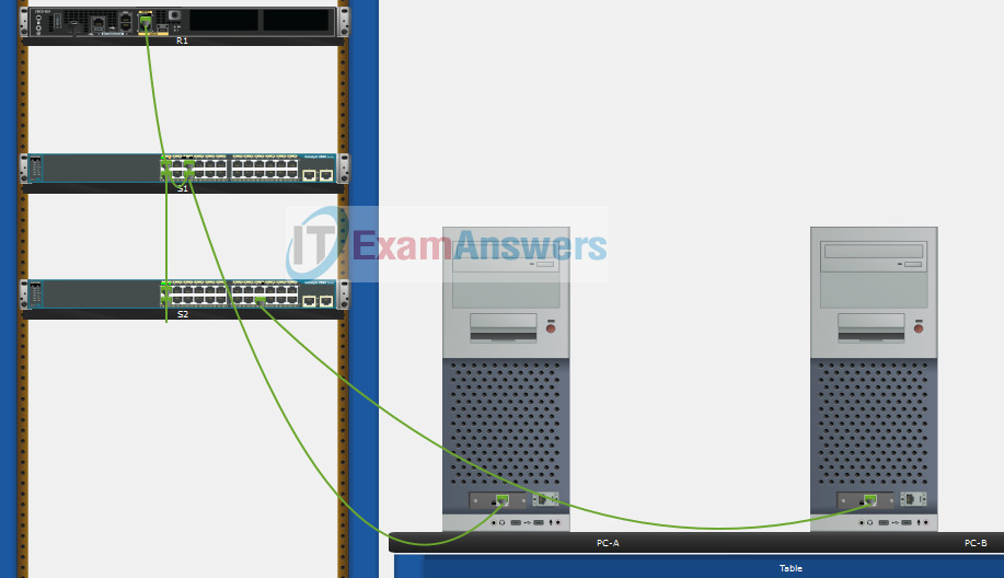
Topology
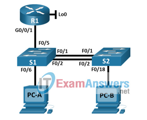
Topology – SRWE Final PT Skills Assessment (PTSA)
VLAN Table
| VLAN | Router Subinterface | VLAN Name |
|---|---|---|
| 2 | G0/0/1.2 | Bikes |
| 3 | G0/0/1.3 | Trikes |
| 4 | G0/0/1.4 | Management |
| 5 | N/A | Parking |
| 6 | G0/0/1.6 | Native |
Addressing Table
| Device / Interface | IP Address/Prefix/Link Local Address | Default Gateway |
|---|---|---|
| R1 G0/0/1.2 | 10.19.8.1 /26 | N/A |
| 2001:db8:acad:a::1 /64 | N/A | |
| fe80::1 | N/A | |
| R1 G0/0/1.3 | 10.19.8.65 /27 | N/A |
| 2001:db8:acad:b::1 /64 | N/A | |
| fe80::1 | N/A | |
| R1 G0/0/1.4 | 10.19.8.97 /29 | N/A |
| 2001:db8:acad:c::1 /64 | N/A | |
| fe80::1 | N/A | |
| R1 G0/0/1.6 | N/A | N/A |
| R1 Loopback0 | 209.165.201.1 /27 | N/A |
| 2001:db8:acad:209::1 /64 | N/A | |
| fe80::1 | N/A | |
| S1 VLAN 4 SVI | 10.19.8.98 /29 | 10.19.8.97 |
| S2 VLAN 4 SVI | 10.19.8.99 /29 | 10.19.8.97 |
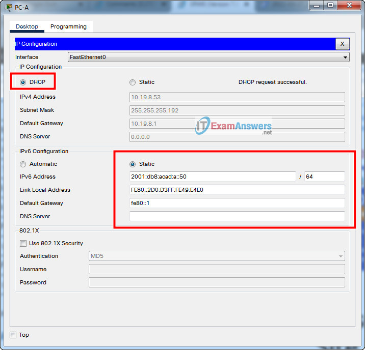
| PC-A NIC | DHCP for IPv4 address | DHCP for IPv4 default gateway |
| 2001:db8:acad:a::50 /64 | fe80::1 | |
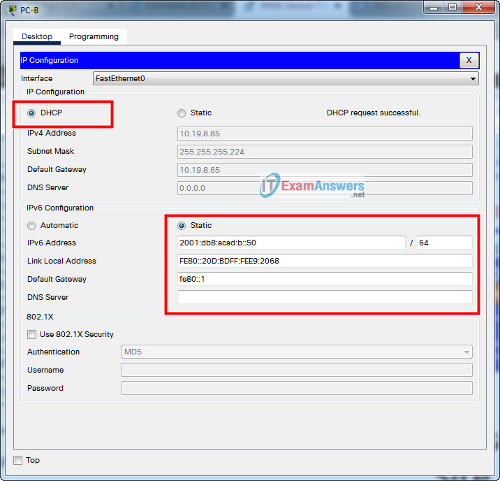
| PC-B NIC | DHCP for IPv4 address | DHCP for IPv4 default gateway |
| 2001:db8:acad:b::50 /64 | fe80::1 |
Note: There is no interface on the router that supports VLAN 5.
SRWE Final PT Skills Assessment (PTSA)
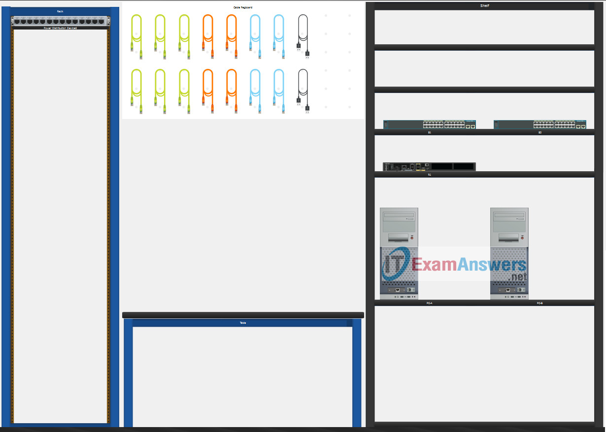
SRWE Final PT Skills Assessment (PTSA)
A few things to keep in mind while completing this activity:
- Do not use the browser Back button or close or reload any exam windows during the exam.
- Do not close Packet Tracer when you are done. It will close automatically.
- Click the Submit Assessment button in the browser window to submit your work.
Assessment Objectives
- Part 1: Build the Network
- Part 2: Configure Initial Device Settings
- Part 3: Configure Network Infrastructure Settings (VLANs, Trunking, EtherChannel)
- Part 4: Configure Host Support
Introduction
In this Packet Tracer Skills Assessment (PTSA) you will configure the devices in a small network. You must configure a router, two switches, and two PCs to support both IPv4 and IPv6 connectivity. Your router and switches must also be managed securely. You will configure inter-VLAN routing, DHCP, Etherchannel, and port-security.
All of your tasks will be performed in PT Physical Mode. You will not be able to access the logical topology for this assessment. Network devices must be configured from a direct console connection.
Instructions
Part 1: Build the Network
- a. Move the required devices into the equipment rack.
- b. Place the PCs on the table.
- c. Connect the devices according to the topology diagram.
Use Copper Straight-Through cable to connect all devices
Turn on the devices PCs and Router
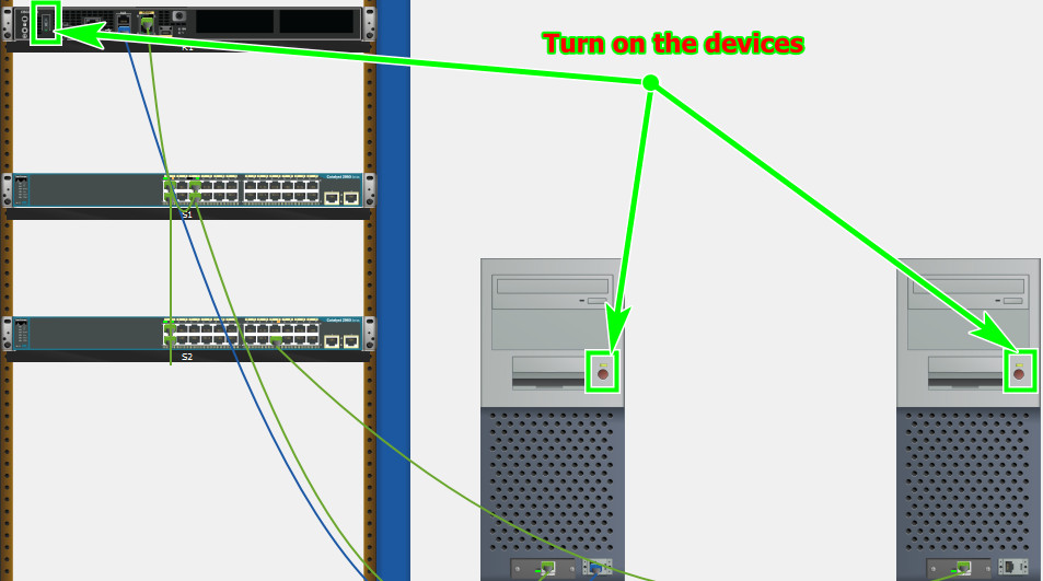
Part 2: Configure Initial Device Settings
All IOS device configuration must be made through a direct console connections.
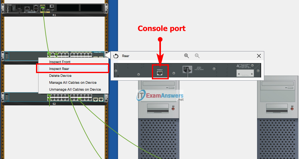
SRWE Final PT Skills Assessment (PTSA)
Step 1: Configure R1 Basic Settings and Device Hardening
a. Configure basic settings.
- Prevent the router from attempting to resolve incorrectly entered commands as domain names.
- Configure the R1 hostname.
- Configure an appropriate MOTD banner.
Router(config)#no ip domain lookup
Router(config)#hostname R1
R1(config)#banner motd #Unauthorized Acess is Prohibited#
b. Configure password security.
- Configure the console password and enable connections.
- Configure an enable secret password.
- Encrypt all clear text passwords.
- Set the minimum length of newly created passwords to 10 characters.
R1(config)#line console 0
R1(config-line)#password ciscoconpass
R1(config-line)#login
R1(config-line)#exit

R1(config)#enable secret ciscoenpass

R1(config)#service password-encryption

R1(config)#security passwords min-length 10
c. Configure SSH.
1) Create an administrative user in the local user database.
- Username: admin
- Encrypted Password: admin1pass
2) Configure the domain name as ccna-ptsa.com
3) Create an RSA crypto key with a modulus of 1024 bits.
4) Ensure that more secure version of SSH will be used.
5) Configure the vty lines to authenticate logins against the local user database.
6) Configure the vty lines to only accept connections over SSH.
R1(config)#username admin secret admin1pass

R1(config)#ip domain name ccna-ptsa.com

R1(config)#crypto key generate rsa
1024

R1(config)#ip ssh version 2

R1(config)#line vty 0 15
R1(config-line)#login local
R1(config-line)#transport input ssh
R1(config-line)#exit
Step 2: Configure router interfaces.
a. Configure R1 with a loopback interface. Configure the loopback0 with IPv4 and IPv6 addressing according to the addressing table.
R1(config)#interface Loopback 0
R1(config-if)#description Loopback
R1(config-if)#ip address 209.165.201.1 255.255.255.224
R1(config-if)#ipv6 address 2001:db8:acad:209::1/64
R1(config-if)#ipv6 address fe80::1 link-local
R1(config-if)#exit
b. Configure Router Subinterfaces
- Prepare the router to be configured with IPv6 addresses on its interfaces.
- Use the information in the Addressing Table and VLAN Table to configure subinterfaces on R1:
- Interfaces should be configured with IPv4 and IPv6 addressing.
- All addressed interfaces should use fe80::1 as the link local address.
- Use the VLAN table to assign VLAN membership to the subinterfaces.
- Be sure to configure the native VLAN interface.
- Configure descriptions for all interfaces.
R1(config)#ipv6 unicast-routing

R1(config)#interface g0/0/1.2
R1(config-subif)#encapsulation dot1Q 2
R1(config-subif)#description Bikes
R1(config-subif)#ip address 10.19.8.1 255.255.255.192
R1(config-subif)#ipv6 address 2001:db8:acad:a::1/64
R1(config-subif)#ipv6 address fe80::1 link-local

R1(config-subif)#interface g0/0/1.3
R1(config-subif)#encapsulation dot1Q 3
R1(config-subif)#description Trikes
R1(config-subif)#ip address 10.19.8.65 255.255.255.224
R1(config-subif)#ipv6 address 2001:db8:acad:b::1/64
R1(config-subif)#ipv6 address fe80::1 link-local

R1(config-subif)#interface g0/0/1.4
R1(config-subif)#encapsulation dot1Q 4
R1(config-subif)#description Management
R1(config-subif)#ip address 10.19.8.97 255.255.255.248
R1(config-subif)#ipv6 address 2001:db8:acad:c::1/64
R1(config-subif)#ipv6 address fe80::1 link-local

R1(config-subif)#interface g0/0/1.6
R1(config-subif)#encapsulation dot1Q 6 native
R1(config-subif)#description Native

R1(config)#interface g0/0/1
R1(config-if)#no shutdown
Step 3: Configure S1 and S2 with Basic Settings and Device Hardening.
Configuration tasks for the switches S1 and S2 include the following:
a. Configure Basic Settings on S1 and S2
- Prevent the switches from attempting to resolve incorrectly entered commands as domain names.int
- Configure the S1 or S2 hostname.
- Configure an appropriate MOTD banner on both switches.
Switch1(config)#no ip domain lookup
Switch1(config)#hostname S1
S1(config)#banner motd #Unauthorized Access is Prohibitted!#
Switch2(config)#no ip domain lookup
Switch2(config)#hostname S2
S2(config)#banner motd #Unauthorized Access is Prohibitted!#
b. Configure Device Hardening on S1 and S2
- 1) Configure the console password and enable connections.
- 2) Configure an enable secret password.
- 3) Encrypt all clear text passwords.
S1(config)#line console 0
S1(config-line)#password ciscoconpass
S1(config-line)#login
S1(config-line)#exit

S1(config)#enable secret ciscoenpass

S1(config)#service password-encryption
S2(config)#line console 0
S2(config-line)#password ciscoconpass
S2(config-line)#login
S2(config-line)#exit

S2(config)#enable secret ciscoenpass

S2(config)#service password-encryption
c. Configure SSH on S1 and S2
- Create an administrative user in the local user database.
- Username: admin
- Password: admin1pass
- Configure the domain name as ccna-ptsa.com
- Create an RSA crypto key with a modulus of 1024 bits.
- Ensure that more secure version of SSH will be used.
- Configure the vty lines to authenticate logins against the local user database.
- Configure the vty lines to accept connections over SSH only.
S1(config)#username admin secret admin1pass

S1(config)#ip domain name ccna-ptsa.com

S1(config)#crypto key generate rsa
1024

S1(config)#ip ssh version 2

S1(config)#line vty 0 15
S1(config-line)#login local
S1(config-line)#transport input ssh
S1(config-line)#exit
S2(config)#username admin secret admin1pass

S2(config)#ip domain name ccna-ptsa.com

S2(config)#crypto key generate rsa
1024

S2(config)#ip ssh version 2

S2(config)#line vty 0 15
S2(config-line)#login local
S2(config-line)#transport input ssh
S2(config-line)#exit
Step 4: Configure SVIs on S1 and S2
Configure the SVI on both switches.
- a. Use the information in the Addressing Table to configure SVIs on S1 and S2 for the Management VLAN.
- b. Configure the switch so that the SVI can be reached from other networks over the Management VLAN.
S1(config)#interface vlan 4
S1(config-if)#ip address 10.19.8.98 255.255.255.248
S1(config-if)#description Management Interface
S1(config-if)#no shutdown
S1(config-if)#exit

S1(config)#ip default-gateway 10.19.8.97
S2(config)#interface vlan 4
S2(config-if)#ip address 10.19.8.99 255.255.255.248
S2(config-if)#description Management Interface
S2(config-if)#no shutdown
S2(config-if)#exit

S2(config)#ip default-gateway 10.19.8.97
Part 3: Configure Network Infrastructure Settings (VLANs, Trunking, EtherChannel)
On S1 and S2, Configure the following.
Step 1: Configure VLANs and Trunking.
- a. Create the VLANs according to the VLAN table.
- b. Create 802.1Q VLAN trunks on ports F0/1 and F0/2. On S1, F0/5 should also be configured as a trunk. Use VLAN 6 as the native VLAN.
S1(config)#vlan 2
S1(config-vlan)#name Bikes
S1(config-vlan)#vlan 3
S1(config-vlan)#name Trikes
S1(config-vlan)#vlan 4
S1(config-vlan)#name Management
S1(config-vlan)#vlan 5
S1(config-vlan)#name Parking
S1(config-vlan)#vlan 6
S1(config-vlan)#name Native

S1(config)#interface range f0/1-2
S1(config-if-range)#switchport mode trunk
S1(config-if-range)#switchport trunk native vlan 6
S1(config-if-range)#switchport trunk allowed vlan 2,3,4,5,6
S1(config-if-range)#exit

S1(config)#interface f0/5
S1(config-if)#switchport mode trunk
S1(config-if)#switchport trunk native vlan 6
S1(config-if)#switchport trunk allowed vlan 2,3,4,5,6
S1(config-if)#exit
S2(config)#vlan 2
S2(config-vlan)#name Bikes
S2(config-vlan)#vlan 3
S2(config-vlan)#name Trikes
S2(config-vlan)#vlan 4
S2(config-vlan)#name Management
S2(config-vlan)#vlan 5
S2(config-vlan)#name Parking
S2(config-vlan)#vlan 6
S2(config-vlan)#name Native

S2(config)#interface range f0/1-2
S2(config-if-range)#switchport mode trunk
S2(config-if-range)#switchport trunk native vlan 6
S2(config-if-range)#switchport trunk allowed vlan 2,3,4,5,6
S2(config-if-range)#exit
Step 2: Configure Etherchannel.
Create Layer 2 EtherChannel port group 1 that uses interfaces F0/1 and F0/2 on S1 and S2. Both ends of the channel should negotiate the LACP link.
S1(config)#interface range f0/1-2
S1(config-if-range)#channel-group 1 mode active
S1(config-if-range)#interface port-channel 1
S1(config-if-range)#exit
S2(config)#interface range f0/1-2
S2(config-if-range)#channel-group 1 mode active
S2(config-if-range)#interface port-channel 1
S2(config-if-range)#exit
Step 3: Configure Switchports.
- a. On S1, configure the port that is connected to the host with static access mode in VLAN 2.
- b. On S2, configure the port that is connected to the host with static access mode in VLAN 3.
- c. Configure port security on the S1 and S2 active access ports to accept only three learned MAC addresses.
- d. Assign all unused switch ports to VLAN 5 on both switches and shut down the ports.
- e. Configure a description on the unused ports that is relevant to their status.
S1(config)#interface f0/6
S1(config-if)#description host
S1(config-if)#switchport mode access
S1(config-if)#switchport access vlan 2
S1(config-if)#switchport port-security
S1(config-if)#switchport port-security maximum 3

S1(config)#interface range f0/3-4, f0/7-24, g0/1-2
S1(config-if-range)#switchport mode access
S1(config-if-range)#switchport access vlan 5
S1(config-if-range)#description Unused Interfaces
S1(config-if-range)#shutdown
S2(config)#interface f0/18
S2(config-if)#switchport mode access
S2(config-if)#switchport port-security
S2(config-if)#switchport access vlan 3
S2(config-if)#switchport port-security maximum 3

S2(config)#interface range f0/3-17, f0/19-24, g0/1-2
S2(config-if-range)#switchport mode access
S2(config-if-range)#switchport access vlan 5
S2(config-if-range)#description Unused Interfaces
S2(config-if-range)#shutdown
Part 4: Configure Host Support
Step 1: Configure Default Routing on R1
- a. Configure an IPv4 default route that uses the Lo0 interface as the exit interface.
- b. Configure an IPv6 default route that uses the Lo0 interface as the exit interface.
R1(config)#ip route 0.0.0.0 0.0.0.0 loopback 0
R1(config)#ipv6 route ::/0 loopback 0
Step 2: Configure IPv4 DHCP for VLAN 2
- a. On R1, create a DHCP pool called CCNA-A that consists of the last 10 host addresses in the VLAN 2 subnet only.
- b. Configure the correct default gateway address in the pool.
- c. Configure the domain name of ccna-a.net.
R1(config)#ip dhcp excluded-address 10.19.8.1 10.19.8.52
R1(config)#ip dhcp pool CCNA-A
R1(dhcp-config)#network 10.19.8.0 255.255.255.192
R1(dhcp-config)#default-router 10.19.8.1
R1(dhcp-config)#domain-name ccna-a.net
R1(dhcp-config)#exit
Step 3: Configure IPv4 DHCP for VLAN 3
- a. On R1, create a DHCP pool called CCNA-B that consists of the last 10 host addresses in the VLAN 3 subnet only.
- b. Configure the correct default gateway address in the pool.
- c. Configure the domain name of ccna-b.net.
R1(config)#ip dhcp excluded-address 10.19.8.65 10.19.8.84
R1(config)#ip dhcp pool CCNA-B
R1(dhcp-config)#network 10.19.8.64 255.255.255.224
R1(dhcp-config)#default-router 10.19.8.65
R1(dhcp-config)#domain-name ccna-b.net
R1(dhcp-config)#exit
Step 4: Configure host computers.
- a. Configure the host computers to use DHCP for IPv4 addressing.
- b. Statically assign the IPv6 GUA and default gateway addresses using the values in the Addressing Table.
Script answers key:
Router R1
enable
configure terminal

no ip domain lookup
hostname R1
banner motd #Unauthorized Acess is Prohibited#

line console 0
password ciscoconpass
login
exit

enable secret ciscoenpass
service password-encryption
security passwords min-length 10

username admin secret admin1pass
ip domain name ccna-ptsa.com
crypto key generate rsa
1024

ip ssh version 2

line vty 0 15
login local
transport input ssh
exit

interface Loopback 0
description Loopback
ip address 209.165.201.1 255.255.255.224
ipv6 address 2001:db8:acad:209::1/64
ipv6 address fe80::1 link-local
exit

ipv6 unicast-routing
interface g0/0/1.2
encapsulation dot1Q 2
description Bikes
ip address 10.19.8.1 255.255.255.192
ipv6 address 2001:db8:acad:a::1/64
ipv6 address fe80::1 link-local

interface g0/0/1.3
encapsulation dot1Q 3
description Trikes
ip address 10.19.8.65 255.255.255.224
ipv6 address 2001:db8:acad:b::1/64
ipv6 address fe80::1 link-local

interface g0/0/1.4
encapsulation dot1Q 4
description Management
ip address 10.19.8.97 255.255.255.248
ipv6 address 2001:db8:acad:c::1/64
ipv6 address fe80::1 link-local

interface g0/0/1.6
encapsulation dot1Q 6 native
description Native

interface g0/0/1
no shutdown
exit

ip route 0.0.0.0 0.0.0.0 loopback 0

ipv6 route ::/0 loopback 0

ip dhcp excluded-address 10.19.8.1 10.19.8.52
ip dhcp pool CCNA-A
network 10.19.8.0 255.255.255.192
default-router 10.19.8.1
domain-name ccna-a.net
exit

ip dhcp excluded-address 10.19.8.65 10.19.8.84
ip dhcp pool CCNA-B
network 10.19.8.64 255.255.255.224
default-router 10.19.8.65
domain-name ccna-b.net
exit
Switch S1
enable
configure terminal

no ip domain lookup
hostname S1
banner motd #Unauthorized Access is Prohibitted!#
line console 0
password ciscoconpass
login
exit
enable secret ciscoenpass
service password-encryption
username admin secret admin1pass
ip domain name ccna-ptsa.com
crypto key generate rsa
1024

ip ssh version 2

line vty 0 15
login local
transport input ssh
exit

interface vlan 4
ip address 10.19.8.98 255.255.255.248
description Management Interface
no shutdown
exit
ip default-gateway 10.19.8.97

vlan 2
name Bikes
vlan 3
name Trikes
vlan 4

name Management
vlan 5
name Parking
vlan 6
name Native

interface range f0/1-2
switchport mode trunk
switchport trunk native vlan 6
switchport trunk allowed vlan 2,3,4,5,6
exit

interface f0/5
switchport mode trunk
switchport trunk native vlan 6
switchport trunk allowed vlan 2,3,4,5,6
exit
interface range f0/1-2
channel-group 1 mode active
interface port-channel 1
exit

interface f0/6
description host
switchport mode access
switchport access vlan 2
switchport port-security
switchport port-security maximum 3

interface range f0/3-4, f0/7-24, g0/1-2
switchport mode access
switchport access vlan 5
description Unused Interfaces
shutdown
Switch S2:
enable
configure terminal
no ip domain lookup
hostname S2
banner motd #Unauthorized Access is Prohibitted!#

line console 0
password ciscoconpass
login
exit

enable secret ciscoenpass
service password-encryption

username admin secret admin1pass
ip domain name ccna-ptsa.com
crypto key generate rsa
1024
ip ssh version 2
line vty 0 15
login local
transport input ssh
exit
interface vlan 4

ip address 10.19.8.99 255.255.255.248
description Management Interface
no shutdown
exit
ip default-gateway 10.19.8.97

vlan 2
name Bikes
vlan 3
name Trikes
vlan 4
name Management
vlan 5
name Parking
vlan 6
name Native

interface range f0/1-2
switchport mode trunk
switchport trunk native vlan 6
switchport trunk allowed vlan 2,3,4,5,6
exit
interface range f0/1-2
channel-group 1 mode active
interface port-channel 1
exit
interface f0/18
switchport mode access
switchport access vlan 3
switchport port-security
switchport port-security maximum 3
interface range f0/3-17, f0/19-24, g0/1-2
switchport mode access
switchport access vlan 5
description Unused Interfaces
shutdown

Stiil valid
Yo. Following the script and descriptions step by step got few “incorrect” stuff made:
Network:S1:User Names:adminIncorrect
Network:S2:User Names:adminIncorrect
Thats completely possible since i have manually made different passwords :D
Whoever:
Configure R1 DHCP Pool A04
Network:R1:DHCP Server:Pools:CCNA-A:Default Gateway – Incorrect
Network:R1:DHCP Server:Pools:CCNA-A:Network Address – Incorrect
Network:R1:DHCP Server:Pools:CCNA-A:Subnet mask – Incorrect
Network:R1:DHCP Server:Pools:CCNA-A:Domain Name – Incorrect
I am unsure why exactly. Probably i did not followed step by step and finished the whole script, then configured the S1/S2. Or maybe i did input wrong something… :)
anyway achieved 88%, 95 out of 107
Still Valid? 08/09/2024
hey I’m kinda stuck at this point
still valid, 06/2024
still valid???
What’s the problem with this? Also the “R1(config)#security passwords min-length 10” part has the same issue.
I am not getting equipment properly. What I need to do
Which version of Packet Tracer are you using?
is it still valid?
Do we need to save copy running-config startup-config for all of the devices?
I have issue. There is 3 console connection needed. Once I connect 1 it stays connected. There is 1 232 connection on ea pc, but theres 3 network devices. when i try and disconnect or delete or remove 1 cable connection to make room for a new connection it doesnt let me. I cant unplug it
Zoom in when you’re trying to unplug the cable, When I go from the router to the Switch I always right click and view the rear of the Switch so when I unplug the console cable from the router, I have a slot to plug it into on the Switch.
4/11/2024 is still valid, guys. all the best
I have issue. There is 3 console connection needed. Once I connect 1 it stays connected. There is 1 232 connection on ea pc, but theres 3 network devices. when i try and disconnect or delete or remove 1 cable connection to make room for a new connection it doesnt let me. I cant unplug it
You need to click and drag the console cable from the point in is inserted back onto the cable pegboard.
Still valid??
why am i getting a Native VLAN Mixmatch ??? please help need to redo exam
Because we have to manually configure native VLAN on both switches by default VLAN
1 is native vlan
I also had an issue with DHCP resolving at the end, using APIPA instead.
In the picture it has you place them in G0/0/1 in the router.
Use the other port in the router to the switch, and give it a minute to resolve.
95%
The problem is pretty simple. The given configuration in R1, did not specify to activate all of the given sub-interface and interface in the router. A simple:
int g0/0/1
no shut
, will fix everything and will allow the dynamic DHCP to activate.
It doesn’t fix the issue, keep using APIPA
valid dec 3 2023
Still valid 25/11/23
Still valid 31/08/23
Thx
still valid for Switching, Routing, and Wireless Essentials ( Version 7.00)
hello, still valid?
yes
i got another exam can u plz update that to newest?
still valid?
This is the best site eveeeeeeeeeeeeeeeer huraaaaaaaaaaah
still valid?
i think no my man i got another exam
This made the life easy.😊😊😊
I agree!
How to download pka file please?
is this the hands on final for the second for CCNA course 2?
Yes. This is for Cisco 2 – Switching and Routing Wireless
how many versions of this packet tracer is there?
On step 2
What is the subif? I think there is something missing.
A little confusion. I fixed it. Thank you!
sub interface
subif means sub interface
How to download pka file please?
Added pka file
I SAVED MY WORK BEFORE COMPLETING HOW COULD I RETRIVE IT COZ ITS REQUESTING FOR INSTRUCTOR TO RENABLE
why do we have to connect S1 and S2 with a straight-through cable? The right one is the cross-over, isn’t it?
R1 Connect Console to PC 1
S1 Connect Console to PC 2
How to setting S2 ? because we cant move the cable console, help me
Still Valid for CCNA 2 SRWE Final PT Skills Assessment (PTSA)or
is this updated?? please be informed.
still valid
still valid??
Yes, this is still valid 100% 107 of 107 points
S1 and S2:
interface range f0/1-2
switchport mode trunk
switchport trunk native vlan 6
switchport trunk allowed vlan 2,3,4,5,6
exit
interface range f0/1-2
channel-group 1 mode active
interface port-channel 1
exit
interface f0/5
switchport mode trunk
switchport trunk native vlan 6
switchport trunk allowed vlan 2,3,4,5,6
exit
Thanksyou!
should be written: ipv6 route ::/1 loopback0
Topology
Can you solve and share plz
can an one help o solve this
thank you for this! 107 points!!
There is a problem in the configuration of the trunk, can not be apply the commands: “switchport trunk allowed vlan” consecutively since any VLAN not specified in this command will not be allowed on this trunk port.
DHCP is not working for IPv4
Used ISR4321 + 2x 2960-24TT
Old news, but on R1 G0/0/1 you need to issue the no shutdown command. That’s ommitted here.
Which mitigation technique would prevent rogue servers from providing false IPv6 configuration parameters to clients?
https://itexamanswers.net/question/which-mitigation-technique-would-prevent-rogue-servers-from-providing-false-ip-configuration-parameters-to-clients
It doesn’t tell or show us how to plug everything up, what am I even supposed to do
If you dont know what to do with this cheat sheet, get out of computer science. You’re embarrassing. You obviously have never even attempted to learn the material if you dont understand basic PHYSICAL configuration. I bet you complain about not getting job opportunities too.
this is somebody’s teacher mad this site exists
you’re washed up man
Right thats definitely a teacher hahaha
im getting DHCP failed with this. any advise?
any luck? getting the same issue ..
same thing, keep getting APIPA on my hosts. any solutions?
Do not apply the commands: “switchport trunk allowed vlan” consecutively since any VLAN not specified in this command will not be allowed on this trunk port.
So, replace
S1(config-if-range)#switchport trunk allowed vlan 2
S1(config-if-range)#switchport trunk allowed vlan 3
S1(config-if-range)#switchport trunk allowed vlan 4
S1(config-if-range)#switchport trunk allowed vlan 5
S1(config-if-range)#switchport trunk allowed vlan 6
by
switchport trunk allowed vlan 2,3,4,5,6
Troubleshoot by checking your network address very well and the range of addresses too
Guys, check your access ports configuration well and also your dhcp pool configuration
Hello, make sure that all cables are connected. Do not forget the cable connection between R1 on g0/0/1 and S1 on F0/5 and also the connection between S1 on F0/2 and S2 on F0/2.
how do you set up the direct console connections
Yeah mate im having the same issue, im unable to enter the configuration interface of all devices
To show Console port on Switch or router , Right click Switch or router –> Inspect Rear –> Console port
you can use console at R1/S1/S2 and plug it into 232 on pc
Select a console cable from the cables. Connect to a pc and connect the other end to the switch or router.
After that, enter into your pc, desktop and select terminal. Click ok and you will get access to either your switch or router
I hope this should be helpful
i already connect PC 1 to R1, and connect PC 2 to S1.. i want to set S2 but i can’t move the console how to move that..
I have same issue. There is 3 console connection needed. Once I connect 1 it stays connected. There is 1 232 connection on ea pc, but theres 3 network devices. when i try and disconnect or delete or remove 1 cable connection to make room for a new connection it doesnt let me. I cant unplug it
my suggestions to add to the above solution:
R1: int g0/0/1.6 –> enc dot1q 6 native
S1: int fa0/6 –> desc host
S1: int fa0/6 –> switchport port-security
S2: int fa0/18 –> switchport port-security
S1+S2: int vlan 4 –> no ipv6
2021 april v7.02:
use (wrong) straight cables for the S1/S2 connections via fa0/1 + fa0/2 to ‘earn’ 100%…
Confirmed and updated, thanks for your sharing!
How do we enter the configuration console.
Also there is no info about how we connect our R1
Choose Console cable, hover to Console port on R1 to connect R1 and PC
I did that and it still tells me Config is locked?
is there any instructions to enter the r1 ?
You must connect R1(console port) and PC1 or PC2(RS 232 port) with console cable. First you need to Power ON R1. Go to PC, open terminal and connect. Same for S1 and S2(Right click on switch > Inspect rear> Zoom it> you find console port). You need 3 console cable for R1,S1,S3 (on the table have 4).Carefully with the delete, because they do not return to the table
The no ipv6 command for S1+S2 int vlan -> no ipv6 can up with errors. Any solution Please
Dear, I don’t understand why we have to use straight through a cable to connect two switches since they ato be communicating via cross-over cable
I agree, it is essentially wrong. But if you want to get 100% completion you will have to, that’s the point…
Thank you for your reply!
I got your points then! Maybe the cisco 2960 switches in this scenario supports the Auto MDI-X. Then the strait through is also working. But I think you are right since if we want to have a perfect score!