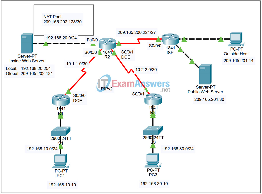
7.2.8 Packet Tracer – Scaling Networks with NAT Answers
Topology

Addressing Table
| Device | Interface | IP Address | Subnet Mask |
|---|---|---|---|
| R1 | Fa0/0 | 192.168.10.1 | 255.255.255.0 |
| S0/0/0 | 10.1.1.1 | 255.255.255.252 | |
| R2 | Fa0/0 | 192.168.20.1 | 255.255.255.0 |
| S0/0/0 | 10.1.1.2 | 255.255.255.252 | |
| S0/0/1 | 10.2.2.1 | 255.255.255.252 | |
| S0/1/0 | 209.165.200.225 | 255.255.255.224 | |
| R3 | Fa0/0 | 192.168.30.1 | 255.255.255.0 |
| S0/0/1 | 10.2.2.2 | 255.255.255.252 | |
| Inside Web Server | NIC | Local: 192.168.20.254 |
255.255.255.252 |
| NIC | Global: 209.165.202.131 |
255.255.255.252 | |
| PC1 | NIC | 192.168.10.10 | 255.255.255.0 |
| PC3 | NIC | 192.168.30.10 | 255.255.255.0 |
| Outside Host | NIC | 209.165.201.14 | 255.255.255.240 |
| Public Web Server | NIC | 209.265.201.30 | 255.255.255.240 |
Learning Objectives
- Configure an ACL to permit NAT.
- Configure static NAT.
- Configure dynamic NAT Overload.
- Configure the ISP router with static route.
- Test connectivity.
Introduction
NAT translates non-routable private, internal addresses into routable, public addresses. NAT has an added benefit of providing a degree of privacy and security to a network because it hides internal IP addresses from outside networks. In this activity, you will configure dynamic and static NAT. The user EXEC password is cisco, and the privileged EXEC password is class.
Task 1: Configure an ACL to Permit NAT
Step 1. Create a named standard ACL.
To define the internal addresses that are translated to public addresses in the NAT process, create a named standard ACL called R2NAT. This list is used in the NAT configuration steps that follow.
R2(config)# ip access-list standard R2NAT
R2(config-std-nacl)# permit 192.168.10.0 0.0.0.255
R2(config-std-nacl)# permit 192.168.20.0 0.0.0.255
R2(config-std-nacl)# permit 192.168.30.0 0.0.0.255
Step 2. Check results.
Your completion percentage should be 11%. If not, click Check Results to see which required components are not yet completed.
Task 2: Configure Static NAT
Step 1. Configure static NAT for an inside web server.
The Inside Web Server needs to have a public IP address that never changes so that it can be accessed from outside the network. Configuring a static NAT address allows the web server to be configured with a private internal address. The NAT process then always maps packets using the public address of the server to the private address.
R2(config)# ip nat inside source static 192.168.20.254 209.165.202.131
Step 2. Check results.
Your completion percentage should be 22%. If not, click Check Results to see which required components are not yet completed.
Task 3: Configure Dynamic NAT Overload
In addition to the public IP address assigned to Inside Web Server, the ISP has assigned three public addresses for your use. These addresses are mapped to all other internal hosts that access the Internet.
To allow more than three internal hosts to access the Internet at the same time, configure NAT with overload to accommodate the additional hosts. NAT overload, also called Port Address Translation (PAT), uses port numbers to distinguish packets from different hosts that are assigned the same public IP address.
Step 1. Define the address pool and configure dynamic NAT.
Enter the following commands to configure the pool of public addresses that are dynamically mapped to the internal hosts.
The first command defines the pool of three public addresses that are mapped to internal addresses.
The second command instructs the NAT process to map the addresses in the pool to the addresses defined in the access list you created in Task 1.
R2(config)# ip nat pool R2POOL 209.165.202.128 209.165.202.130 netmask 255.255.255.252
R2(config)# ip nat inside source list R2NAT pool R2POOL overload
Step 2. Configure the interfaces on R2 to apply NAT.
In interface configuration mode on R2, configure each of the interfaces using the ip nat {inside | outside} command. Because the internal addresses are on networks connected to the Fa0/0, Serial 0/0/0, and Serial0/0/1 interfaces, use the ip nat inside command in configuring these interfaces. The Internet is connected to Serial0/1/0, so use the ip nat outside command on this interface.
Step 3. Check results.
Your completion percentage should be 89%. If not, click Check Results to see which required components are not yet completed.
Task 4: Configure the ISP with a Static Route
Step 1. Configure ISP with a static route to R2.
ISP needs a static route to the public addresses of R2. Use the following command to configure this route.
ISP(config)# ip route 209.165.202.128 255.255.255.224 serial0/0/0
Step 2. Check results.
Your completion percentage should be 100%. If not, click Check Results to see which required components are not yet completed.
Task 5: Test Connectivity
You should now be able to ping from any inside host to Outside Host or Public Web Server.
To see the effects of NAT on a specific packet, enter Simulation mode and observe the packet that originates from PC1.
Click the colored information box associated with that packet as it is passed from R1 to R2. By clicking Inbound PDU Details, you should see that the source address is 192.168.10.10. By clicking Outbound PDU Details, you should see that the source address has been translated to a 209.165.x.x address.
