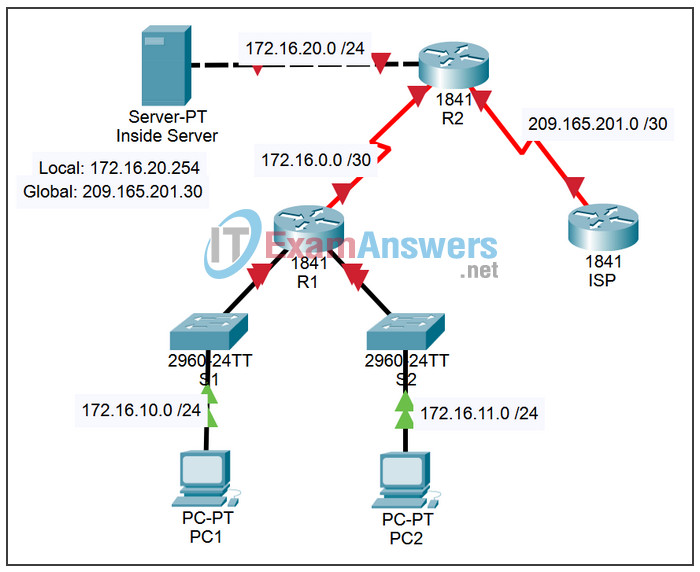
7.4.2 Packet Tracer – Challenge DHCP and NAT Configuration Answers
Topology

Addressing Table
| Device | Interface | IP Address | Subnet Mask |
|---|---|---|---|
| R1 | S0/0/0 | 172.16.0.1 | 255.255.255.252 |
| Fa0/0 | 172.16.10.1 | 255.255.255.0 | |
| Fa0/1 | 172.16.11.1 | 255.255.255.0 | |
| R2 | S0/0/0 | 172.16.0.2 | 255.255.255.252 |
| S0/0/1 | 209.165.201.1 | 255.255.255.252 | |
| Fa0/0 | 172.16.20.1 | 255.255.255.0 | |
| ISP | S0/0/1 | 209.165.201.2 | 255.255.255.252 |
Learning Objectives
- Perform basic router configurations.
- Configure a Cisco IOS DHCP server.
- Configure static and default routing.
- Configure static NAT.
- Configure dynamic NAT with a pool of addresses.
- Configure NAT overload.
Scenario
In this activity, configure the IP address services using the network shown in the topology diagram. If you need assistance, refer back to the basic DHCP and NAT configuration lab. However, try to do as much on your own as possible.
Task 1: Perform Basic Router Configurations
Step 1. Configure the routers.
Configure the R1, R2, and ISP routers according to the following guidelines:
- Configure the device hostname.
- Disable DNS lookup.
- Configure a privileged EXEC mode password.
- Configure a message-of-the-day banner.
- Configure a password for the console connections.
- Configure a password for all vty connections.
- Configure IP addresses on all routers. The PCs receive IP addressing from DHCP later in the lab.
- Enable RIPv2 on R1 and R2. Do not advertise the 209.165.200.224/27 network.
Step 2. Check results.
Your completion percentage should be 57%. If not, click Check Results to see which required components are not yet completed.
Task 2: Configure a Cisco IOS DHCP Server
Configure R1 as the DHCP server for the two directly attached LANs.
Step 1. Exclude statically assigned addresses.
Exclude the first three addresses from each pool.
Step 2. Configure the DHCP pool.
- Create two DHCP pools. Name one of them R1_LAN10 for the 172.16.10.0/24 network, and name the other R1_LAN11 for the 172.16.11.0/24 network.
- Configure each pool with a default gateway and a simulated DNS at 172.16.20.254.
Step 3. Verify the DHCP configuration.
Step 4. Check results.
Your completion percentage should be 73%. If not, click Check Results to see which required components are not yet completed.
Task 3: Configure Static and Default Routing
Step 1. Configure static and default routes.
- Configure ISP with a static route for the 209.165.201.0/27 network. Use the exit interface as an argument.
- Configure a default route on R2 and propagate the route in OSPF. Use the next-hop IP address as an argument.
Step 2. Check results.
Your completion percentage should be 81%. If not, click Check Results to see which required components are not yet completed.
Task 4: Configure Static NAT
Step 1. Statically map a public IP address to a private IP address.
Statically map the inside server IP address to the public address 209.165.201.30.
Step 2. Specify inside and outside NAT interfaces.
Step 3. Verify the static NAT configuration.
Step 4. Check results.
Your completion percentage should be 89%. If not, click Check Results to see which required components are not yet completed.
Task 5: Configure Dynamic NAT with a Pool of Addresses
Step 1. Define a pool of global addresses.
Create a pool named NAT_POOL for the IP addresses 209.165.201.9 through 209.165.201.14 using a /29 subnet mask.
Step 2. Create a standard named access control list to identify which inside addresses are translated.
Use the name NAT_ACL and allow all hosts attached to the two LANs on R1.
Note: The .10 LAN must be configured first, then the .11 LAN. Otherwise, Packet Tracer will not grade the ACL as correct.
Step 3. Establish dynamic source translation.
Bind the NAT pool to the ACL and allow NAT overloading
Step 4. Specify the inside and outside NAT interfaces.
Verify that the inside and outside interfaces are all correctly specified.
Step 5. Verify the dynamic NAT configuration by pinging from PC1 and PC2 to ISP.
Step 6. Check results.
Your completion percentage should be 100%. If not, click Check Results to see which required components are not yet completed.
Task 6: Document the Network
On each router, issue the show run command and capture the configurations.
