
8.5.6 Packet Tracer - Configure Numbered Standard IPv4 ACLs Answers Version
Topology
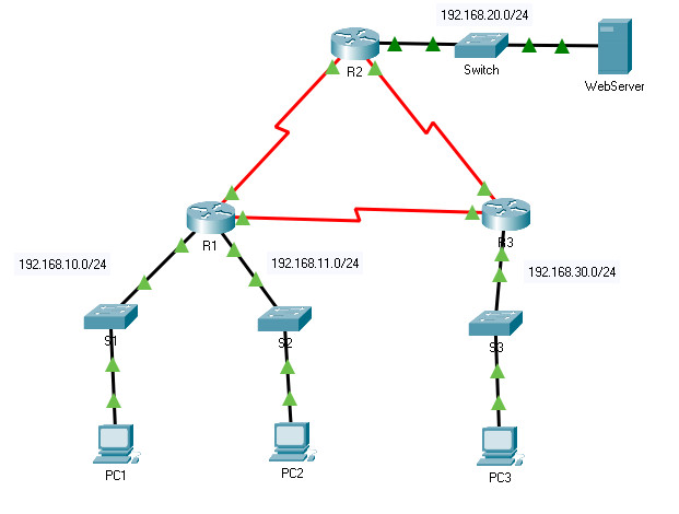
8.5.6 Packet Tracer – Configure Numbered Standard IPv4 ACLs
Addressing Table
| Device | Interface | IP Address | Subnet Mask | Default Gateway |
|---|---|---|---|---|
| R1 | G0/0 | 192.168.10.1 | 255.255.255.0 | N/A |
| G0/1 | 192.168.11.1 | 255.255.255.0 | ||
| S0/0/0 | 10.1.1.1 | 255.255.255.252 | ||
| S0/0/1 | 10.3.3.1 | 255.255.255.252 | ||
| R2 | G0/0 | 192.168.20.1 | 255.255.255.0 | N/A |
| S0/0/0 | 10.1.1.2 | 255.255.255.252 | ||
| S0/0/1 | 10.2.2.1 | 255.255.255.252 | ||
| R3 | G0/0 | 192.168.30.1 | 255.255.255.0 | N/A |
| S0/0/0 | 10.3.3.2 | 255.255.255.252 | ||
| S0/0/1 | 10.2.2.2 | 255.255.255.252 | ||
| PC1 | NIC | 192.168.10.10 | 255.255.255.0 | 192.168.10.1 |
| PC2 | NIC | 192.168.11.10 | 255.255.255.0 | 192.168.11.1 |
| PC3 | NIC | 192.168.30.10 | 255.255.255.0 | 192.168.30.1 |
| WebServer | NIC | 192.168.20.254 | 255.255.255.0 | 192.168.20.1 |
Objectives
- Part 1: Plan an ACL Implementation
- Part 2: Configure, Apply, and Verify a Standard ACL
Background / Scenario
Standard access control lists (ACLs) are router configuration scripts that control whether a router permits or denies packets based on the source address. This activity focuses on defining filtering criteria, configuring standard ACLs, applying ACLs to router interfaces, and verifying and testing the ACL implementation. The routers are already configured, including IP addresses and Enhanced Interior Gateway Routing Protocol (EIGRP) routing.
Instructions
Part 1: Plan an ACL Implementation
Step 1: Investigate the current network configuration.
Before applying any ACLs to a network, it is important to confirm that you have full connectivity. Verify that the network has full connectivity by choosing a PC and pinging other devices on the network. You should be able to successfully ping every device.
Step 2: Evaluate two network policies and plan ACL implementations.
a. The following network policies are implemented on R2:
- The 192.168.11.0/24 network is not allowed access to the WebServer on the 192.168.20.0/24 network.
- All other access is permitted.
To restrict access from the 192.168.11.0/24 network to the WebServer at 192.168.20.254 without interfering with other traffic, an ACL must be created on R2. The access list must be placed on the outbound interface to the WebServer. A second rule must be created on R2 to permit all other traffic.
b. The following network policies are implemented on R3:
- The 192.168.10.0/24 network is not allowed to communicate with the 192.168.30.0/24 network.
- All other access is permitted.
To restrict access from the 192.168.10.0/24 network to the 192.168.30/24 network without interfering with other traffic, an access list will need to be created on R3. The ACL must be placed on the outbound interface to PC3. A second rule must be created on R3 to permit all other traffic.
Part 2: Configure, Apply, and Verify a Standard ACL
Step 1: Configure and apply a numbered standard ACL on R2.
a. Create an ACL using the number 1 on R2 with a statement that denies access to the 192.168.20.0/24 network from the 192.168.11.0/24 network.
R2(config)# access-list 1 deny 192.168.11.0 0.0.0.255
b. By default, an access list denies all traffic that does not match any rules. To permit all other traffic, configure the following statement:
R2(config)# access-list 1 permit any
c. Before applying an access list to an interface to filter traffic, it is a best practice to review the contents of the access list, in order to verify that it will filter traffic as expected.
R2# show access-lists
Standard IP access list 1
       10 deny 192.168.11.0 0.0.0.255
       20 permit any
d. For the ACL to actually filter traffic, it must be applied to some router operation. Apply the ACL by placing it for outbound traffic on the GigabitEthernet 0/0 interface. Note: In an actual operational network, it is not a good practice to apply an untested access list to an active interface.
R2(config)# interface GigabitEthernet0/0
R2(config-if)# ip access-group 1 out
Step 2: Configure and apply a numbered standard ACL on R3.
a. Create an ACL using the number 1 on R3 with a statement that denies access to the 192.168.30.0/24 network from the PC1 (192.168.10.0/24) network.
R3(config)# access-list 1 deny 192.168.10.0 0.0.0.255
b. By default, an ACL denies all traffic that does not match any rules. To permit all other traffic, create a second rule for ACL 1.
R3(config)# access-list 1 permit any
c. Verify that the access list is configured correctly.
R3# show access-lists
Standard IP access list 1
       10 deny 192.168.10.0 0.0.0.255
       20 permit any
d. Apply the ACL by placing it for outbound traffic on the GigabitEthernet 0/0 interface.
R3(config)# interface GigabitEthernet0/0
R3(config-if)# ip access-group 1 out
Step 3: Verify ACL configuration and functionality.
a. Enter the show run or show ip interface gigabitethernet 0/0 command to verify the ACL placements.
b. With the two ACLs in place, network traffic is restricted according to the policies detailed in Part 1. Use the following tests to verify the ACL implementations:
- A ping from 192.168.10.10 to 192.168.11.10 succeeds.
- A ping from 192.168.10.10 to 192.168.20.254 succeeds.
- A ping from 192.168.11.10 to 192.168.20.254 fails.
- A ping from 192.168.10.10 to 192.168.30.10 fails.
- A ping from 192.168.11.10 to 192.168.30.10 succeeds.
- A ping from 192.168.30.10 to 192.168.20.254 succeeds.
c. Issue the show access-lists command again on routers R2 and R3. You should see output that indicates the number of packets that have matched each line of the access list. Note: The number of matches shown for your routers may be different, due to the number of pings that are sent and received.
R2# show access-lists
Standard IP access list 1
       10 deny 192.168.11.0 0.0.0.255 (4 match(es))
       20 permit any (8 match(es))

R3# show access-lists
Standard IP access list 1
       10 deny 192.168.10.0 0.0.0.255 (4 match(es))
       20 permit any (8 match(es))
Download Completed Packet Tracer (.pka) File (100%)
Router R2
! ==============================================================
!--- 8.5.6 Packet Tracer - Configure Numbered Standard IPv4 ACLs
!--- ANSWER SCRIPT FOR ROUTER R2
!--- Usage: from the console (or CLI tab) on R2, enter privileged EXEC mode with "enable",
!--- then paste this whole file. Every line beginning with "!" is a comment; IOS ignores it.
!--- R2 is already fully addressed with EIGRP routing configured - the only task here is
!--- adding standard ACL 1, which blocks the 192.168.11.0/24 network (PC2, on R1's second
!--- LAN) from reaching the Web Server (192.168.20.0/24) attached to R2's own G0/0, while
!--- permitting everyone else.
! ==============================================================

enable
configure terminal

! --------------------------------------------------------------
!--- Part 2, Step 1a-b: Build the ACL BEFORE applying it (best practice per the lab's
!--- own note: "it is not good practice to apply an untested access list to an active
!--- interface"). Standard ACLs only match on source address, so no destination/mask needed.
! --------------------------------------------------------------
access-list 1 deny 192.168.11.0 0.0.0.255
!--- Standard ACLs implicitly deny everything not matched - this line is required so
!--- every other network (PC1, PC3, and R2's own traffic) still gets through.
access-list 1 permit any

! --------------------------------------------------------------
!--- Part 2, Step 1d: Apply the ACL outbound on G0/0 - traffic is filtered as it leaves
!--- toward the Web Server, not as it arrives from the WAN side.
! --------------------------------------------------------------
interface GigabitEthernet0/0
 ip access-group 1 out

end

! --------------------------------------------------------------
!--- Operational habit (not explicitly required by this lab): save to NVRAM.
! --------------------------------------------------------------
copy running-config startup-config

! ==============================================================
!--- Verification (from R2 and the PCs):
!---   R2# show access-lists -> Standard IP access list 1: 10 deny 192.168.11.0 0.0.0.255,
!---   20 permit any (match counts will accumulate as the test pings below are run)
!---   R2# show run | include interface|access -> confirms "ip access-group 1 out" under G0/0
!---   PC1 (192.168.10.10) > ping 192.168.20.254 (Web Server) -> succeeds
!---   PC2 (192.168.11.10) > ping 192.168.20.254 (Web Server) -> fails (blocked by ACL 1)
!---   PC3 (192.168.30.10) > ping 192.168.20.254 (Web Server) -> succeeds
! ==============================================================
Router R3
! ==============================================================
!--- 8.5.6 Packet Tracer - Configure Numbered Standard IPv4 ACLs
!--- ANSWER SCRIPT FOR ROUTER R3
!--- Usage: from the console (or CLI tab) on R3, enter privileged EXEC mode with "enable",
!--- then paste this whole file. Every line beginning with "!" is a comment; IOS ignores it.
!--- R3 is already fully addressed with EIGRP routing configured - the only task here is
!--- adding standard ACL 1, which blocks the 192.168.10.0/24 network (PC1, on R1's first
!--- LAN) from reaching PC3 (192.168.30.0/24) attached to R3's own G0/0, while permitting
!--- everyone else.
! ==============================================================

enable
configure terminal

! --------------------------------------------------------------
!--- Part 2, Step 2a-b: Build the ACL BEFORE applying it (same best-practice order as
!--- R2 - review/verify the list with "show access-lists" before wiring it to an interface).
! --------------------------------------------------------------
access-list 1 deny 192.168.10.0 0.0.0.255
!--- Standard ACLs implicitly deny everything not matched - this line is required so every
!--- other network (PC2 and the Web Server's network) still gets through to PC3.
access-list 1 permit any

! --------------------------------------------------------------
!--- Part 2, Step 2d: Apply the ACL outbound on G0/0 - traffic is filtered as it leaves
!--- toward PC3, not as it arrives from the WAN side.
! --------------------------------------------------------------
interface GigabitEthernet0/0
 ip access-group 1 out

end

! --------------------------------------------------------------
!--- Operational habit (not explicitly required by this lab): save to NVRAM.
! --------------------------------------------------------------
copy running-config startup-config

! ==============================================================
!--- Verification (from R3 and the PCs):
!---   R3# show access-lists -> Standard IP access list 1: 10 deny 192.168.10.0 0.0.0.255,
!---   20 permit any (match counts will accumulate as the test pings below are run)
!---   R3# show run | include interface|access -> confirms "ip access-group 1 out" under G0/0
!---   PC1 (192.168.10.10) > ping 192.168.30.10 (PC3) -> fails (blocked by ACL 1)
!---   PC2 (192.168.11.10) > ping 192.168.30.10 (PC3) -> succeeds
!---
!--- NOTE on the lab's own printed match counts: after running the 6 verification pings,
!--- the lab document shows R3's ACL as "10 deny ... (4 matches) / 20 permit any (8
!--- matches)" - identical to R2's counts. But only two of the six test pings actually
!--- cross R3's G0/0 outbound (PC1->PC3 and PC2->PC3; the PC3->Web Server ping crosses
!--- R2's G0/0, not R3's, and the other three pings never reach R3 at all), which would
!--- give 4 deny / 4 permit here, not 4/8. This looks like R2's numbers were reused by
!--- mistake rather than reflecting R3's actual traffic - though the lab explicitly notes
!--- match counts "may be different" depending on how many pings were sent, so treat the
!--- exact numbers as illustrative rather than a hard target to match.
! ==============================================================


