3.2.6.4 Lab – Interfacing Arduino code and Python code (Instructor Version)
Objectives
- Use the Serial interface of the Arduino board to exchange data between an Arduino and a Raspberry Pi
- Use Python to read data from the Arduino’s USB Serial interface
- Use Python to write data to the Arduino’s USB Serial interface
Background
The microcontroller on an Arduino board provides realtime processing capabilities that are needed for precise automation applications. It can also be used to collect data from various analog sensors.
The Raspberry Pi on the other hand lacks true realtime processing capabilities. In many applications it is only used to collect data and control the true realtime processing on an external microcontroller such as the Arduino.
In this lab, you will learn how to use Python to read data from an Arduino board connected to a Raspberry Pi using the USB connection. You will also learn how to use Python to provide control of the Arduino board by exchanging simple messages through the USB connection.
Required Resources
- PC with Internet Access
- Raspberry Pi with power cable and either a wired Ethernet or Wi_Fi network connection
- RedBoard or compatible
- USB cable supplied with PL-Kit
Task 1: Setting up the Arduino board
Step 1: Using a voltage divider to connect a light sensor (photoresistor) to the Arduino
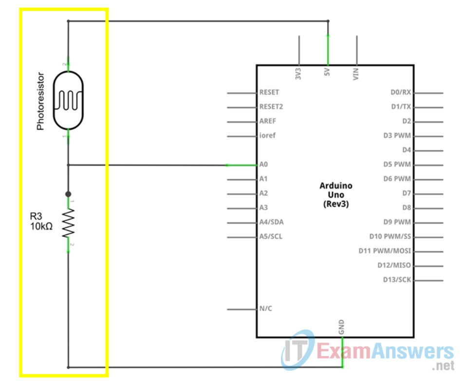
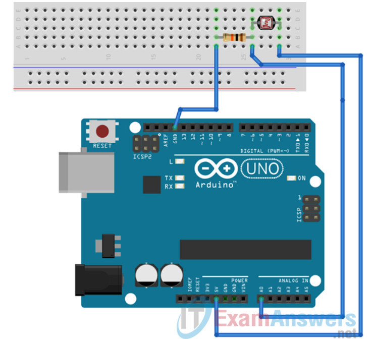
a. Using a breadboard, connect a photoresistor and one 10kOhm resistor. The junction point between the photoresistor and the resistor is connected to the analog A0 input pin of the Arduino board. The ground pin of the board is connected to the other side of the resistor, while the +5V pin of the board is connected to the other side of the photoresistor. The more light comes to the head of the photoresistor, the less the resistivity it has. That means that with more light, the A0 analog input pin will measure higher voltage than in the dark conditions.
Arduino Schematics:
Arduino Physical Layout:
Step 2: Programming Arduino using Arduino IDE
a. For some sensors, and realtime applications, it is necessary to run the processing application code directly on the Arduino microcontroller board. In this lab, the Arduino code is used to read values from analog sensors and send the values over a Serial communication channel to be processed with Python on te Paspberry Pi. The code itself also provides a mechanism to change the default analog pin that is used to read data from. If any data is sent over the Serial interface to the Arduino board, it will try to update the analog input pin number based on the value read from the Serial interface.
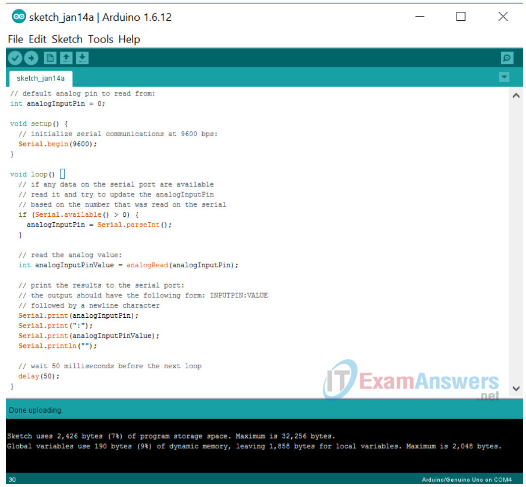
b. Using Arduino IDE runnin on your PC, compile and flash the following code to your Arduino board.
// default analog pin to read from:
int analogInputPin = 0;

void setup() {
  // initialize serial communications at 9600 bps:
  Serial.begin(9600);
}

void loop() {
  // if any data on the serial port are available
  // read it and try to update the analogInputPin
  // based on the number that was read on the serial
  if (Serial.available() > 0) {
    analogInputPin = Serial.parseInt();
  }

  // read the analog value:
  int analogInputPinValue = analogRead(analogInputPin);

  // print the results to the serial port:
  // the output should have the following form: INPUTPIN:VALUE
  // followed by a newline character
  Serial.print(analogInputPin);
  Serial.print(":");
  Serial.print(analogInputPinValue);
  Serial.println("");

  // wait 50 milliseconds before the next loop
  delay(50);
}
c. After the code above has been flashed to the Arduino, the board should continuously send the measured values as a string to the Serial interface.
Task 2:
Step 2: Connect the Arduino to the Raspberry Pi
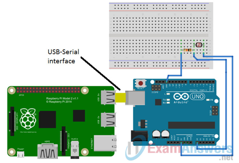
Using a USB cable, connect the Arduino to the Raspberry Pi. Since the Arduino is powered directly from this USB connection, there is no need to provide any additional power to the Arduino. Only provide power to the Raspberry Pi from an external power adapter. The USB cable between the Arduino and the Raspberry Pi is not only used to power the Arduino, but it also provides a serial communication channel to control and monitor the Arduino from applications running on the Raspberry Pi.
Raspberry Pi and Arduino:
Task 3: Python to read and write serial data to the Arduino
Step 1: Setup
a. As seen in the previous task, the analog sensor, in our case a photoresistos, is connected to the Arduino board using the Analog Input pin number 0 (A0). Based on the light conditions above the photoresistor, the A0 pin will measure input Voltage values from 0 to +5V and transform it into digital values from 0 to 1023.
b. Ensure that there is a connection between the Raspberry Pi and the Arduino as specified above. The same USB cable is used to power the Arduino board with the connected sensors, as well as to provide a serial transport channel between the Raspberry Pi and Arduino. The serial transport channel between the Arduino and Raspbery Pi in Linux is usually identified as a device in the /dev directory with a name ttyACM0 or ttyUSB0 (/dev/ttyACM0 or /dev/ttyUSB0).
c. Identify the name of the Arduino’s serial communication device on the PL-App Linux OS, by executing the the code in the following cell. The cell below contains a bash script that idenfifies the device name. Remember the name of the serial communication device – it will be needed for later work.:
Example output:

Once the Arduino’s serial device name has been identified, you can continue by implementing an custom Arduino serial communication.
Step 2: Opening the Serial interface in Python
a. The Python library pyserial is used to read and write data to and from a serial interface. b. To use the pyserial library, import the serial module:
import serial
b. In the next cell, create an object ser that will represent the local serial interface device (/dev/ttyUSB0), specified as the first parameter of the ser = serial.Serial('/dev/ttyUSB0', 9600) command. The second parameter (9600) defines the speed of the serial interface. This number must be the same as specified in the Arduino’s code Serial.begin(9600); in its setup() function.
# make sure to use the correct serial serial communication device name
# e.g. /dev/ttyUSB0, /dev/ttyUSB1, /dev/ttyACM0, ...
#  as you discovered in the steps above
ser = serial.Serial('/dev/ttyUSB0', 9600)
c. If the serial connection has been successfully established, you can use the various functions of the seq object to read and write data to and from the serial interface:
flushInput(): to flush everything that might have been stored in the input buffer before readingreadline(): to read a single line of Bytes data from the serial interfacewrite(): to write Bytes data to the serial interfaceclose(): to close the serial interface (only one application at the time can open the serial interface)
d. Try to execute the code below to read data from the serial interface line by line and print it to the output:
The Arduino’s code is sending data in this form: INPUTPIN:VALUE, where INPUTPIN is the number of the pin where the measurement was taken, and the VALUE is the actual measured value.
# loop until manually stopped
# first flush possibly existing data in the input buffer:
ser.flushInput()
while True:
    try:
        # read a single line from the serial interface represented by the ser object
        lineBytes = ser.readline()
        # convert Bytes returned by the ser.readline() function to String
        line = lineBytes.decode('utf-8')
        # print the read line to the output
        print(line)

    except KeyboardInterrupt:
        break # stop the while loop
e. You can also use the write() function of the ser object to write data to the serial interface. These data can be then processed locally by the Arduino. In this lab, the Arduino accepts as an input serial data that represends the analog input pin to read from. By executing the cell below, you can change the input pin on the Arduino from the default analog input pin 0 to pin 5. If you connect any sensor or just a simple jumper cable to analog pin 5, you can measure the voltage values on analog pin 5.
# write output data to the serial interface
# these data are read by Arduino's serial:
inputPin = 5
#  the write() function expects a bytes parameter
#  therefore the integer inputPin is first turned into a string with the str() function
#  and then the string is turned into Bytes by the encode() function
inputPinStr = str(inputPin)
inputPinStrBytes = inputPinStr.encode()
ser.write(inputPinStrBytes)

# the same code as above, this time it should read data from a new pin
# loop until manually stopped
# first flush possibly existing data in the input buffer:
ser.flushInput()
while True:
    try:
        # read a single line from the serial interface represented by the ser object
        lineBytes = ser.readline()
        # convert Bytes returned by the ser.readline() function to String
        line = lineBytes.decode('utf-8')
        # print the read line to the output
        print(line)

    except KeyboardInterrupt:
        break # stop the while loop
f. The final code below will not simply write the read line to the output, but rather parse it. The line should be formated as INPUTPIN:VALUE and can be parsed to an array of separated values using the : separator and the split function.
The code will also iterate over the A0 and A5 analog input pins of the Arduino board by writing a new message to the serial interface containing the requested pin number. Once this message is received by the Arduino board, it is locally processed and the input pin to be read from is changed.
inputPin = 0

# the same code as above, this time it should read data from a new pin
# loop until manually stopped
# first flush possibly existing data in the input buffer:
ser.flushInput()
while True:
    try:
        # read a single line from the serial interface represented by the ser object
        lineBytes = ser.readline()
        # convert Bytes returned by the ser.readline() function to String
        line = lineBytes.decode('utf-8')
        # split the string that should have the following form: INPUTPIN:VALUE
        #  into an array
        data = line.split(":")
        # if the array has two elements, the line was correctly formated as INPUTPIN:VALUE
        if(len(data) == 2):
            inputpin = data[0]
            value    = data[1]
            print("Input pin {} has value {}".format(inputpin, value))

        # iterate the input pin of the Arduino to be read from
        inputPin = inputPin + 1
        if(inputPin > 5):
            inputPin = 0
        # send a message to the Arduino to update the pin to read from
        ser.write(str(inputPin).encode())

    except KeyboardInterrupt:
        break # stop the while loop
g. A good practice is to close and set free the serial interface once it is no longer required. This allows other applications to make use of the interface.
ser.close()
Reflection
- What are some possible other applications of a serial communication link between an Arduino and a Raspbery Pi?
- What are the pros and cons of this solution compared to using the Firmata and Pyfirmata libraries?
