5.3.2.8 Packet Tracer – Explore the Smart City (Instructor Version)
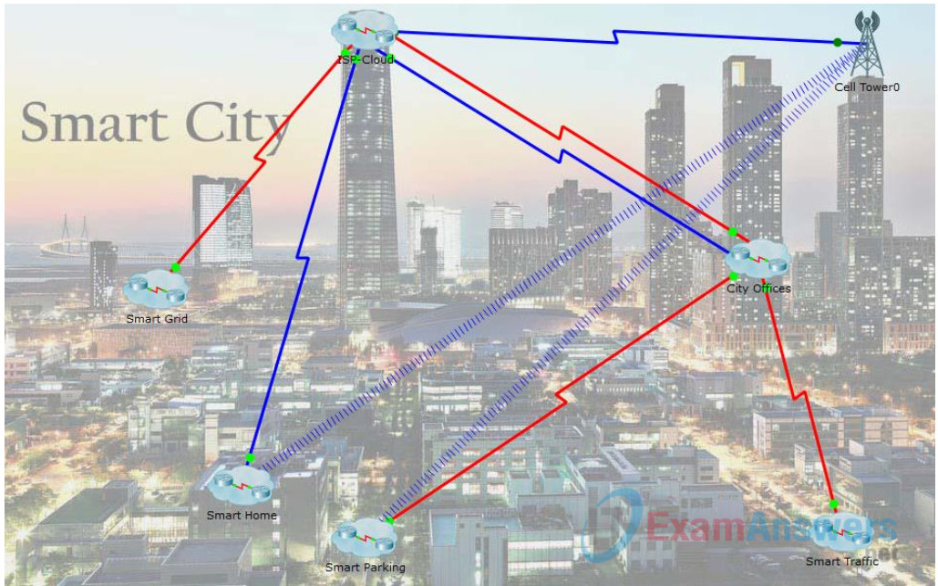
Topology

Objectives
- Explore a Smart City
- Analyze The Usage of Cloud Computing in the Smart City
Background / Scenario
In this activity, you will explore the smart city example. The idea of a smart city is based on the premise of a city which takes advantage of software to monitor and analyze various events and make decisions to improve the lives of its residents.
The smart city in this example has been broken down into clusters. Depending on the application, some data is best processed and monitored from a remote location. The Smart City Offices offer capabilities that allow a city administrator to monitor various events throughout the city.
Required Resource
- Packet Tracer 7.1 or newer.
Part 1: Explore the Smart City
Step 1: Understanding the devices that comprise the smart city
Because sensors and IoT devices are spread through the smart city, the proper network infrastructure must be in place before they can communicate. The Smart City is a metropolitan area network (MAN) comprised of smaller networks. These networks are often connected by WAN links which allow communication across large geographic distances. The ISP Cloud provides city wide access to various individuals and organizations.
a. Click the ISP Cloud and examine the resources that it offers to the city.
b. Click the back button. Which city networks are connected using the red serial cables?
Smart Grid and City Offices
Note: Packet Tracer labels connections between network devices but it can be turned off for the sake of readability. To turn labelling off, go to Options > Preferences > Interface Tab > uncheck Always Show Port Labels in Logical Workspace.
c. Which city networks are connected using the blue coaxial cables?
Cell Tower0, City Offices and Smart Home
d. Click the City Offices cluster. Why are there two connections leading to it from the ISP Cloud?
One is a router and the other is traffic control.
e. Click the back button. Which city networks are wirelessly connected to the Cell-Tower?
Smart Home, Smart Parking and City Offices.
f. Which devices in the Smart Home are connected to the Cell-Tower?
Tablet and smartphone.
g. Which devices in the Smart Parking cluster are connected to the Cell-Tower?
SmartPhone0 and S-Parking-RT
Part 2: Smart Parking
The Smart City is made up of a number of systems represented in this example by clusters. The Smart Parking cluster allows city officials and citizens to benefit from its IoT implementation.
Step 1: Interacting With the Smart Parking Cluster (City Offices Personnel)
The devices in the smart parking cluster can be monitored and controlled remotely through any computer in the city offices cluster. Because all smart parking cluster devices connect to the City IoT Server which hosts a web-based interface, tablets, smartphones, laptops or desktop computers can be used to interact with the smart devices.
a. Click the City IT Laptop in the City Offices cluster.
b. Navigate to Desktop > Web Browser.
c. In the URL address bar, type in 195.0.0.2. This is the IP address of the City IoT Server.
d. Use Park/Park as the username and password to log into the City IoT Server.
Note: You may have to a few minutes until the all the network devices become online and the parking meters can reach to IoT registration server.
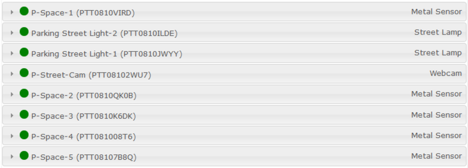
e. What is displayed?

f. The parking meters register themselves with the server and send status updates periodically. Click the P-Space-1 meter to expand it.
What is the value displayed?

g. Without closing the City IT Laptop window, go back to the smart parking cluster and click and drag the red car onto parking spot 1. Parking spot 1 is the leftmost parking spot in the cluster.
h. Go back to the City IT Laptop window and look for P-Space-1 (expand it if necessary).
What is the value displayed now?

The parking spaces sensors are PT metal sensors configured to respond to metal objects (the cars in this case) when placed close enough.
Step 2: Interacting With the Smart Parking Cluster (Regular Citizens)
a. While useful as a monitoring tool for city administration, regular citizens shouldn’t have access to the interface in the server. To allow citizens to monitor what parking spaces are available in a given street, another web page has been designed.
Close the City IT Laptop window and navigate back to the Smart Parking cluster.
b. Click the Smartphone and open its web browser by navigating to Desktop Tab > Web Browser.
c. Type in 10.10.10.10 in the address bar. 10.10.10.10 is the address of the parking server, represented by the PT-MCU.
Note: It may take a few seconds before the page loads in the smartphone’s web browser.
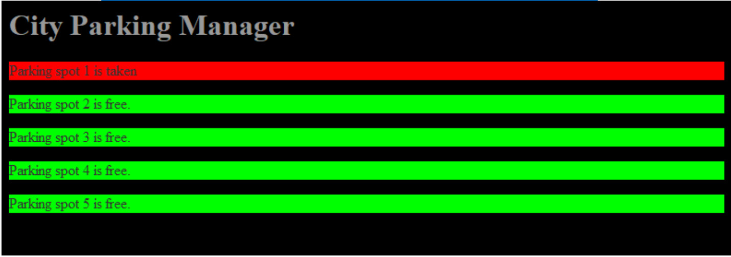
d. What do you see after the page loads?

e. Without closing the Smartphone’s window, drag the green car onto Parking Spot 5. Parking Spot 5 is the rightmost parking spot in the smart parking cluster.
f. Go back to smartphone’s window (the web browser should still be displaying the page loaded from the MCU parking server). What do you see after the page loads?

Note: It may take a few seconds before the page is updated.
g. The parking spots not only report to the IoT Registration Server hosted in the City Offices cluster, but also report to the local parking server. This allows for citizens to browse and learn about parking spot availability even before they get to the street.
h. Take some time to explore the code running in the Parking Server MCU.
Part 3: Smart Traffic
Another component of the smart city is Smart Traffic. In this example, Smart Traffic allows emergency vehicles such as ambulances or paramedics to communicate with the traffic light system and request free passage in case of an emergency. Navigate to the Smart Traffic cluster.
a. In this example Street Light 1 and Street Light 2 are playing the role of traffic lights. The paramedics are responding to an emergency. As the Paramedics vehicle gets closer to the traffic lights they turn green.
Click and drag the paramedic’s truck and place it closer to the traffic light on the right that is currently red.
b. What happens to the traffic light on the right?
Lights up in red
c. Move the paramedics away from the traffic light on the right and place it close to the red car.
What happens to the traffic light?
The light in the ambulance turns red and the light on the right turns green
d. The paramedics vehicle sends a message to the MCU controlling the traffic lights and requests passage. The MCU recognizes the paramedics as a legitimate emergency vehicle and grants it passage by turning the light green. The MCU also turns related lights red to ensure safe passage. When the emergency vehicle has passed safely, the MCU returns system back to its normal operation.
e. Take some time to analyze the code running in the MCU in the ambulance by navigating the Programming tab.
Note: You may need to click the Advanced button at the bottom of the devices’ windows before the Programming tab can be displayed.
Part 4: Reflection
When sensors, software and servers are interconnected, it is possible to gather data and monitor events. This allows decisions to be made based on event driven data. The key point of this example is to show that connected things can monitor and act if they are:
- Capable of executing programs.
- Connected to sensors or actuators.
- Connected to other devices via the network.
A regular chair for example, can be prepared to track and record the weight and number of every person who sits on it.
Part 5: Challenge (optional)
Design a smart chair that tracks and records the weight of people who sit on it. Questions that may guide you through the design process are:
- What parts do I need to make this project (sensors, MCUs, SBCs, cables, etc)?
- What language should I use to write the program?
- Do I need any Internet servers or Cloud subscriptions?
- Can I build a flowcharts of the software code execution as well as the device’s operation?
