6.3.1.11 Lab – Record sunrise and sunset in Google Calendar using IFTTT (Instructor Version)
Lab Topology

Objectives
- Learn how to leverage public cloud services to integrate machines with cloud applications
Background
In this lab you will learn how to offload the complexity of working with various cloud applications with an easy to use IFTTT (IF This Than That) script (applet). IFTTT is a public web service that enables creative control and automated interactions between various cloud based services like Twitter, Instagram, Facebook, Dropbox, Webex Teams, etc. The interactions are defined in IFTTT using small scripts called applets – as simple as “if” something happens, “then” trigger some action.
In this advanced lab, code implementation using the Visual Programming language might actually require an excessive amount of time to construct, therefore in this lab you will be writing a Python script directly.
Required Resources
- PL-Kit (Paspberry Pi and Redboard(Arduino Uno))
- Raspberry Pi properly configured to work with PL-App
- Wired Ethernet or Wi-Fi connection to the Internet with DHCP and no traffic filtering
- IFTTT account
- Google or Facebook account is OPTIONAL
Task 1: Setting up an IFTTT user account and the Maker channel
Step 1: Register a free user account at IFTTT
If you currently do not have an IFTTT user account, go to https://ifttt.com/join to get one for free. You could also use a Google account or Facebook account to complete this activity.
Step 2: Setup the Maker channel recipe integrating Google Calendar
Make sure you are signed in to either IFTTT, Google, or Facebook on the IFTTT.com website.
Click My Applets
![]()
Click New Applet

Create a Maker channel “this” part:

Search for the Webhooks service

Choose to receive a web request
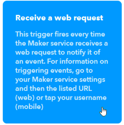
Specify the name of an event for the web request (you will use this name in the GET Request URL): For this application, the name of the event is “SunRise” and “SunSet” – the first one triggers a Sun Rise action, the second triggers the Sun Set action.
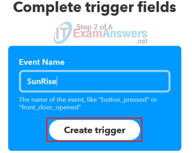
Continue by adding the “that” part of the recipe:

Search for Google Calendar to choose an action.
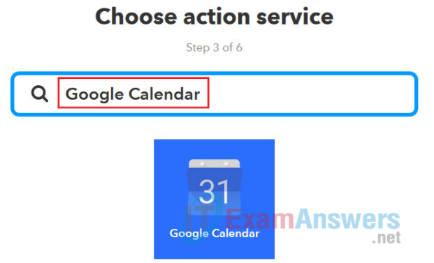
For the Google Calendar, select the Quick add event action.
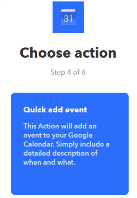
Specify the text of the Quick add event – this will be the text of an event created in your Google Calendar:
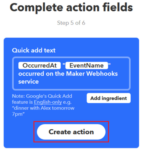
Complete the creation of the applet:
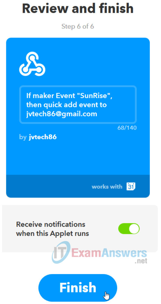
Do not forget to redo these all steps for the SunSet event.

Step 3: Getting the IFTTT Maker Channel’s Secret Key
Go to https://ifttt.com/maker_webhooks to get your Maker Channel’s secret Key:
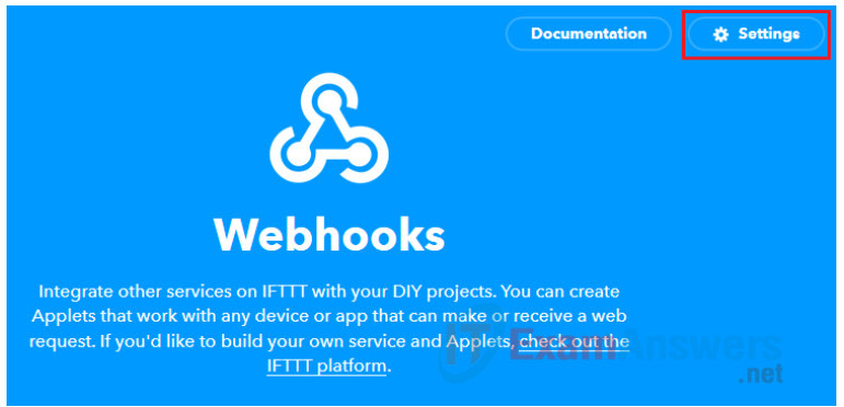
Click Settings to be shown the Maker Channel’s secret key.
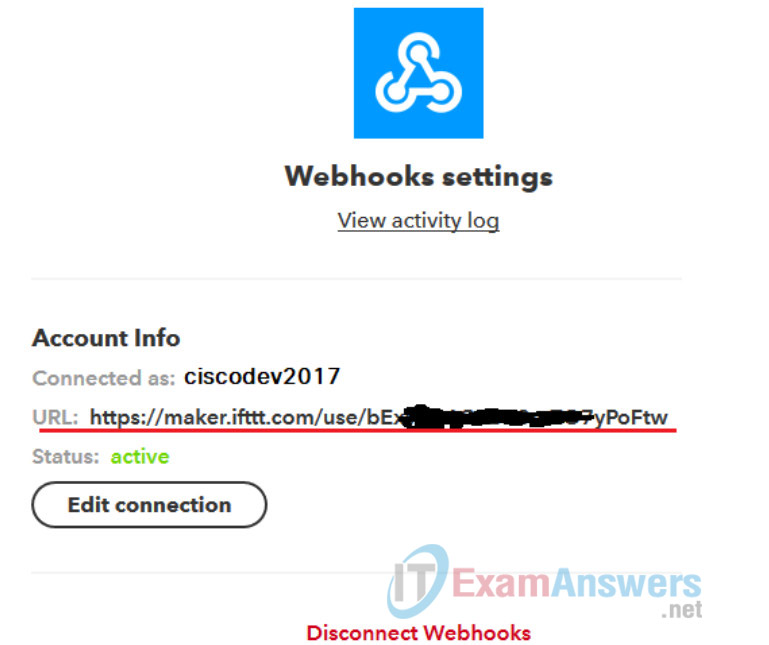
You will need the Maker Channel Secret Key every time you want to trigger an event by using an HTTP/S GET/POST URL: https://maker.ifttt.com/trigger/{event}/with/key/IBX_vJGs2xa3li6yOem***************MidP7vakzuQq where {event} is the event name you want to trigger (e.g. SunRise or SunSet) followed at the end of the URL with your Secure Key.
Task 2: Connecting the electronic circuits
Step 1: Using a voltage divider to connect a light sensor (photoresistor) to Arduino
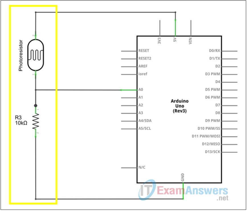
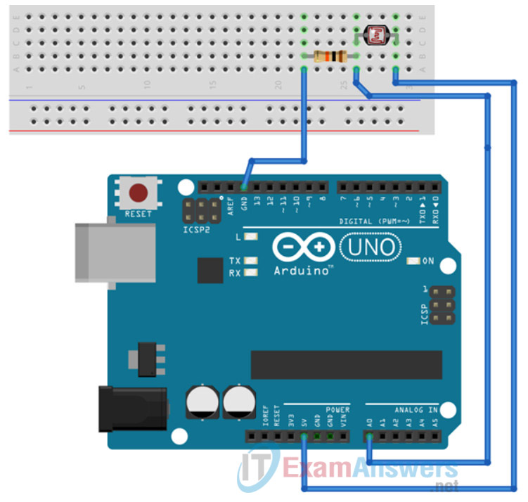
Using a breadboard, connect a photoresistor and one 10kOhm resistor. The junction point between the photoresistor and the resistor is connected to the analog A0 input pin of the Arduino board. The ground pin of the board is connected to the other side of the resistor, while the +5V pin of the board is connected to ther other side of the photoresistor. The more light comes to the head of the photoresistor, the less the resistivity it has. That means that with more light, the A0 analog input pin will measure higher voltage than in the dark conditions.
Arduino Schematics:
Arduino Physical Layout:
Step 2: Connect the Arduino with the Raspberry Pi
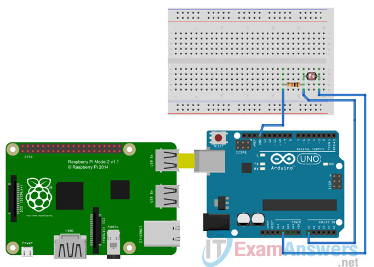
Using a USB cable, connect the Arduino to the Raspberry Pi. Since the Arduino is powered directly from this USB connection, there is no need to provide any additional power to the Arduino. Only provide power to the Raspberry Pi using the micro-USB port from an external power adapter. The USB cable between the Arduino and the Raspberry Pi is not only used to power the Arduino, but it also provides a serial communication channel to control and monitor the Arduino from applications running on the Raspberry Pi.
Raspberry Pi and Arduino:
Task 3: Software to connect to dots
Step 1: Setup
As seen on the previous task, the analog sensors, in our case a photoresistor, is connected to the Arduino board using the Analog Input pin number 0 (A0). Based on the light conditions above the photoresistos, the A0 pin will measure input Voltage values from 0 to +5V and transform it into its digital values from 0 to 1023.
Since the Arduino has no direct network connection, the data read by the A0 pin must be transfered to a Raspberry Pi board which is connected either to the local Wi-Fi or to the local Ethernet network. This connection is established using the USB cable between the Raspberry Pi and the Arduino. The same USB cable is used to power the Arduino board with the connected sensors, as well as to provide a serial transport channel between the Raspberry Pi and Arduino. The serial transport channel between the Arduino and Raspbery Pi in Linux is usually identified as a device in the /dev directory with a name ttyACM0 or ttyUSB0 (/dev/ttyACM0 or /dev/ttyUSB0).
To idenfity the specific serial device name, connect the Arduino to the Raspberry Pi using the USB cable and execute the following code on a Linux terminal to identify the Arduino’s serial device name:
%%bash
# ^^^ The commands below are to be executed as Linux Bash commands.
# You can get the same output by opening a terminal connection to the device and executing these commands manually.

dmesg | grep -v disconnect | grep -Eo "tty(ACM|USB)." | tail -1
A more advanced bash script that not only displays the serial device name, but the device details can be found and executed below:
%%bash
# ^^^ The commands below are to be executed as Linux Bash commands.
# You can get the same output by opening a terminal connection to the device and executing these commands manually.

for sysdevpath in $(find /sys/bus/usb/devices/usb*/ -name dev); do
    (
        syspath="${sysdevpath%/dev}"
        devname="$(udevadm info -q name -p $syspath)"
        [[ "$devname" == "bus/"* ]] && continue
        eval "$(udevadm info -q property --export -p $syspath)" 2>/dev/null
        [[ -z "$ID_SERIAL" ]] && continue
        echo "/dev/$devname - $ID_SERIAL"
    )
done
Once a Arduino’s serial device name has been identified, you can continue by implementing an Arduino serial communication protocol called Firmata. Firmata is a protocol for communicating with microcontrollers from software on a host computer. The protocol can be implemented in firmware on any microcontroller architecture as well as software on any host computer software package.
Firmata has Client Libraries supporting Python as well as multiple other programming languages. The Python library is called pyfirmata. To verify if this library is available on your system, execute the Python code in the cell below. The code will try to load the pyfirmata library on the local device. If no error is displayed, the pyfirmata library has been sucssessfully loaded into the Python process.
import pyfirmata
Having pyfirmata on the device enables it to use the firmata protocol to control the GPIO pins of the connected Arduino boards. To make sure the Arduino board understands the firmata protocol and can be controlled using firmata, you have to flash the firmata firmware to your Arduino board.
To do so, you can use the Python code in the cell below. Please update the code that will try to upload the firmware with the name of the Arduino’s serial device that you identified in the cell above: chestnut.arduino.flash_firmata(board='uno', port='/dev/ttyXXX', debug=True)
Please take a moment once you execute the cell below as it might take up to 1-2 minutes to flash the new firmare.
import chestnut.arduino

chestnut.arduino.flash_firmata(board='uno', port='/dev/ttyUSB0', debug=True)
#                                                      ^^^^^^ set this with the ttyACM0 or ttyUSB0 name of your Arduino device
To verify that the Firmata protocol is operational between the Raspberry Pi and the Arduino, use the following simple code to to import the required fuctions from the pyfirmata library and then setup a connection to an Arduino board, identified as a serial device from above.
arduinoBoard = pyfirmata.Arduino('/dev/ttyUSB0')
#                                      ^^^^^^ set this with the ttyACM0 or ttyUSB0 name of your Arduino device
Step 2: Verify board communication
A successfull execution of the cell above will set a an object variable arduinoBoard that is used to interact with the Arduino board.
The following code can be used to blink the Arduino’s onboard LED connected to GPIO PIN number 13. Executing this code verifies that the board communication is fully functional from our Python code.
Once it is verified that it works, stop the code in the cell, otherwise it will continue running forever, or at least until your device is restarted.
# Since we want to add some delay into the actual blinking, we must also import the `time` python library:
import time

arduinoBoard = pyfirmata.Arduino('/dev/ttyUSB0')
#                               ^^^^^^ set this with the ttyACM0 or ttyUSB0 name of your Arduino device

# Define local variables that will act as the digital output pins:
#  digital output pin number 13:
pin13 = arduinoBoard.get_pin("d:13:o")
#                                 ^ o = output, i = input
#                               ^ 13 = GPIO pin number
#                             ^ d = digital GPIO pin

time.sleep(.4)

while True:
    try:
        print ("ON")
        pin13.write(1)
        time.sleep(1)
        print ("OFF")
        pin13.write(0)
        time.sleep(1)
    except KeyboardInterrupt:
        pin13.write(0)
        break
Update the code in the cell above to double the frequency of the blinking LED.
Step 3: Reading data from analog sensors
The Python code below reads data from sensors that are connected to the analog input pins of the Arduino board.
The sensor data read directly from the board using the firmata protocol (analog_0.read()) are returned as float numbers in an interval <0.0 - 1.0>. These values are normalized to integers in an interval <0, 1023>.
arduinoBoard = pyfirmata.Arduino('/dev/ttyUSB0')
#                                 ^^^^^^ set this with the ttyACM0 or ttyUSB0 name of your Arduino device

# To use Arduino's analog ports, it is handy to start an iterator thread.
# Otherwise the board will keep sending data to your serial, until it overflows:
it = pyfirmata.util.Iterator(arduinoBoard)
it.start()

# Define local variables that will act as the analog input pins:
#  analog input pin number 0:
analog_0 = arduinoBoard.get_pin('a:0:i')
#                                    ^ i = input
#                                  ^ 0 = analog input pin number
#                                ^ a = analog input pin

# Let's start a never ending loop:
while True:
# where we try to read the analog input values:
    try:
        print (analog_0.read())
        analog_0_value = round((analog_0.read() or 0) * 1023)
        print ("analog input 0 = " + str(analog_0_value))
        time.sleep(0.5)
    except KeyboardInterrupt:
        break
To visualize sensor data, a chestnut.graph library provides the output in the form of a live graph.
The code below reads and visualizes data from the light sensor connected to analog input pin number 0:
import chestnut.graph as graph
import pyfirmata
import time

# Define a live graph to be displayed below this cell:
lightGraph = graph.Line(['Light'])

arduinoBoard = pyfirmata.Arduino('/dev/ttyUSB0')
#                                     ^^^^^^ set this with the ttyACM0 or ttyUSB0 name of your Arduino device

# To use Arduino's analog ports, it is handy to start an iterator thread.
# Otherwise the board will keep sending data to your serial, until it overflows:
it = pyfirmata.util.Iterator(arduinoBoard)
it.start()

# Define local variables that will act as the analog input pins:
#  analog input pin number 0 with a light sensor:
analog_0 = arduinoBoard.get_pin('a:0:i')
#                                    ^ i = input
#                                  ^ 0 = analog input pin number
#                                ^ a = analog input pin

# Let's start a never ending loop:
while True:
# where we try to read the analog input values:
    try:
        # light sensor values normalized to <0, 1023>
        light_value = round((analog_0.read() or 0) * 1023)
        # add a new point to a graph:
        lightGraph.update([light_value])
        time.sleep(0.5)
    except KeyboardInterrupt:
        break
Step 4: Send an IFTTT request from Python
To trigger an IFTTT event using the Maker ITFFF channel, you have to open an HTTP connection to https://maker.ifttt.com/trigger/{event}/with/key/d******PeZK2****** where {event} is the event name you want to trigger (e.g. SunRise or SunSet) followed at the end of the URL with your Secure Key.
Set the iFTTTMakerSecretKey variable to own IFTTT Maker Channel’s Secure Key.
In Python, the requests library provides functions to work with HTTP connections. In the code below, the requests.get(url) function is being used which expects as the url parameter a valid http addess where he will try to connect and download the content.
Passing the requests.get(url) fuction an URL pointing to the IFTTT Maker’s Channel URL to record the SunSet and SunRise will trigger the IFTTT procedures. Executing the code below should therefore record in your Google Calendar a SunRise event. Please execute the cell and verify it with on your Google Calendar:
import requests # web http requests library

# copy here your personal Maker Secret Key from https://ifttt.com/maker
#  e.g.: iFTTTMakerSecretKey = "lBX_vJGs2xa******************P7bakzuQq"
iFTTTMakerSecretKey = "lBX_vJGs2xa******************P7bakzuQq"

# The IFTTT Maker Channel URLs as configured in your IFTTT recipes for SunRise and SunSet
iFTTTSunRiseURL = "https://maker.ifttt.com/trigger/SunRise/with/key/" + iFTTTMakerSecretKey
iFTTTSunSetURL  = "https://maker.ifttt.com/trigger/SunSet/with/key/"  + iFTTTMakerSecretKey

r = requests.get(iFTTTSunRiseURL)
# if the status_code is different from 200, something went wrong:
print ("The resulting HTTP GET status code was " + str(r.status_code))
Step 5: Put it all together
The code in the cell below contains all the required parts to build a Python application that will read data on the RaspPi from analog sensors connected to Arduino boards using the firmata protocol. It will then process the sensor data and, if needed, trigger an HTTP request to IFTTT for additional automation.
Execute the code cell below and, while the code is running, cover and uncover the light sensor. Compare the values in the code cell output when the sensor is covered to the values when the sensor is not covered. If the threshold value is not approximately midway between the highest and lowest light level values, adjust the value of the lightSensorValueThreshold variable to make it so.
import pyfirmata  # RPi to Arduino over the Firmata serial communication library
import time       # time.sleep(int seconds)
import requests   # web http requests library

# copy here your personal Maker Secret Key from https://ifttt.com/maker
#  e.g.: iFTTTMakerSecretKey = "lBX_vJGs2xa******************P7bakzuQq"
iFTTTMakerSecretKey = "lBX_vJGs2xa******************P7bakzuQq"
# The IFTTT Maker Channel URLs as configured in your IFTTT recipes for SunRise and SunSet
iFTTTSunRiseURL = "https://maker.ifttt.com/trigger/SunRise/with/key/" + iFTTTMakerSecretKey
iFTTTSunSetURL  = "https://maker.ifttt.com/trigger/SunSet/with/key/"  + iFTTTMakerSecretKey

# set the initial value of the lightSensorValue variable which holds the value read from the sensor
lightSensorValue = 0
# threshold number differenciating light from dark - e.g. sunrise from sunset

lightSensorValueThreshold = 500

# define an Arduino board connected as a /dev/ttyXXXX device:
arduinoBoard = pyfirmata.Arduino('/dev/ttyUSB0')
#                               ^^^^^^ set this with the ttyACM0 or ttyUSB0 name of your Arduino device

# start the communication between the RPi and Arduino using the Firmata serial protocol
arduinoReader = pyfirmata.util.Iterator(arduinoBoard)
arduinoReader.start()

# map the lightSensorInputAnalogPin variable to a physical Analog (a) Pin Number 0 (0) as an Input (i)
lightSensorInputAnalogPin = arduinoBoard.get_pin("a:0:i")

# before reading the very first input values from the Arduino, wait at least one second
#  this is needed to initialize the communication, for once we read the input, the values are valid
time.sleep(1)

# this variable holds the value of previous state
previousStateOfLight = None
# loop forever
while True:
    # once we read the analog input pin value, normalize it from the returned values <0.0,1.0> to <0,1023>
    lightSensorValue = round((lightSensorInputAnalogPin.read() or 0) * 1023)
    print ("The current light value = " + str(lightSensorValue))
    # the ineresting logic starts here:
    #  once a threshold value is reached with the current measurement, check what was the previous state
    #  based on a previous state, if needed, trigger an action - update a calendar
    if(lightSensorValue > lightSensorValueThreshold):
        if(previousStateOfLight == False):
            print ("SunRise is here!")
            # using the requests library, execute an HTTP GET request for the specified URL
            r = requests.get(iFTTTSunRiseURL)
            # if the status_code is different from 200, something went wrong:
            print ("The resulting HTTP GET status code was " + str(r.status_code))
            # update the state of the previousStateOfLight variable with the current state
        previousStateOfLight = True
    else:
        if(previousStateOfLight == True):
            print ("SunSet is here!")
            # using the requests library, execute an HTTP GET request for the specified URL
            r = requests.get(iFTTTSunSetURL)
            # if the status_code is different from 200, something went wrong:
            print ("The resulting HTTP GET status code was " + str(r.status_code))
        # update the state of the previousStateOfLight variable with the current state
        previousStateOfLight = False
    # be nice - it is not worth to use the whole CPU just to have precisions at miliseconds level
    #  by running the loop itterations as fast as possible
    # pause this loop for at least one second
    time.sleep(1)
Open your Google Calendar at calendar.google.com. You should see multiple entries which allign with the entries above. When the light reaches a certain high threshold. A SunRise event is written to the Google Calendar. When the light reaches a certain low threshold, a SunSet event is written to the Google Calendar. I fyou are having trouble seing the events, click the Agenda button. You should see all the SunRise and SunSet events that occurred recently.
Step 6: Troubleshooting
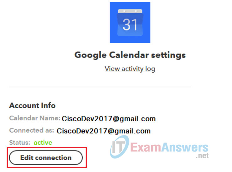
If you cannot see the entries, go to https://ifttt.com/google_calendar and click Settings
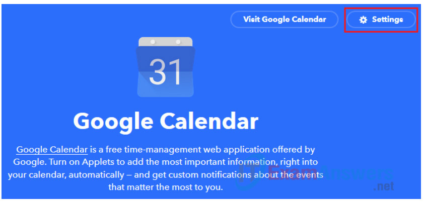
Click on Edit connection
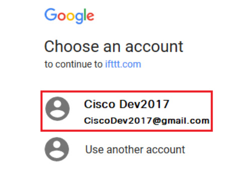
Click on the correct Google account
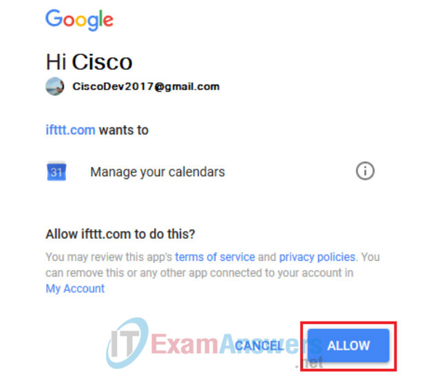
Click on Allow
Repeat the execution of the code in Step 5.
Reflection
What other IFTTT applications could the photoresistor setup be used for?
