2.1.3.4 Lab – Designing a Circuit from Start to Finish (Instructor Version)
Objectives
Part 1: Use a breadboard to design a circuit in Autodesk 123D Lab View
- Create an account
- Create a new Electronics Lab
- Add components using the + Components button
- Modify the circuit
Part 2: Design the printed circuit board using Autodesk 123D PCB View
- Design a final product
Background / Scenario
Autodesk 123D Circuits provides access to virtual electronics, allowing users to design, prototype, and order competed circuits. This activity will guide students through the process of building a custom circuit board.
Required Resources
- PC with Internet Access
- Autodesk 123D Account (Free)
Part 1: Use a breadboard to design a circuit in Autodesk 123D Lab View
Step 1: Create an account.
Navigate to https://123d.circuits.io/ and sign up for a free account.

Step 2: Create a new Electronics Lab.
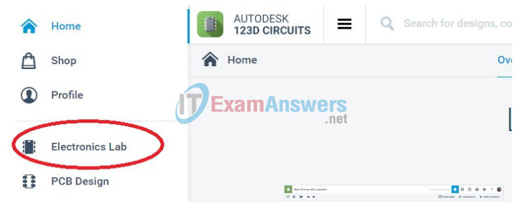
a. Select the icon consisting of three horizontal lines to access the menu.

b. Choose the Electronics Lab icon on the left side of the page.
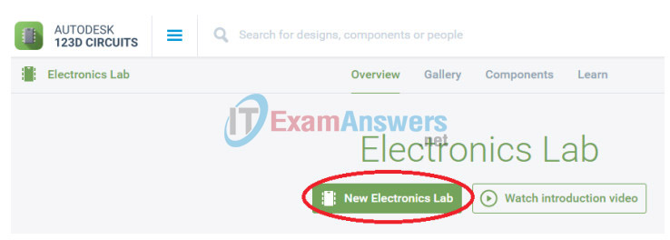
c. Select New Electronics Lab to reveal a breadboard.
Step 3: Add components using the + Components button.

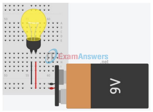
a. Select the 9V Battery in the components list, and place its terminals on the positive (+) and negative (-) rows at the bottom of the breadboard.
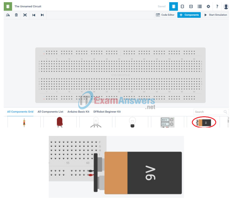
Note: Use the scroll wheel on the mouse to zoom in and out.
b. Select the Light Bulb from the components list and add it to the breadboard.
c. Draw two wires on the breadboard directly below the light bulb terminals by clicking once on the hole to start of the wire and then click a second time on the hole to end the wire. Use the Breadboardwire Color dropdown to change the wire color, select red for positive and black for negative.
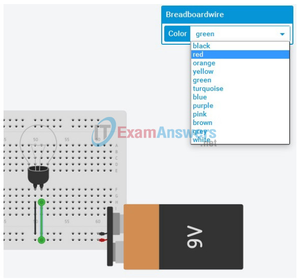
d. Use the Start Simulation button to turn on the light.
Step 4: Modify the circuit.
a. Delete the negative (black) wire from the circuit.
b. Add a second light next to the breadboard.
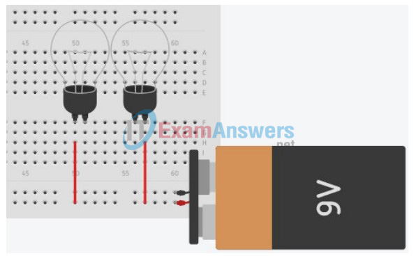
c. Draw a second red wire on the breadboard.
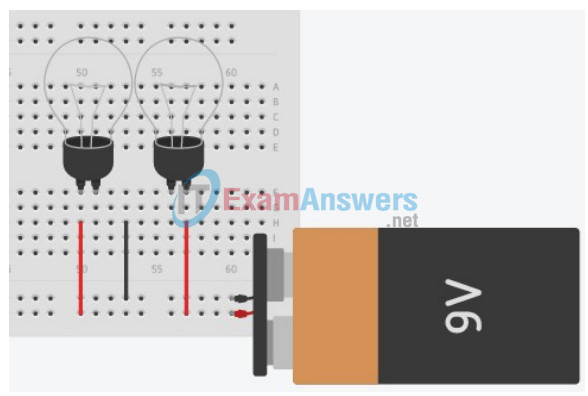
d. Create a new ground wire, negative wire, between the two lights. Color the wire black.
e. Add a Slideswitch component to the breadboard drawing, with the center prong in the same column as the black wire.
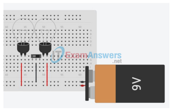
f. Draw wires connecting the slide switch to the columns of the negative terminals for the light bulbs.
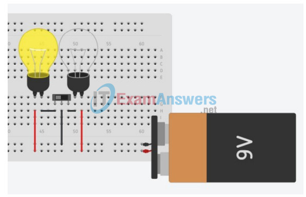
g. Use the Start Simulation button and toggle the Slideswitch by clicking on it. The switch should complete only one circuit at a time, turning each light on and off individually.
Part 2: Design the printed circuit board using Autodesk 123D PCB View
Step 1: Design a final product.
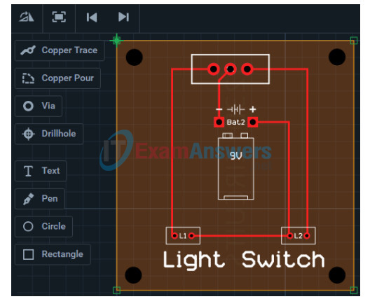
a. Select the PCB View Icon.
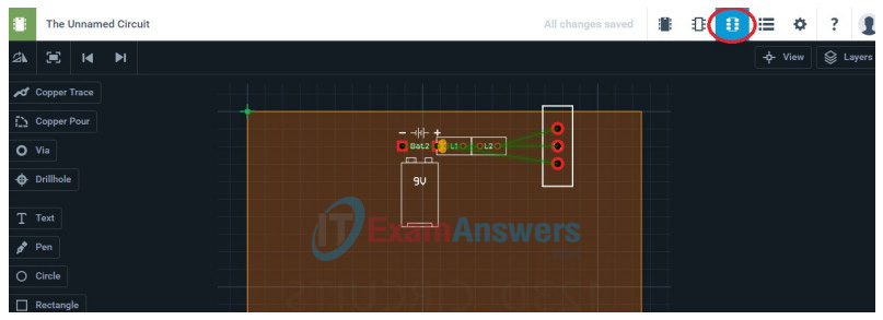
b. Rearrange the components to eliminate wire overlap.
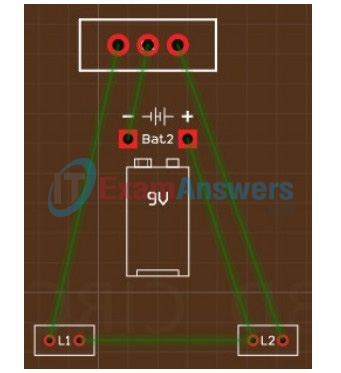
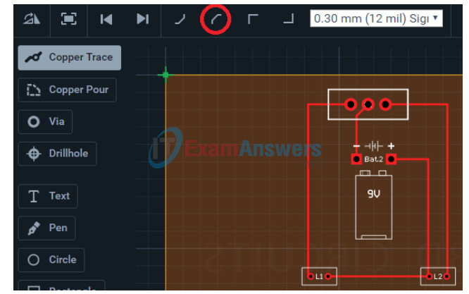
c. Replace each green connection with a copper trace wire. Use the icons at the top of the screen to control the wire angle.
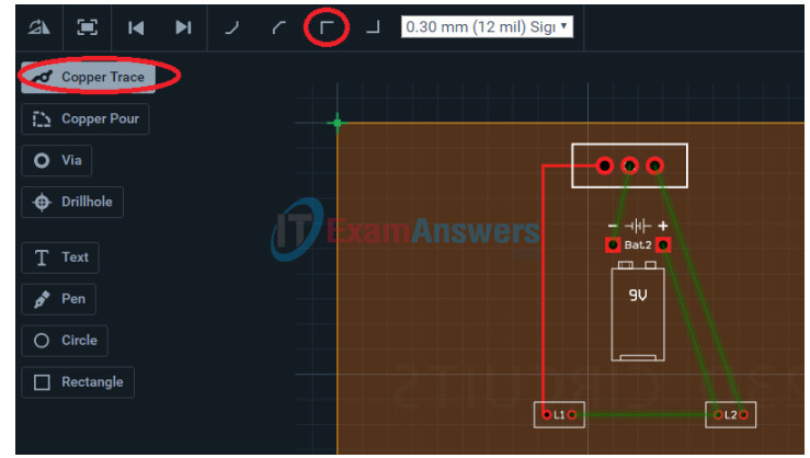
d. The com terminal (middle prong) on the Slideswitch will require an angled copper trace wire to avoid completing the circuit to the outer terminal prongs.
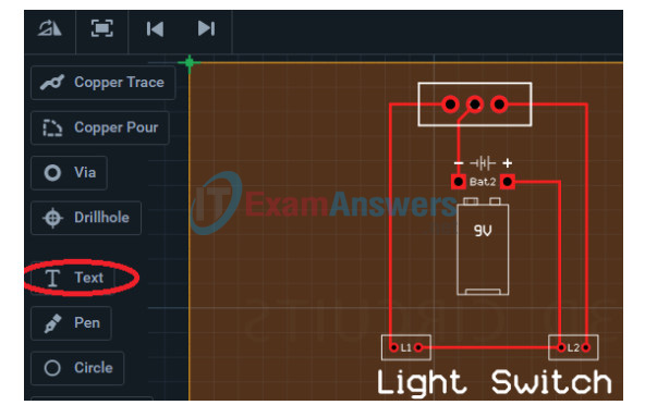
e. The circuit board can be labeled using the Text tool.
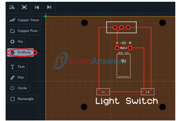
f. Drill mounting holes in the circuit board as needed.
g. Select the edge of the circuit board to change the dimensions.
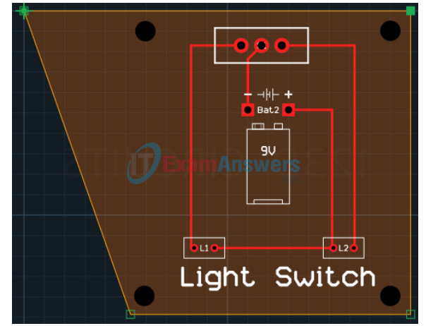
Note: The quoted price for creating a working board changes with its size.
h. Adjust the alignment grid from the upper left corner of the circuit board as needed.
Reflection
What would happen if a potentiometer replaced the slide switch in the drawing?
Same thing will happen in the circuit as potentiometer is also known to be a switch for the light bulbs. A potentiometer is additionally a three-terminal resistor with a sliding or turning contact that structures a movable voltage divider And, in that circumstance, there is just two terminals being utilized, assuming this is the case, one end and the wiper, goes about as a variable resistor or rheostat.
