2.2.2.5 Lab – Blinking an LED using RedBoard and Arduino IDE (Instructor Version)
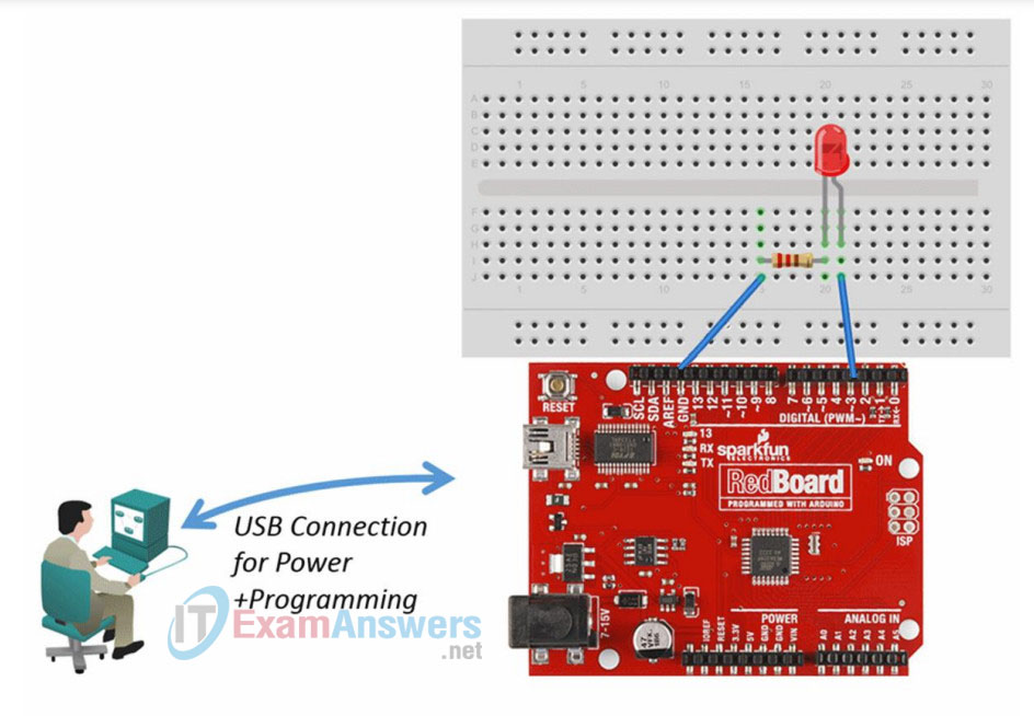
Topology
Objectives
Part 1: Setting up RedBoard
- Installing the Arduino IDE
- Connecting the RedBoard to the computer
- Configuring the Arduino IDE
- Blinking the LED on the RedBoard
Part 2: Connect an external LED using a breadboard
- Connecting the hardware
- Connect an external LED using a breadboard to the RedBoard
- Running the sketch
Background / Scenario
Arduino, with its open source hardware prototyping platform, started a revolution in the maker community. Access to electronics, control, and programming has dramatically simplified and revolutionized how “smart devices” are built. In this lab, you will learn to use the Arduino and Arduino IDE to make an LED blink.
Inside of the Sparkfun Inventors Kit you will find all the resources needed to start to prototype smart things. The Arduino compatible RedBoard is able to read inputs – a light on a sensor, a finger on a button, or a Twitter message – and turn it into an output – activating a motor, turning on an LED, or publishing something online. All this is defined by a set of instructions programmed through the Arduino Software (Arduino IDE).
Required Resources
- PC with Internet Access
- SparkFun Inventors Kit or comparable Arduino kit
- Breadboard / LED / 330 Ohm (Ω) resistor / wires
Part 1: Setting up Arduino
Step 1: Installing the Arduino IDE
Navigate to https://www.arduino.cc/en/Main/Software in your web browser, download and install the Arduino IDE software package. The software package contains the Integrated Development Environment (IDE) as well as the required drivers for the Arduino boards.

Note: Debian Linux users can enter sudo apt-get install arduino at a command prompt, followed by the appropriate password.
Step 2: Connecting the RedBoard to the computer.
a. Use the USB cable that was included in the SparkFun Inventors Kit to connect the RedBoard to the PC. The first time this is done, you should see Windows installing the device driver for the board.
Note: Linux users can type lsusb at the prompt to verify the connection to the RedBoard.
b. Using Windows Device Manager, verify that the board has been successfully installed as a Serial COM Port. You can start Windows Device Manager by using the Start > Run menu (quick tip: press the Win + R keys on your keyboard) and enter the devmgmt.msc command.

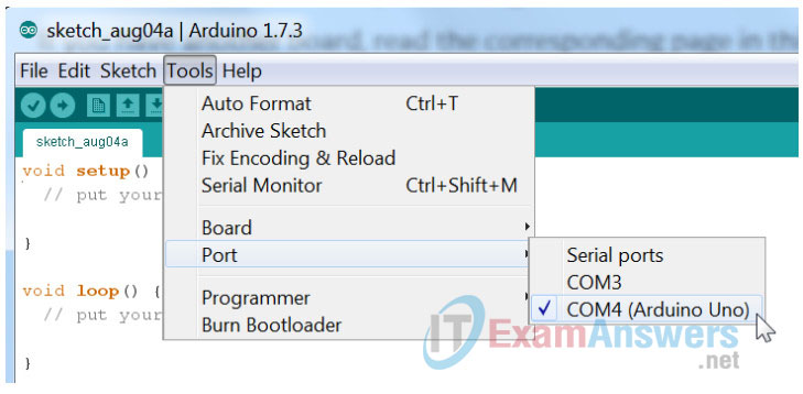
c. Record the COM port of the Arduino board for future reference. In this example, it is the COM4 port. The Serial COM port is used to communicate with the board from the PC. It is used to write new firmware to the microcontroller unit (MCU) as well as for debugging via a Serial Line Monitor.

Step 3: Configuring the Arduino IDE
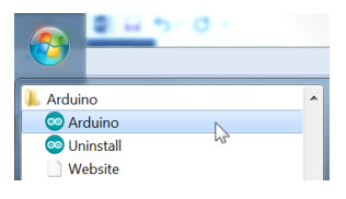
a. From the Start menu, start the Arduino IDE.
b. In the Arduino IDE, set the COM port of the RedBoard.
Note: Linux users will find that the Arduino IDE requires the addition of dialout group access to use /dev/ttyUSB0. For a genuine Arduino UNO board, the actual port that is used is /dev/ttyACM0. The number 0 identifies the first connected board. Additional USB connected boards will be identified with respective numbers such as 1, 2, 3, etc.
Step 4: Blinking the LED on the RedBoard
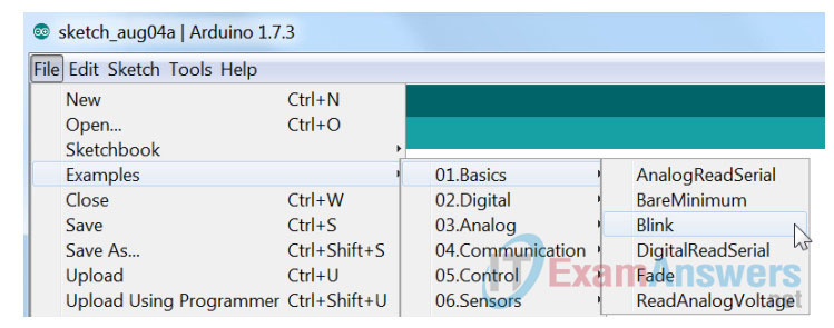
a. From the File menu, select the example sketch (the source code of your program) for blinking an LED.
Note: The syntax of the Arduino language used to write sketches is based on C/C++. If you are familiar with C, C++, JavaScript, or PHP, you should be able to quickly catch up. Even if you have no previous experience, the code is pretty self-explanatory. A complete language reference can be found at: https://www.arduino.cc/en/Reference/HomePage.
b. In the Blink sketch, examine the setup function using pin 13 as an output pin. This requires the use of the pinMode(PIN,Value) statement:
// the setup function runs once when you press reset or power the board
void setup() {
// initialize digital pin 13 as an output.
pinMode(13, OUTPUT);
}
Note: Lines beginning with // above indicate comments to help describe what is being done and ignored by the Arduino board.
Pin 13 is special as it has an LED attached directly on the RedBoard.

c. Predict the output of the loop function. The digitalWrite function sets the value of pin 13 to HIGH. A delay function will then pause the execution for 1000ms. The next use of the digitalWrite function will set pin 13 to LOW, followed by another delay of 1000ms. Upon completion the loop function executes again.
The loop will repeat until the RedBoard is turned off:
// the loop function runs over and over again forever
void loop() {
  digitalWrite(13, HIGH); //turn LED on (HIGH is the voltage level)
  delay(1000); //wait for a second
  digitalWrite(13, LOW); //turn LED off by making the voltage LOW
  delay(1000); //wait for a second
}
d. Verify and compile the sketch to create an executable firmware that can be uploaded to the flash memory of the microcontroller.
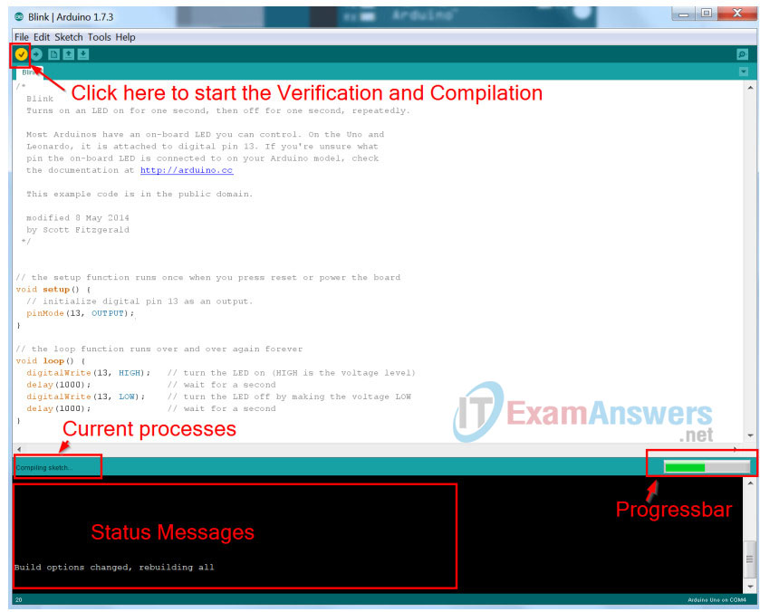
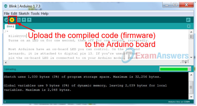
e. Upload the firmware to your RedBoard. After this step, you should see the onboard LED connected to pin 13 blinking in a 1 second interval.
How can you change the blinking rate?
By changing the delay speeds, users can make the LED blink at any desired speed.
Part 2: Connect an external LED using a breadboard
Step 1: Connecting the hardware.
a. Identify the GPIO pins and the analog input pins on the following picture of the RedBoard.
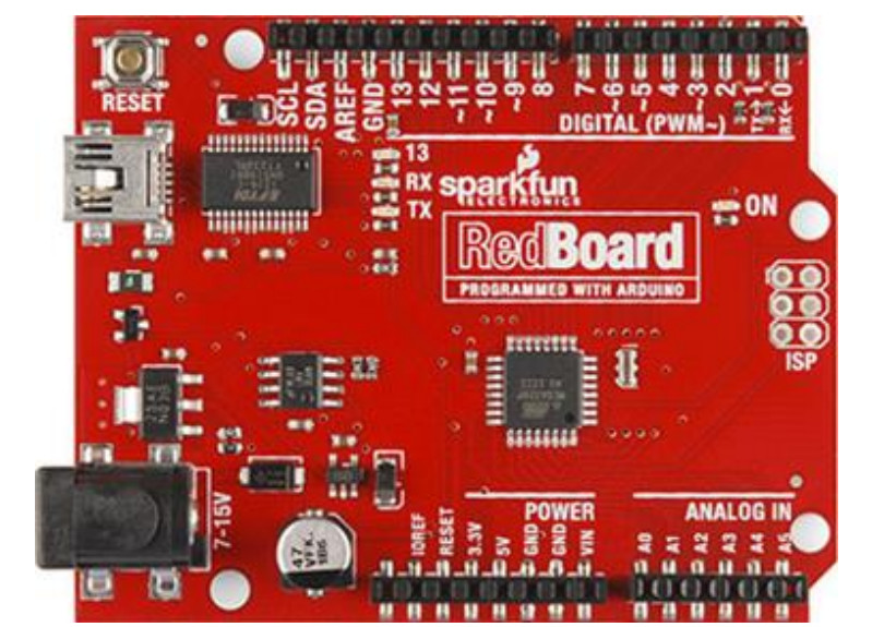
Step 2: Connect an external LED using a breadboard to the Arduino.
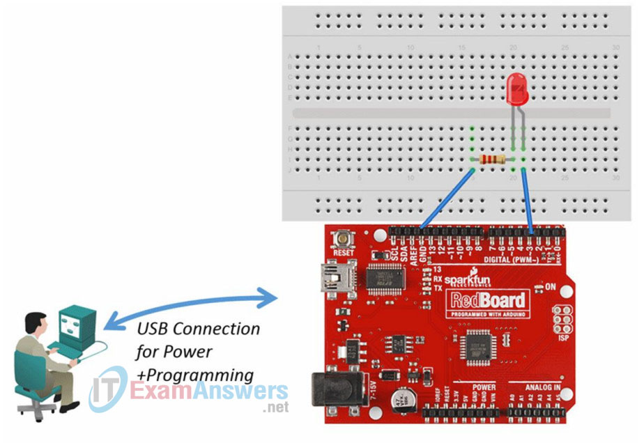
a. Using an LED, jumper cables, and a breadboard, connect the RedBoard to the LED. The logical schematic is outlined in the figure below. The LED is to be connected to GPIO pin number 3.
Note: It is very important to connect the +5V cable to the breadboard last. Connecting the power to the breadboard at any other time may result in damage or destruction to the Arduino board.
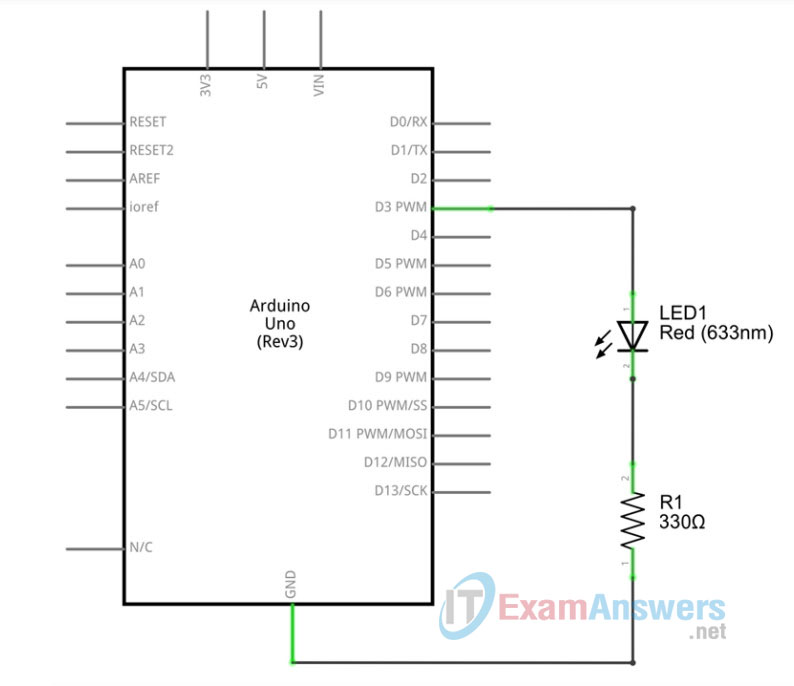
The LED has two legs: one is called anode, while other one is called cathode. To light up the LED, charge the anode to about +2V and the cathode to the Ground (0V). The anode leg is generally longer than the cathode leg but it is not a standard. On the other hand, the cathode leg is always connected to the bigger part inside the LED.

The resistor which is serially connected to the cathode side of the LED is used to prevent too high of a current from flowing through the circuit. An LED requires about 15mA of current and 2V to light up. RedBoard provides 5V on each GPIO pin. Directly connecting the LED could result in burning the LED, because of the high voltage and resulting current, or in some situations even damaging the RedBoard.
b. Search for a 330Ω resistor in the Sparkfun Inventors Kit. Connect the LED, resistor, and jumper cables as shown on the physical diagram above to a breadboard and to an RedBoard. The physical connections are outlined in the figure below.
Step 3: Running the software
a. Update the previous Blink sketch code in the Arduino IDE to blink the LED on the GPIO pin number 3.
b. Verify, compile, and upload the code to the RedBoard. When done you should see the LED blinking.
Reflection
What issues could cause the failure of the LED to blink?
The LED could be wired backwards. Pin 3 was not used, or the circuit was not properly grounded. The software was not updated to indicate pin 3. Or a bug was introduced into the software.
