
Lab - Configure NAT for IPv4 (Instructor Version)
Topology
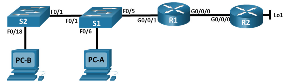
Addressing Table
| Device | Interface | IP Address | Subnet Mask |
|---|---|---|---|
| R1 | G0/0/0 | 209.165.200.230 | 255.255.255.248 |
| G0/0/1 | 192.168.1.1 | 255.255.255.0 | |
| R2 | G0/0/0 | 209.165.200.225 | 255.255.255.248 |
| Lo1 | 209.165.200.1 | 255.255.255.224 | |
| S1 | VLAN 1 | 192.168.1.11 | 255.255.255.0 |
| S2 | VLAN 1 | 192.168.1.12 | 255.255.255.0 |
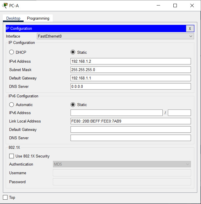
| PC-A | NIC | 192.168.1.2 | 255.255.255.0 |
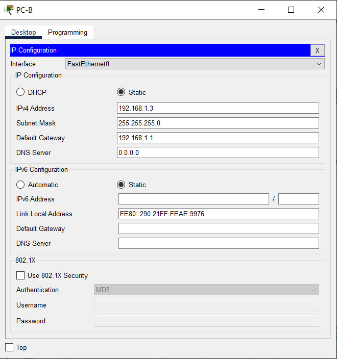
| PC-B | NIC | 192.168.1.3 | 255.255.255.0 |
Objectives
- Part 1: Build the Network and Configure Basic Device Settings
- Part 2: Configure and verify NAT for IPv4
- Part 3: Configure and verify PAT for IPv4
- Part 4: Configure and verify Static NAT for IPv4
Background / Scenario
Network Address Translation (NAT) is the process where a network device, such as a Cisco router, assigns a public address to host devices inside a private network. The main reason to use NAT is to reduce the number of public IP addresses that an organization uses because the number of available IPv4 public addresses is limited.
An ISP has allocated the public IP address space of 209.165.200.224/29 to a company. This network is used to address the link between the ISP router (R2) and the company gateway (R1). The first address (209.165.200.225) is assigned to the g0/0/0 interface on R2 and the last address (209.165.200.230) is assigned to the g0/0/0 interface on R1. The remaining addresses (209.165.200.226-209.165.200.229) will be used to provide internet access to the company hosts. A default route is used from R1 to R2. The internet is simulated by a loopback address on R2.
In this lab, you will configure various types of NAT. You will test, view, and verify that the translations are taking place, and you will interpret the NAT/PAT statistics to monitor the process.
Note: The routers used with CCNA hands-on labs are Cisco 4221 with Cisco IOS XE Release 16.9.3 (universalk9 image). The switches used in the labs are Cisco Catalyst 2960s with Cisco IOS Release 15.2(2) (lanbasek9 image). Other routers, switches, and Cisco IOS versions can be used. Depending on the model and Cisco IOS version, the commands available and the output produced might vary from what is shown in the labs. Refer to the Router Interface Summary Table at the end of the lab for the correct interface identifiers.
Note: Ensure that the routers and switches have been erased and have no startup configurations. If you are unsure contact your instructor.
Instructor Note: Refer to the Instructor Lab Manual for the procedures to initialize and reload devices.
Required Resources
- 2 Routers (Cisco 4221 with Cisco IOS XE Release 16.9.4 universal image or comparable)
- 2 Switches (Cisco 2960 with Cisco IOS Release 15.2(2) lanbasek9 image or comparable)
- 2 PCs (Windows with a terminal emulation program, such as Tera Term)
- Console cables to configure the Cisco IOS devices via the console ports
- Ethernet cables as shown in the topology
Instructions
Part 1: Build the Network and Configure Basic Device Settings
In Part 1, you will set up the network topology and configure basic settings on the PC hosts and switches.
Step 1: Cable the network as shown in the topology.
Attach the devices as shown in the topology diagram and cable as necessary.
Step 2: Configure basic settings for each router.
a. Assign a device name to the router.
router(config)# hostname R1
b. Disable DNS lookup to prevent the router from attempting to translate incorrectly entered commands as though they were host names.
R1(config)# no ip domain-lookup
c. Assign class as the privileged EXEC encrypted password.
R1(config)# enable secret class
d. Assign cisco as the console password and enable login.
R1(config)# line console 0
R1(config-line)# password cisco
R1(config-line)# login
e. Assign cisco as the VTY password and enable login.
R1(config)# line vty 0 4
R1(config-line)# password cisco
R1(config-line)# login
f. Encrypt the plaintext passwords.
R1(config)# service password-encryption
g. Create a banner that warns anyone accessing the device that unauthorized access is prohibited.
R1(config)# banner motd $ Authorized Users Only! $
h. Configure interface IP addressing as specified in the table above.
R1(config)# interface g0/0/0
R1(config-if)# ip address 209.165.200.230 255.255.255.248
R1(config-if)# no shutdown
R1(config-if)# interface g0/0/1
R1(config-if)# ip address 192.168.1.1 255.255.255.0
R1(config-if)# no shutdown
R1(config-if)# exit
i. Configure a default route to R2 from R1.
R1(config)# ip route 0.0.0.0 0.0.0.0 209.165.200.225
j. Save the running configuration to the startup configuration file.
R1(config)# exit
R1# copy running-config startup-config
On router R2:
router(config)# hostname R2

R2(config)# no ip domain-lookup

R2(config)# enable secret class

R2(config)# line console 0
R2(config-line)# password cisco
R2(config-line)# login

R2(config-line)# line vty 0 4
R2(config-line)# password cisco
R2(config-line)# login

R2(config-line)# service password-encryption

R2(config)# banner motd $ Authorized Users Only! $

R2(config)# interface g0/0/0
R2(config-if)# ip address 209.165.200.225 255.255.255.248
R2(config-if)# no shutdown
R2(config-if)# interface loopback 1
R2(config-if)# ip address 209.165.200.1 255.255.255.224
R2(config-if)# no shutdown
R2(config-if)# end

R2# copy running-config startup-config
Step 3: Configure basic settings for each switch.
a. Assign a device name to the switch.
switch(config)# hostname S1
b. Disable DNS lookup to prevent the router from attempting to translate incorrectly entered commands as though they were host names.
S1(config)# no ip domain-lookup
c. Assign class as the privileged EXEC encrypted password.
S1(config)# enable secret class
d. Assign cisco as the console password and enable login.
S1(config)# line console 0
S1(config-line)# password cisco
S1(config-line)# login
e. Assign cisco as the VTY password and enable login.
S1(config)# line vty 0 15
S1(config-line)# password cisco
S1(config-line)# login
f. Encrypt the plaintext passwords.
S1(config)# service password-encryption
g. Create a banner that warns anyone accessing the device that unauthorized access is prohibited.
S1(config)# banner motd $ Authorized Users Only! $
h. Shutdown all interfaces that will not be used.
S1(config)# interface range f0/2-4, f0/7-24, g0/1-2
S1(config-if-range)# shutdown
i. Configure interface IP addressing as specified in the table above.
S1(config)# interface vlan 1
S1(config-if)# ip address 192.168.1.11 255.255.255.0
S1(config-if)# no shutdown
S1(config-if)# exit
S1(config)# ip default-gateway 192.168.1.1
j. Save the running configuration to the startup configuration file.
S1# copy running-config startup-config
On Switch S2:
switch(config)# hostname S2

S2(config)# no ip domain-lookup

S2(config)# enable secret class

S2(config)# line console 0
S2(config-line)# password cisco
S2(config-line)# login

S2(config-line)# line vty 0 15
S2(config-line)# password cisco
S2(config-line)# login

S2(config-line)# service password-encryption

S2(config)# banner motd $ Authorized Users Only! $

S2(config)# interface range f0/2-17, f0/19-24, g0/1-2
S2(config-if-range)# shutdown

S2(config)# interface vlan 1
S2(config-if)# ip address 192.168.1.12 255.255.255.0
S2(config-if)# no shutdown
S2(config-if)# exit
S2(config)# ip default-gateway 192.168.1.1
S2(config)# end

S2# copy running-config startup-config
Configure IP addresses for PC-A and PC-B:
Part 2: Configure and verify NAT for IPv4
In Part 2, you will configure and verify NAT for IPv4.
Step 1: Configure NAT on R1 using a pool of three addresses, 209.165.200.226-209.165.200.228.
a. Configure a simple access list that defines what hosts are going to be allowed for translation. In this case, all devices on the R1 LAN are eligible for translation.
R1(config)# access-list 1 permit 192.168.1.0 0.0.0.255
b. Create the NAT pool, and give it a name and a range of addresses to use.
R1(config)# ip nat pool PUBLIC_ACCESS 209.165.200.226 209.165.200.228 netmask 255.255.255.248
Note: The netmask parameter is not an IP address delimiter. It should be the correct subnet mask for the addresses being assigned, even if you are not using all the subnet addresses in the pool.
c. Configure the translation, associating the ACL and Pool to the translation process.
R1(config)# ip nat inside source list 1 pool PUBLIC_ACCESS
Note: Three very important points. First, the word ‘inside’ is critical to the operation of this kind of NAT. If you omit it, NAT will not work. Second, the list number is the ACL number configured in a previous step. Third, the pool name is case-sensitive.
d. Define the inside interface.
R1(config)# interface g0/0/1
R1(config-if)# ip nat inside
e. Define the outside interface.
R1(config)# interface g0/0/0
R1(config-if)# ip nat outside
Step 2: Test and Verify the configuration.
a. From PC-B, ping the Lo1 interface (209.165.200.1) on R2. If the ping was unsuccessful, troubleshoot and correct the issues. On R1, display the NAT table on R1 with the command show ip nat translations.
R1# show ip nat translations
Pro  Inside global         Inside local          Outside local         Outside global
---  209.165.200.226       192.168.1.3           ---                   ---
icmp 209.165.200.226:1     192.168.1.3:1         209.165.200.1:1       209.165.200.1:1
Total number of translations: 2
What was the inside local address of PC-B translated to?
209.165.200.226
What type of NAT address is the translated address?
Inside Global
b. From PC-A, ping the Lo1 interface (209.165.200.1) on R2. If the ping was unsuccessful, troubleshoot and correct the issues. On R1, display the NAT table on R1 with the command show ip nat translations.
R1# show ip nat translations
Pro  Inside global         Inside local          Outside local         Outside global
---  209.165.200.227       192.168.1.2           ---                   ---
---  209.165.200.226       192.168.1.3           ---                   ---
icmp 209.165.200.227:1     192.168.1.2:1         209.165.200.1:1       209.165.200.1:1
icmp 209.165.200.226:1     192.168.1.3:1         209.165.200.1:1       209.165.200.1:1
Total number of translations: 4
c. Notice that the previous translation for PC-B is still in the table. From S1, ping the Lo1 interface (209.165.200.1) on R2. If the ping was unsuccessful, troubleshoot and correct the issues. On R1, display the NAT table on R1 with the command show ip nat translations.
R1# show ip nat translations
Pro  Inside global         Inside local          Outside local         Outside global
---  209.165.200.227       192.168.1.2           ---                   ---
---  209.165.200.226       192.168.1.3           ---                   ---
---  209.165.200.228       192.168.1.11          ---                   ---
icmp 209.165.200.226:1     192.168.1.3:1         209.165.200.1:1       209.165.200.1:1
icmp 209.165.200.228:0     192.168.1.11:0        209.165.200.1:0       209.165.200.1:0
Total number of translations: 5
d. Now try and ping R2 Lo1 from S2. This time, the translations fail, and you get these messages (or similar) on the R1 console:
Sep 23 15:43:55.562: %IOSXE-6-PLATFORM: R0/0: cpp_cp: QFP:0.0 Thread:000 TS:00000001473688385900 %NAT-6-ADDR_ALLOC_FAILURE: Address allocation failed; pool 1 may be exhausted [2]
e. This is an expected result, because only 3 addresses are allocated, and we tried to ping Lo1 from four devices. Recall that NAT is a one-to-one translation. So how long are the translations allocated? Issue the command show ip nat translations verbose and you will see that the answer is for 24 hours.
R1# show ip nat translations verbose
Pro  Inside global         Inside local          Outside local         Outside global
---  209.165.200.226       192.168.1.3           ---                   ---
  create: 09/23/19 15:35:27, use: 09/23/19 15:35:27, timeout: 23:56:42
  Map-Id(In): 1
<output omitted>
f. Given that the pool is limited to three addresses, NAT to a pool of addresses is not adequate for our application. Clear the NAT translations and statistics and we will move on to PAT.
R1# clear ip nat translations *
R1# clear ip nat statistics
Part 3: Configure and verify PAT for IPv4
In Part 3, you will configure replace NAT with PAT to a pool of addresses, and then with PAT using an interface.
Step 1: Remove the translation command on R1.
The components of an Address Translation configuration are basically the same; something (an access-list) to identify addresses eligible to be translated, an optionally configured pool of addresses to translate them to, and the commands necessary to identify the inside and outside interfaces. From Part 1, our access-list (access-list 1) is still correct for the network scenario, so there is no need to recreate it. We are going to use the same pool of addresses, so there is no need to recreate that configuration either. Also, the inside and outside interfaces are not changing. To get started in Part 3, remove the command that ties the ACL and pool together.
R1(config)# no ip nat inside source list 1 pool PUBLIC_ACCESS
Step 2: Add the PAT command on R1.
Now, configure for PAT translation to a pool of addresses (remember, the ACL and Pool are already configured, so this is the only command we need to change from NAT to PAT).
R1(config)# ip nat inside source list 1 pool PUBLIC_ACCESS overload
Step 3: Test and Verify the configuration.
a. Let’s verify PAT is working. From PC-B, ping the Lo1 interface (209.165.200.1) on R2. If the ping was unsuccessful, troubleshoot and correct the issues. On R1, display the NAT table on R1 with the command show ip nat translations.
R1# show ip nat translations
Pro  Inside global         Inside local          Outside local         Outside global
icmp 209.165.200.226:1     192.168.1.3:1         209.165.200.1:1       209.165.200.1:1
Total number of translations: 1#
What was the inside local address of PC-B translated to?
209.165.200.226
What type of NAT address is the translated address?
Inside Global
What is different about the output of the show ip nat translations command from the NAT exercise?
Answers may vary. There is no dedicated translation between an inside and outside address listed.
b. From PC-A, ping the Lo1 interface (209.165.200.1) on R2. If the ping was unsuccessful, troubleshoot and correct the issues. On R1, display the NAT table on R1 with the command show ip nat translations.
R1# show ip nat translations
Pro  Inside global         Inside local          Outside local         Outside global
icmp 209.165.200.226:1     192.168.1.2:1         209.165.200.1:1       209.165.200.1:1
Total number of translations: 1
Notice that there is only one translation again. Send the ping once more, and quickly go back to the router and issue the command show ip nat translations verbose and you will see what happened.
R1# show ip nat translations verbose
Pro  Inside global         Inside local          Outside local         Outside global
icmp 209.165.200.226:1     192.168.1.2:1         209.165.200.1:1       209.165.200.1:1
  create: 09/23/19 16:57:22, use: 09/23/19 16:57:25, timeout: 00:01:00
<output omitted>
As you can see, the translation timeout has been dropped from 24 hours to 1 minute.
c. Generate traffic from multiple devices to observe PAT. On PC-A and PC-B, use the -t parameter with the ping command to send a non-stop ping to R2’s Lo1 interface (ping -t 209.165.200.1), then go back to R1 and issue the show ip nat translations command:
R1# show ip nat translations
Pro  Inside global         Inside local          Outside local         Outside global
icmp 209.165.200.226:1     192.168.1.2:1         209.165.200.1:1       209.165.200.1:1
icmp 209.165.200.226:2     192.168.1.3:1         209.165.200.1:1       209.165.200.1:2
Total number of translations: 2
Notice that the inside global address is the same for both sessions.
How does the router keep track of what replies go where?
Unique Port Numbers are assigned.
d. PAT to a pool is a very effective solution for small-to-midsize organizations. However, there are unused IPv4 addresses involved in this scenario. We will move to PAT with interface overload to eliminate this waste of IPv4 addresses. Stop the pings on PC-A and PC-B with the Control-C key combination, then clear translations and translation statistics:
R1# clear ip nat translations *
R1# clear ip nat statistics
Step 4: On R1, remove the nat pool translation commands.
Once again, our access-list (access-list 1) is still correct for the network scenario, so there is no need to recreate it. Also, the inside and outside interfaces are not changing. To get started with PAT to an interface, clean up the configuration by removing the NAT Pool and the command that ties the ACL and pool together.
R1(config)# no ip nat inside source list 1 pool PUBLIC_ACCESS overload
R1(config)# no ip nat pool PUBLIC_ACCESS
Step 5: Add the PAT overload command by specifying the outside interface.
Add the PAT command that will cause overload to the outside interface.
R1(config)# ip nat inside source list 1 interface g0/0/0 overload
Step 6: Test and Verify the configuration.
a. Let’s verify PAT to the interface is working. From PC-B, ping the Lo1 interface (209.165.200.1) on R2. If the ping was unsuccessful, troubleshoot and correct the issues. On R1, display the NAT table on R1 with the command show ip nat translations.
R1# show ip nat translations
Pro  Inside global         Inside local          Outside local         Outside global
icmp 209.165.200.230:1     192.168.1.3:1         209.165.200.1:1       209.165.200.1:1
Total number of translations: 1
b. Generate traffic from multiple devices to observe PAT. On PC-A and PC-B, use the -t parameter with the ping command to send a non-stop ping to R2’s Lo1 interface (ping -t 209.165.200.1). On S1 and S2, issue the privileged exec command ping 209.165.200.1 repeat 2000. Then go back to R1 and issue the show ip nat translations command.
R1# show ip nat translations
Pro  Inside global         Inside local          Outside local         Outside global
icmp 209.165.200.230:3     192.168.1.11:1        209.165.200.1:1       209.165.200.1:3
icmp 209.165.200.230:2     192.168.1.2:1         209.165.200.1:1       209.165.200.1:2
icmp 209.165.200.230:4     192.168.1.3:1         209.165.200.1:1       209.165.200.1:4
icmp 209.165.200.230:1     192.168.1.12:1        209.165.200.1:1       209.165.200.1:1
Total number of translations: 4
Now all the Inside Global addresses are mapped to the g0/0/0 interface IP address.
Stop all the pings. On PC-A and PC-B, using the CTRL-C key combination.
Part 4: Configure and verify Static NAT for IPv4
In Part 4, you will configure static NAT so that PC-A is directly reachable from the internet. PC-A will be reachable from R2 via the address 209.165.200.229.
Note: The configuration you are about to complete does not follow recommended practices for internet-connected gateways. This lab completely omits what would be standard security practices to focus on successful configuration of static NAT. In a production environment, careful coordination between the network infrastructure and security teams would be fundamental to supporting this requirement.
Step 1: On R1, clear current translations and statistics.
R1# clear ip nat translations *
R1# clear ip nat statistics
Step 2: On R1, configure the NAT command required to statically map an inside address to an outside address.
For this step, configure a static mapping between 192.168.1.2 and 209.165.200.229 using the following command:
R1(config)# ip nat inside source static 192.168.1.2 209.165.200.229
Step 3: Test and Verify the configuration.
a. Let’s verify the Static NAT is working. On R1, display the NAT table on R1 with the command show ip nat translations, and you should see the static mapping.
R1# show ip nat translations
Pro  Inside global         Inside local          Outside local         Outside global
---  209.165.200.229       192.168.1.2           ---                   ---
Total number of translations: 1
b. The translation table shows the static translation is in effect. Verify this by pinging from R2 to 209.165.200.229. The pings should work.
Note: you may have to disable the PC firewall for the pings to work.
c. On R1, display the NAT table on R1 with the command show ip nat translations, and you should see the static mapping and the port-level translation for the inbound pings.
R1# show ip nat translations
Pro  Inside global         Inside local          Outside local         Outside global
---  209.165.200.229       192.168.1.2           ---                   ---
icmp 209.165.200.229:3     192.168.1.2:3         209.165.200.225:3     209.165.200.225:3
Total number of translations: 2
This validates that the Static NAT is working.
Router Interface Summary Table
| Router Model | Ethernet Interface #1 | Ethernet Interface #2 | Serial Interface #1 | Serial Interface #2 |
|---|---|---|---|---|
| 1800 | Fast Ethernet 0/0 (F0/0) | Fast Ethernet 0/1 (F0/1) | Serial 0/0/0 (S0/0/0) | Serial 0/0/1 (S0/0/1) |
| 1900 | Gigabit Ethernet 0/0 (G0/0) | Gigabit Ethernet 0/1 (G0/1) | Serial 0/0/0 (S0/0/0) | Serial 0/0/1 (S0/0/1) |
| 2801 | Fast Ethernet 0/0 (F0/0) | Fast Ethernet 0/1 (F0/1) | Serial 0/1/0 (S0/1/0) | Serial 0/1/1 (S0/1/1) |
| 2811 | Fast Ethernet 0/0 (F0/0) | Fast Ethernet 0/1 (F0/1) | Serial 0/0/0 (S0/0/0) | Serial 0/0/1 (S0/0/1) |
| 2900 | Gigabit Ethernet 0/0 (G0/0) | Gigabit Ethernet 0/1 (G0/1) | Serial 0/0/0 (S0/0/0) | Serial 0/0/1 (S0/0/1) |
| 4221 | Gigabit Ethernet 0/0/0 (G0/0/0) | Gigabit Ethernet 0/0/1 (G0/0/1) | Serial 0/1/0 (S0/1/0) | Serial 0/1/1 (S0/1/1) |
| 4300 | Gigabit Ethernet 0/0/0 (G0/0/0) | Gigabit Ethernet 0/0/1 (G0/0/1) | Serial 0/1/0 (S0/1/0) | Serial 0/1/1 (S0/1/1) |
Note: To find out how the router is configured, look at the interfaces to identify the type of router and how many interfaces the router has. There is no way to effectively list all the combinations of configurations for each router class. This table includes identifiers for the possible combinations of Ethernet and Serial interfaces in the device. The table does not include any other type of interface, even though a specific router may contain one. An example of this might be an ISDN BRI interface. The string in parenthesis is the legal abbreviation that can be used in Cisco IOS commands to represent the interface.
Device Configs - Final
Router R1
! ==============================================================
!--- Lab - Configure NAT for IPv4 (hands-on / real-equipment lab, Cisco 4221 + IOS XE 16.9)
!--- ANSWER SCRIPT FOR ROUTER R1
!--- Usage: from the console on R1, enter privileged EXEC mode with "enable", then work
!--- through this file IN ORDER. Every line beginning with "!" is a comment; IOS ignores it.
!--- This lab walks through THREE different NAT approaches in sequence on the same router -
!--- pool-based NAT (Part 2), pool-based PAT (Part 3a), then interface-based PAT (Part 3b) -
!--- each replacing the previous one via explicit "no" commands, before Part 4 adds a static
!--- mapping alongside the final interface-based PAT. Confirmed against this lab's own final
!--- "show run" Device Config.
! ==============================================================

enable
configure terminal

! --------------------------------------------------------------
!--- Part 1, Step 2: basic device settings + interface addressing + default route to R2.
! --------------------------------------------------------------
hostname R1
no ip domain-lookup
enable secret class

line console 0
 password cisco
 login
exit

line vty 0 4
 password cisco
 login
exit

service password-encryption
banner motd $ Authorized Users Only! $

interface GigabitEthernet0/0/0
 ip address 209.165.200.230 255.255.255.248
 no shutdown
exit

interface GigabitEthernet0/0/1
 ip address 192.168.1.1 255.255.255.0
 no shutdown
exit

ip route 0.0.0.0 0.0.0.0 209.165.200.225

end
copy running-config startup-config
configure terminal

! --------------------------------------------------------------
!--- Part 2, Step 1: NAT to a 3-address pool. ACL 1 and this pool stay defined for the rest
!--- of the lab (only the "ip nat inside source ..." binding gets swapped out later).
! --------------------------------------------------------------
access-list 1 permit 192.168.1.0 0.0.0.255
ip nat pool PUBLIC_ACCESS 209.165.200.226 209.165.200.228 netmask 255.255.255.248
ip nat inside source list 1 pool PUBLIC_ACCESS

interface GigabitEthernet0/0/1
 ip nat inside
exit

interface GigabitEthernet0/0/0
 ip nat outside
exit

! ==============================================================
!--- Part 2 verification:
!---   PC-B, then PC-A, then S1 > ping 209.165.200.1 (R2's Loopback1) -> first 3 succeed,
!---   each taking one of the pool's 3 addresses
!---   R1# show ip nat translations -> inside global 209.165.200.226/227/228 mapped 1:1 to
!---   192.168.1.3 / .2 / .11 respectively (PC-B, PC-A, S1)
!---   S2 > ping 209.165.200.1 -> FAILS (pool exhausted - only 3 addresses for 4 devices);
!---   R1's console logs a "NAT-6-ADDR_ALLOC_FAILURE" message
!---   R1# show ip nat translations verbose -> each entry's timeout is 24 hours by default
! ==============================================================

! --------------------------------------------------------------
!--- Part 2, Step 6 / Part 3, Step 1-2: swap pool-based NAT for pool-based PAT. Only the
!--- binding line changes - ACL 1 and the pool itself are untouched and reused as-is.
! --------------------------------------------------------------
clear ip nat translation *
clear ip nat statistics

configure terminal
no ip nat inside source list 1 pool PUBLIC_ACCESS
ip nat inside source list 1 pool PUBLIC_ACCESS overload
end

! ==============================================================
!--- Part 3a verification:
!---   PC-B > ping 209.165.200.1 -> succeeds; R1# show ip nat translations shows only ONE
!---   entry this time (no separate static-style "---" row - overload entries are always
!---   port-qualified)
!---   Ping again quickly and check "show ip nat translations verbose" -> timeout has
!---   dropped from 24 hours to 1 minute
!---   PC-A and PC-B > ping -t 209.165.200.1 (continuous) -> R1# show ip nat translations
!---   now shows both sharing the SAME inside global address (209.165.200.226), each
!---   distinguished by a different port number
! ==============================================================

! --------------------------------------------------------------
!--- Part 3, Step 4-5: swap pool-based PAT for interface-based PAT overload - no separate
!--- pool of addresses needed at all now; everything overloads onto G0/0/0's own address.
! --------------------------------------------------------------
clear ip nat translation *
clear ip nat statistics

configure terminal
no ip nat inside source list 1 pool PUBLIC_ACCESS overload
no ip nat pool PUBLIC_ACCESS
ip nat inside source list 1 interface GigabitEthernet0/0/0 overload
end

! ==============================================================
!--- Part 3b verification:
!---   PC-B > ping 209.165.200.1 -> succeeds; translated to 209.165.200.230 (G0/0/0's own
!---   address) instead of a separate pool address
!---   PC-A, PC-B (continuous pings) + S1, S2 (ping 209.165.200.1 repeat 2000, from EXEC
!---   mode) -> R1# show ip nat translations now shows all 4 devices (PC-A, PC-B, S1, S2)
!---   sharing 209.165.200.230, each with a distinct port
! ==============================================================

! --------------------------------------------------------------
!--- Part 4, Step 1-2: clear everything again, then add a permanent static mapping for
!--- PC-A so it's reachable FROM the internet side at a fixed address - this coexists with
!--- the interface-based PAT overload above rather than replacing it.
!--- NOTE: the lab's own prose for this step says to map "192.168.1.11 and 209.165.200.1" -
!--- but that's S1's management address and R2's own Loopback (the simulated internet
!--- itself), neither of which matches this lab's actual goal. The real command immediately
!--- below - and the lab's own final Device Config - both confirm the correct mapping is
!--- PC-A's real address (192.168.1.2) to the specifically allocated static public address
!--- (209.165.200.229), matching the stated requirement ("PC-A will be reachable from R2 via
!--- the address 209.165.200.229") and the later verification step (pinging 209.165.200.229
!--- from R2).
! --------------------------------------------------------------
clear ip nat translation *
clear ip nat statistics

configure terminal
ip nat inside source static 192.168.1.2 209.165.200.229
end

copy running-config startup-config

! ==============================================================
!--- Part 4 verification:
!---   R1# show ip nat translations -> one static entry: inside global 209.165.200.229,
!---   inside local 192.168.1.2 (Pro column blank - static, no port)
!---   R2# ping 209.165.200.229 -> succeeds
!---   R1# show ip nat translations (again, after R2's ping) -> the static row is joined by
!---   a port-level icmp entry for that same exchange, confirming the static mapping is
!---   actively translating real traffic
! ==============================================================
Router R2
! ==============================================================
!--- Lab - Configure NAT for IPv4 (hands-on / real-equipment lab)
!--- ANSWER SCRIPT FOR ROUTER R2
!--- Usage: from the console on R2, enter privileged EXEC mode with "enable", then paste
!--- this whole file. Every line beginning with "!" is a comment; IOS ignores it.
!--- R2 plays "the ISP" in this topology - it needs no NAT of its own, just its two
!--- addresses (the shared WAN link, and Loopback1 simulating a destination out on the
!--- internet).
! ==============================================================

enable
configure terminal

hostname R2
no ip domain-lookup
enable secret class

line console 0
 password cisco
 login
exit

line vty 0 4
 password cisco
 login
exit

service password-encryption
banner motd $ Authorized Users Only! $

interface GigabitEthernet0/0/0
 ip address 209.165.200.225 255.255.255.248
 no shutdown
exit

interface Loopback1
 ip address 209.165.200.1 255.255.255.224
exit

end
copy running-config startup-config

! ==============================================================
!--- Verification:
!---   R2# ping 209.165.200.230 (R1's G0/0/0) -> succeeds
!---   Later (Part 4): R2# ping 209.165.200.229 -> succeeds once R1's static NAT for PC-A
!---   is in place
! ==============================================================
Switch S1
! ==============================================================
!--- Lab - Configure NAT for IPv4 (hands-on / real-equipment lab, Cisco 2960 + IOS 15.2)
!--- ANSWER SCRIPT FOR SWITCH S1
!--- Usage: from the console on S1, enter privileged EXEC mode with "enable", then paste
!--- this whole file. Every line beginning with "!" is a comment; IOS ignores it.
!--- S1 connects PC-A (F0/6), the trunk-free link to S2 (F0/1), and R1 (F0/5) - every other
!--- port gets shut down.
!--- NEEDS CORRECTION: this lab's own walkthrough instructs "ip address 192.168.1.12" for
!--- S1's VLAN 1 - but that's S2's address. Both the topology diagram and the Addressing
!--- Table clearly show S1 = 192.168.1.11 and S2 = 192.168.1.12, and this lab's own final
!--- Device Config for S1 confirms .11 is the correct, actually-deployed value (identifiable
!--- by F0/6 - PC-A's port - being the one left active in that block). Use .11 here, not the
!--- .12 shown in the walkthrough text.
! ==============================================================

enable
configure terminal

hostname S1
no ip domain-lookup
enable secret class

line console 0
 password cisco
 login
exit

line vty 0 15
 password cisco
 login
exit

service password-encryption
banner motd $ Authorized Users Only! $

! --------------------------------------------------------------
!--- Shut down every port except F0/1 (to S2), F0/5 (to R1), and F0/6 (PC-A).
! --------------------------------------------------------------
interface range f0/2-4, f0/7-24, g0/1-2
 shutdown
exit

interface vlan 1
 ip address 192.168.1.11 255.255.255.0
 no shutdown
exit

ip default-gateway 192.168.1.1

end
copy running-config startup-config

! ==============================================================
!--- Verification:
!---   S1# show ip interface brief -> Vlan1 shows 192.168.1.11, up/up
!---   S1# ping 192.168.1.1 (R1) -> succeeds
!---   Later (Part 3b): S1# ping 209.165.200.1 repeat 2000 (from privileged EXEC) is used to
!---   generate test traffic through R1's interface-based PAT
! ==============================================================
Switch S2
! ==============================================================
!--- Lab - Configure NAT for IPv4 (hands-on / real-equipment lab, Cisco 2960 + IOS 15.2)
!--- ANSWER SCRIPT FOR SWITCH S2
!--- Usage: from the console on S2, enter privileged EXEC mode with "enable", then paste
!--- this whole file. Every line beginning with "!" is a comment; IOS ignores it.
!--- S2 connects PC-B (F0/18) and the link to S1 (F0/1) - every other port gets shut down.
! ==============================================================

enable
configure terminal

hostname S2
no ip domain-lookup
enable secret class

line console 0
 password cisco
 login
exit

line vty 0 15
 password cisco
 login
exit

service password-encryption
banner motd $ Authorized Users Only! $

! --------------------------------------------------------------
!--- Shut down every port except F0/1 (to S1) and F0/18 (PC-B).
! --------------------------------------------------------------
interface range f0/2-17, f0/19-24, g0/1-2
 shutdown
exit

interface vlan 1
 ip address 192.168.1.12 255.255.255.0
 no shutdown
exit

ip default-gateway 192.168.1.1

end
copy running-config startup-config

! ==============================================================
!--- Verification:
!---   S2# show ip interface brief -> Vlan1 shows 192.168.1.12, up/up
!---   S2# ping 192.168.1.1 (R1) -> succeeds
!---   Later (Part 3b): S2# ping 209.165.200.1 repeat 2000 (from privileged EXEC) is used to
!---   generate test traffic through R1's interface-based PAT
! ==============================================================


