
11.5.5 Packet Tracer – Subnet an IPv4 Network Instructor Version
Topology
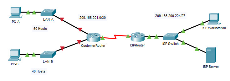
11.5.5 Packet Tracer - Subnet an IPv4 Network
Addressing Table
| Device | Interface | IP Address | Subnet Mask | Default Gateway |
|---|---|---|---|---|
| CustomerRouter | G0/0 | 192.168.0.1 | 255.255.255.192 | N/A |
| G0/1 | 192.168.0.65 | 255.255.255.192 | N/A | |
| S0/1/0 | 209.165.201.2 | 255.255.255.252 | N/A | |
| LAN-A Switch | VLAN1 | 192.168.0.2 | 255.255.255.192 | 192.168.0.1 |
| LAN-B Switch | VLAN1 | 192.168.0.66 | 255.255.255.192 | 192.168.0.65 |
| PC-A | NIC | 192.168.0.62 | 255.255.255.192 | 192.168.0.1 |
| PC-B | NIC | 192.168.0.126 | 255.255.255.192 | 192.168.0.65 |
| ISPRouter | G0/0 | 209.165.200.225 | 255.255.255.224 | N/A |
| S0/1/0 | 209.165.201.1 | 255.255.255.252 | N/A | |
| ISPSwitch | VLAN1 | 209.165.200.226 | 255.255.255.224 | 209.165.200.225 |
| ISP Workstation | NIC | 209.165.200.235 | 255.255.255.224 | 209.165.200.225 |
| ISP Server | NIC | 209.165.200.240 | 255.255.255.224 | 209.165.200.225 |
Objectives
- Part 1: Design an IPv4 Network Subnetting Scheme
- Part 2: Configure the Devices
- Part 3: Test and Troubleshoot the Network
Background / Scenario
In this activity, you will subnet the Customer network into multiple subnets. The subnet scheme should be based on the number of host computers required in each subnet, as well as other network considerations, like future network host expansion.
After you have created a subnetting scheme and completed the table by filling in the missing host and interface IP addresses, you will configure the host PCs, switches and router interfaces.
After the network devices and host PCs have been configured, you will use the ping command to test for network connectivity.
Instructions
Part 1: Design an IPv4 Network Subnetting Scheme
Step 1: Create a subnetting scheme that meets the required number of subnets and required number of host addresses.
In this scenario, you are a network technician assigned to install a new network for a customer. You must create multiple subnets out of the 192.168.0.0/24 network address space to meet the following requirements:
a. The first subnet is the LAN-A network. You need a minimum of 50 host IP addresses.
b. The second subnet is the LAN-B network. You need a minimum of 40 host IP addresses.
c. You also need at least two additional unused subnets for future network expansion.
Note: Variable length subnet masks will not be used. All of the device subnet masks should be the same length.
d. Answer the following questions to help create a subnetting scheme that meets the stated network requirements:
Questions:
How many host addresses are needed in the largest required subnet?
50
What is the minimum number of subnets required?
The requirements stated above specify two company networks plus two additional networks for future expansion. So, the answer is a minimum of four networks.
The network that you are tasked to subnet is 192.168.0.0/24. What is the /24 subnet mask in binary?
11111111.11111111.11111111.00000000
e. The subnet mask is made up of two portions, the network portion, and the host portion. This is represented in the binary by the ones and the zeros in the subnet mask.
Questions:
In the network mask, what do the ones represent?
The ones represent the network portion.
In the network mask, what do the zeros represent?
The zeroes represent the host portion.
f. To subnet a network, bits from the host portion of the original network mask are changed into subnet bits. The number of subnet bits defines the number of subnets.
Questions:
Given each of the possible subnet masks depicted in the following binary format, how many subnets and how many hosts are created in each example?
Hint: Remember that the number of host bits (to the power of 2) defines the number of hosts per subnet (minus 2), and the number of subnet bits (to the power of two) defines the number of subnets. The subnet bits (shown in bold) are the bits that have been borrowed beyond the original network mask of /24. The /24 is the prefix notation and corresponds to a dotted decimal mask of 255.255.255.0.
1) (/25) 11111111.11111111.11111111.10000000
Dotted decimal subnet mask equivalent:
255.255.255.128
Number of subnets? Number of hosts?
Two subnets (2^1) and 128 hosts (2^7) - 2 = 126 hosts per subnet
2) (/26) 11111111.11111111.11111111.11000000
Dotted decimal subnet mask equivalent:
255.255.255.192
Number of subnets? Number of hosts?
Four subnets (2^2) and 64 hosts (2^6) - 2 = 62 hosts per subnet
3) (/27) 11111111.11111111.11111111.11100000
Dotted decimal subnet mask equivalent:
255.255.255.224
Number of subnets? Number of hosts?
Eight subnets (2^3) and 32 hosts (2^5) - 2 = 30 hosts per subnet
4) (/28) 11111111.11111111.11111111.11110000
Dotted decimal subnet mask equivalent:
255.255.255.240
Number of subnets? Number of hosts?
Sixteen subnets (2^4) and 16 hosts (2^4) - 2 = 14 hosts per subnet
5) (/29) 11111111.11111111.11111111.11111000
Dotted decimal subnet mask equivalent:
255.255.255.248
Number of subnets? Number of hosts?
Thirty-two subnets (2^5) and 8 hosts (2^3) - 2 = 6 hosts per subnet
6) (/30) 11111111.11111111.11111111.11111100
Dotted decimal subnet mask equivalent:
255.255.255.252
Number of subnets? Number of hosts?
Sixty-four subnets (2^6) and 4 hosts (2^2) - 2 = 2 hosts per subnet
Considering your answers above, which subnet masks meet the required number of minimum host addresses?
/25, /26
Considering your answers above, which subnet masks meets the minimum number of subnets required?
/26, /27, /28, /29, /30 will give the required number of subnets.
Considering your answers above, which subnet mask meets both the required minimum number of hosts and the minimum number of subnets required?
/26 will give you the four subnets that are required, and 62 hosts per subnet, which is greater than the 50 hosts required for the first subnet.
When you have determined which subnet mask meets all of the stated network requirements, derive each of the subnets. List the subnets from first to last in the table. Remember that the first subnet is 192.168.0.0 with the chosen subnet mask.
| Subnet Address | Prefix | Subnet Mask |
|---|---|---|
| 192.168.0.0 | /26 | 255.255.255.192 |
| 192.168.0.64 | /26 | 255.255.255.192 |
| 192.168.0.128 | /26 | 255.255.255.192 |
| 192.168.0.192 | /26 | 255.255.255.192 |
Step 2: Fill in the missing IP addresses in the Addressing Table
Assign IP addresses based on the following criteria: Use the ISP Network settings as an example.
a. Assign the first subnet to LAN-A.
- Use the first host address for the CustomerRouter interface connected to LAN-A switch.
- Use the second host address for the LAN-A switch. Make sure to assign a default gateway address for the switch.
- Use the last host address for PC-A. Make sure to assign a default gateway address for the PC.
b. Assign the second subnet to LAN-B.
- Use the first host address for the CustomerRouter interface connected to LAN-B switch.
- Use the second host address for the LAN-B switch. Make sure to assign a default gateway address for the switch.
- Use the last host address for PC-B. Make sure to assign a default gateway address for the PC.
Part 2: Configure the Devices
Configure basic settings on the PCs, switches, and router. Refer to the Addressing Table for device names and address information.
Step 1: Configure CustomerRouter.
a. Set the enable secret password on CustomerRouter to Class123.
Router(config)# enable secret Class123
b. Set the console login password to Cisco123.
Router(config)# line console 0
Router(config-line)# password Cisco123
Router(config-line)# login
c. Configure CustomerRouter as the hostname for the router.
Router(config)# hostname CustomerRouter
d. Configure the G0/0 and G0/1 interfaces with IP addresses and subnet masks, and then enable them.
CustomerRouter(config)# interface gigabitethernet 0/0
CustomerRouter(config-if)# ip address 192.168.0.1 255.255.255.192
CustomerRouter(config-if)# no shutdown
CustomerRouter(config-if)# interface gigabitethernet 0/1
CustomerRouter(config-if)# ip address 192.168.0.65 255.255.255.192
CustomerRouter(config-if)# no shutdown
e. Save the running configuration to the startup configuration file.
CustomerRouter# copy running-config startup-config
Step 2: Configure the two customer LAN switches.
Configure the IP addresses on interface VLAN 1 on the two customer LAN switches. Make sure to configure the correct default gateway on each switch.
Switch(config)# interface vlan 1
Switch(config-if)# ip address 192.168.0.2 255.255.255.192
Switch(config-if)# no shutdown
Switch(config-if)# exit
Switch(config)# ip default-gateway 192.168.0.1
Switch(config)# interface vlan 1
Switch(config-if)# ip address 192.168.0.66 255.255.255.192
Switch(config-if)# no shutdown
Switch(config-if)# exit
Switch(config)# ip default-gateway 192.168.0.65
Step 3: Configure the PC interfaces.
Configure the IP address, subnet mask, and default gateway settings on PC-A and PC-B.
Part 3: Test and Troubleshoot the Network
In Part 3, you will use the ping command to test network connectivity.
a. Determine if PC-A can communicate with its default gateway. Do you get a reply?
C:\> ping 192.168.0.1
Yes
b. Determine if PC-B can communicate with its default gateway. Do you get a reply?
C:\> ping 192.168.0.65
Yes
c. Determine if PC-A can communicate with PC-B. Do you get a reply?
C:\> ping 192.168.0.126
Yes
If you answered “no” to any of the preceding questions, then you should go back and check your IP address and subnet mask configurations, and ensure that the default gateways have been correctly configured on PC-A and PC-B.
Device Configs - Final
ROUTER CustomerRouter
! ==============================================================
!--- 11.5.5 Packet Tracer - Subnet an IPv4 Network
!--- ANSWER SCRIPT FOR ROUTER CustomerRouter
!--- Usage: copy this whole file and paste it into the CustomerRouter terminal (start at the Router> prompt). Every line beginning with "!" is a comment; IOS ignores it, so pasting a comment by accident is harmless.
! ==============================================================

enable
configure terminal

! --------------------------------------------------------------
!--- Part 2, Step 1: Configure CustomerRouter.
! --------------------------------------------------------------

!--- a. Set the enable secret password to Class123.
enable secret Class123

!--- b. Set the console login password to Cisco123.
line console 0
 password Cisco123
 login
 exit

!--- c. Configure CustomerRouter as the hostname for the router.
hostname CustomerRouter

!--- d. G0/0 - LAN-A: first host of the first subnet (192.168.0.0/26).
interface gigabitethernet 0/0
 ip address 192.168.0.1 255.255.255.192
 no shutdown
 exit

!--- d. G0/1 - LAN-B: first host of the second subnet (192.168.0.64/26).
interface gigabitethernet 0/1
 ip address 192.168.0.65 255.255.255.192
 no shutdown
 exit

!--- S0/1/0 - WAN link to ISPRouter (Addressing Table). Not listed in Step 1d; entering it again is harmless if it is already configured.
interface serial 0/1/0
 ip address 209.165.201.2 255.255.255.252
 no shutdown
 exit

end

! --------------------------------------------------------------
!--- e. Save the running configuration to the startup configuration file. (Press Enter when prompted for the destination filename.)
! --------------------------------------------------------------
copy running-config startup-config


! ==============================================================
!--- Verification:
!---   show ip interface brief  -> G0/0, G0/1 and S0/1/0 up/up with their addresses
!---   show ip route            -> connected 192.168.0.0/26, 192.168.0.64/26 and 209.165.201.0/30
!---   ping 192.168.0.62        -> reaches PC-A
!---   ping 192.168.0.126       -> reaches PC-B
! ==============================================================
SWITCH LAN-A
! ==============================================================
!--- 11.5.5 Packet Tracer - Subnet an IPv4 Network
!--- ANSWER SCRIPT FOR SWITCH LAN-A Switch
!--- Usage: copy this whole file and paste it into the LAN-A Switch terminal (start at the Switch> prompt). Every line beginning with "!" is a comment; IOS ignores it, so pasting a comment by accident is harmless.
! ==============================================================

enable
configure terminal

! --------------------------------------------------------------
!--- Part 2, Step 2: Configure the LAN-A switch.
! --------------------------------------------------------------

!--- VLAN 1: second host address of the 192.168.0.0/26 subnet.
interface vlan 1
 ip address 192.168.0.2 255.255.255.192
 no shutdown
 exit

!--- Default gateway: the CustomerRouter interface on LAN-A.
ip default-gateway 192.168.0.1

end

! --------------------------------------------------------------
!--- Save the running configuration to the startup configuration file. (Press Enter when prompted for the destination filename.)
! --------------------------------------------------------------
copy running-config startup-config


! ==============================================================
!--- Verification:
!---   show ip interface brief  -> Vlan1 up/up with 192.168.0.2
!---   ping 192.168.0.1         -> reaches the default gateway (CustomerRouter)
!---   ping 192.168.0.126       -> reaches the PC on the other LAN
! ==============================================================
SWITCH LAN-B
! ==============================================================
!--- 11.5.5 Packet Tracer - Subnet an IPv4 Network
!--- ANSWER SCRIPT FOR SWITCH LAN-B Switch
!--- Usage: copy this whole file and paste it into the LAN-B Switch terminal (start at the Switch> prompt). Every line beginning with "!" is a comment; IOS ignores it, so pasting a comment by accident is harmless.
! ==============================================================

enable
configure terminal

! --------------------------------------------------------------
!--- Part 2, Step 2: Configure the LAN-B switch.
! --------------------------------------------------------------

!--- VLAN 1: second host address of the 192.168.0.64/26 subnet.
interface vlan 1
 ip address 192.168.0.66 255.255.255.192
 no shutdown
 exit

!--- Default gateway: the CustomerRouter interface on LAN-B.
ip default-gateway 192.168.0.65

end

! --------------------------------------------------------------
!--- Save the running configuration to the startup configuration file. (Press Enter when prompted for the destination filename.)
! --------------------------------------------------------------
copy running-config startup-config


! ==============================================================
!--- Verification:
!---   show ip interface brief  -> Vlan1 up/up with 192.168.0.66
!---   ping 192.168.0.65        -> reaches the default gateway (CustomerRouter)
!---   ping 192.168.0.62        -> reaches the PC on the other LAN
! ==============================================================


