1.2.2.5 Packet Tracer – Connecting Devices to Build IoT (Instructor Version)
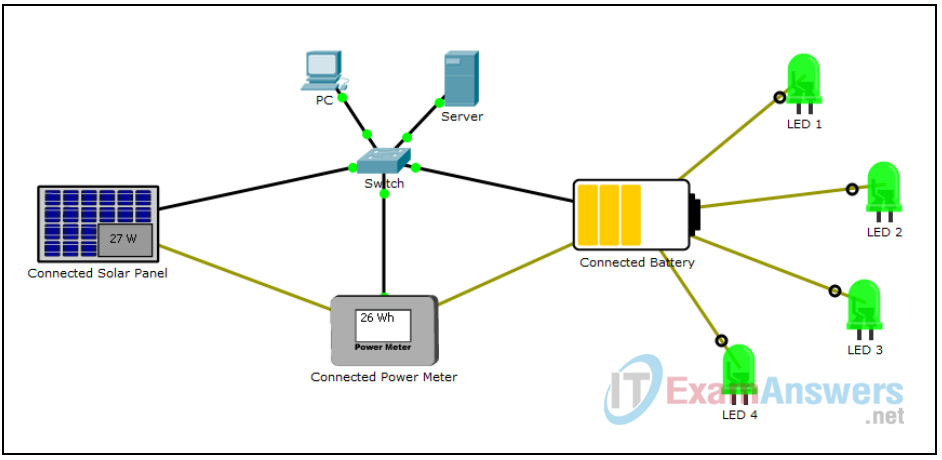
Topology
Objectives
Get familiar with using Packet Tracer 7.1 and its IoT connections.
Background / Scenario
In this activity you will build a connected solar-based power supply.
The sun charges the solar panel which sends electricity to the battery for power storage and distribution. A power meter connected between them reads and display the amount of power being captured by the solar panel.
Because all devices are connected (IoT capabilities), they register themselves with a registration server, allowing a user to monitor the entire system from a web browser (running in the PC).
Required Resources
- Packet Tracer 7.1 or newer.
Part 1: Adding and Connecting the Necessary Devices
You will start with four LEDs, a PC, a switch and a server. Add the following devices by locating and dragging them to Packet Tracer’s work space:
Note: Light Emitting Diodes (LEDs) are electronic components used to emit light. LEDs are widely used in electronics as a form of user interaction.
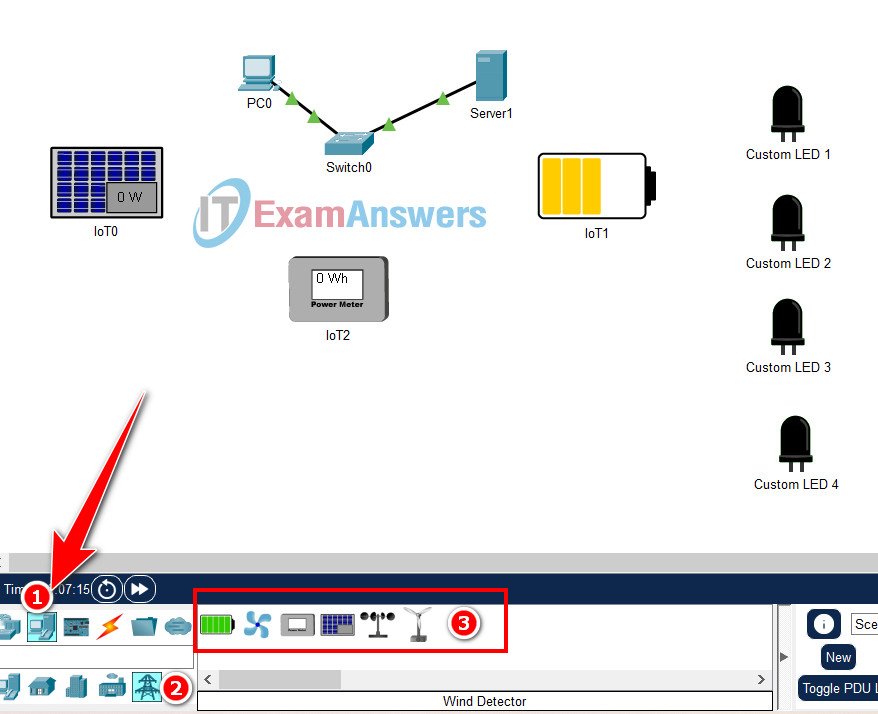
End Devices >> Power Grid
a. A PT-Solar Panel device. PT-Solar Panel can be found under End Devices >> Power Grid.
b. A PT-Battery device. PT-Battery can be found under End Devices >> Power Grid.
c. A PT-Power Meter device. PT-Power Meter can be found under End Devices >> Power Grid.
d. Using IoT Custom Cables, connect the solar panel and the battery to the power meter according to the table below. The IoT Custom Cable can be found under Connections.
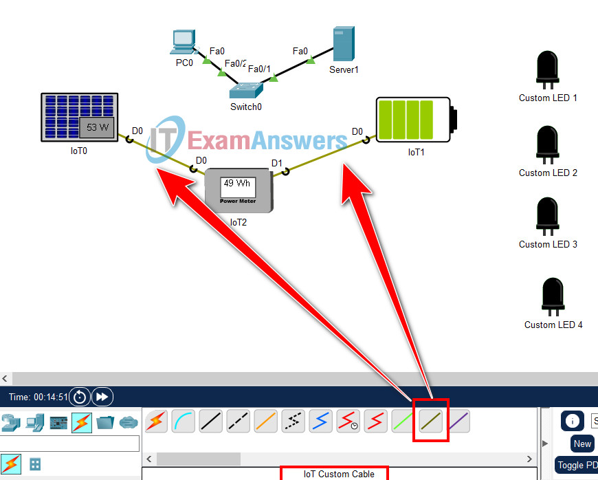
Using IoT Custom Cables
Use the table below to find the correct ports:
| Device | Port | Power Meter Port |
|---|---|---|
| Solar Panel | D0 | D0 |
| Battery | D0 | D1 |
e. Using IoT Custom Cables, connect the LEDs to the battery according to the table below. The IoT Custom Cable can be found under Connections.
Use the table below to find the correct ports:
| Device | Battery Port |
|---|---|
| LED1 | D1 |
| LED2 | D2 |
| LED3 | D3 |
| LED4 | D4 |
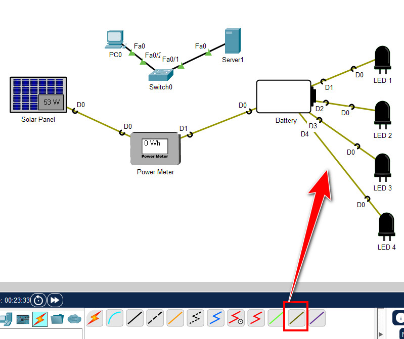
Note: Packet Tracer may name IoT devices differently. While the name will not impact the activity, feel free to rename your devices for easy identification.
Note: For simplicity, Packet Tracer does not implement power cable properly. Wiring and powering devices involve concepts such as ground, polarity, specific connectors, cable width and more. For simplicity, Packet Tracer hides all these variables behind the multi-use cable IoT Custom Cable. In real world designs, make sure to select the proper cable and connectors.
f. Using an Ethernet straight-through cable, connect the Ethernet port of the solar power, battery, and power meter to the switch according the table below. This is to ensure they can communicate with the Server. Ethernet straight-through cables can be found under Connections.
| Device | Switch Port |
|---|---|
| Solar Panel | Fa0/3 |
| Power Meter | Fa0/4 |
| Battery | Fa0/5 |
Part 2: Configuring The Devices
Now that the devices are properly cabled, they must be configured. Since this system relies on an IP network, the devices must be configured with correct IP information. Since the server is configured to also act as a DHCP server, the IoT devices should be configured as DHCP clients in order to learn IP information automatically.
a. Click the solar panel, navigate to the Config tab >> GigabitEthernet0 and select DHCP under IP Configuration.
b. Click the power meter, navigate to the Config tab >> FastEthernet0 and select DHCP under IP Configuration.
c. Click the battery, navigate to the Config tab >> FastEthernet0 and select DHCP under IP
Configuration.
What IP addresses were learned by the solar panel, power meter and battery?
Responses will vary due to dynamic DHCP assignment. The address must be on network 1.0.0.0/24. Possible addresses are 1.0.0.3, 1.0.0.4, 1.0.0.5.
d. Before the device can operate properly, they must register to the server. Configure the devices with the server’s IP address to allow them to find and communicate to the server.
Click the solar panel, navigate to the Config tab >> Settings and select Remote Server under IoT Server. Enter the following server information:
Server Address: 1.0.0.1
Username: admin
Password: admin
e. Click Connect.
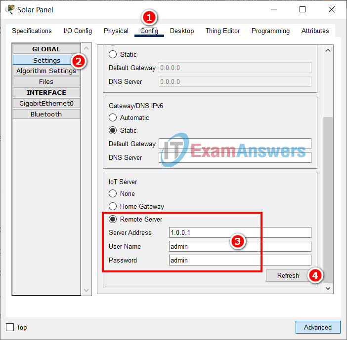
f. Repeat the process for the power meter and battery. Use the same server address, username, and password as shown above.
Part 3: Using the System
a. Now that all devices are connected, notice how the solar panel charges the battery.
b. Notice how the LEDs draw power from battery for operation.
c. Notice how the LEDs go dark if the battery has no charge.
d. Click the PC and navigate to Desktop >> Web Browser.
e. Type the IP address of the server, 1.0.0.1, and press enter.
f. Use the following credentials to log into the server:
Username: admin
Password: admin
How many devices are displayed in the page? What are their names?
Three. Solar panel connected, Battery connected and Power meter connected.
Why are the other devices, the Switch, the Server and the PC not listed? Is this a mistake?
These are network devices. No, it’s not a mistake. Network devices are only there to provide connectivity and should not be listed.
g. Click each device to expand it and monitor the status of a specific device.
Part 4: Reflection
The power of this IoT solution becomes clear when a user can monitor the power consumption of the system not only locally but also remotely. One step further would be to connect a microcontroller and write code to turn off one or more the LEDs when the battery power dropped below a pre-defined threshold. This energy saving mode would allow the battery some time to recharge before all the LEDs could be brought up again.

Great lab