2.1.1.5 Lab – The World Runs on Circuits (Instructor Version)
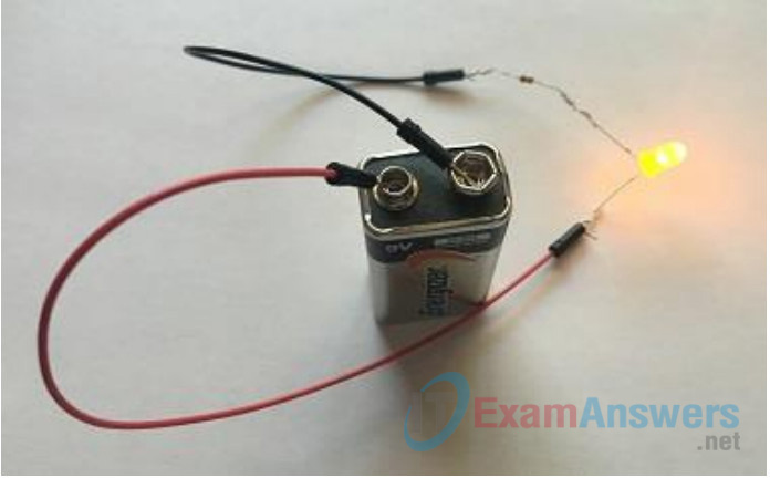
Topology

Objectives
- Part 1: Create a Simple Circuit using a 9V Battery as its Power Source
- Part 2: Create a Simple Circuit using a 1.5V Battery (AA or D Cell) as its Power Source
Background / Scenario
In this lab, you will build a simple circuit to illuminate a light-emitting diode (LED). This can be done by connecting a 9V battery to a couple wires, a 330 Ohm resistor and a LED. Next you will replace the 9V battery with a 1.5V AA or D cell battery and test your circuit.
Required Resources
- 1 – 9V Battery
- 1 – 1.5V AA or D Cell Battery
- 1 – 5mm LED
- 1 – 330 Ohm Resistor
- 2 – Jumper wires (1 rad wire, 1 black wire)
Part 1: Create a Simple Circuit using a 9V Battery as its Power Source
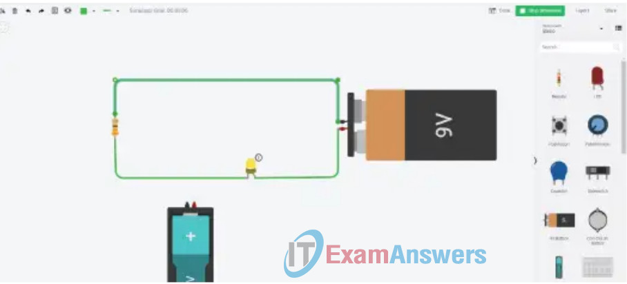
In Part 1 of this lab, you will build a simple circuit using a couple jumper wires, a 330 Ohm resistor, a 5mm LED, and a 9V battery as its power source.
Step 1: Connect the resistor to the negative leg of LED.
Each LED as two metal legs. Normally one leg is shorter than the other leg. The shorter leg is the negative side of the LED, called the Cathode. The positive leg is called the Anode.
Note: The glass ridge of the LED is normally flat on the Cathode side.
a. Twist the lead on one side of the resistor around the Cathode leg of the LED.
b. Twist the other lead of the resistor around one exposed end of the black jumper wire.
Step 2: Connect the red jumper wire to the positive leg of the LED.
Twist the Anode (positive) leg of the LED around the exposed end on one side of the red jumper wire.
Step 3: Connect the 9V battery to the remaining jumper wire ends.
a. Touch and hold the remaining unused end of the black jumper wire to negative side of the 9V battery, as shown in the Topology image.
b. Touch and hold the remaining unused end of the red jumper wire to the positive side of the 9V battery, as shown in the Topology image.
Note: Do not allow the red and black wires to touch each other. Directly connecting one pole of a battery to the other can create a fire orexplosion hazard.

Did the LED turn on? Yes
If the LED did not turn on, then verify that the circuit was connected correctly. If the wrong side of the LED was connected to the resistor, the LED will not turn on.
Why was the resistor needed for this circuit?
A 9V battery provides more current than the LED can handle, which can cause the LED to fail.
Part 2: Create a Simple Circuit using a 1.5V Battery as its Power Source
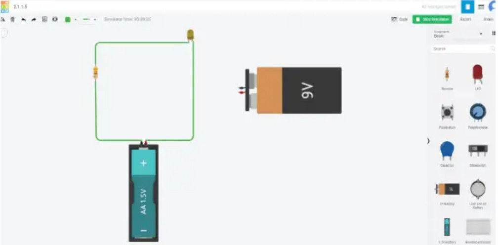
Step 1: Remove the 9V battery from the circuit that you built in Part 1. .
Step 2: Connect the 1.5V battery to the remaining jumper wire ends.
a. Attach the unused end of the black jumper wire to the negative side of the 1.5V battery.
b. Attach the unused end of the red jumper wire to the positive side of the 1.5V battery.

Did the LED turn on? No
If No, why didn’t the LED turn on?
A single 1.5V battery does not provide enough current to power the LED. A 5mm LED requires about 2V to light up.
Reflection
1. Is it possible to use multiple AA or D batteries to light a LED?
Yes. Multiple 1.5V batteries in series are used to power most flashlights.
2. How many 1.5V batteries would be needed to illuminate a 5mm LED?
Two 1.5V batteries. Connecting 2 1.5V batteries in series should provide approximately 3V, enough to power a 5mm LED.
