2.2.3.2 Lab – Photo Resistor using Redboard and Arduino IDE (Instructor Version)
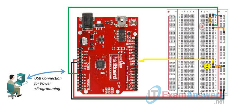
Topology
Objectives
- Configure the Photo Resistor circuit
- Load and run the sketch in the Arduino IDE
- Modify the sketch to adjust the light range
- Convert the sketch to make the circuit work as a night light
Background / Scenario
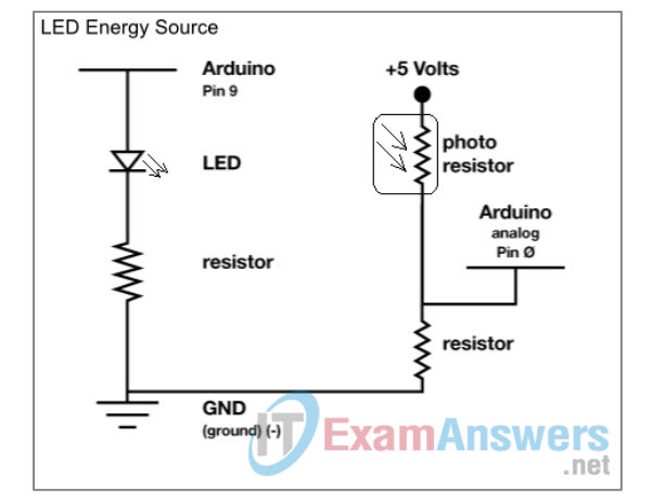
This lab will make use of a photo resistor to vary the voltage supplied to an LED based on the value read from the photo resistor. The pins that are used on the RedBoard are noted on the diagram, Pin 9 is used to vary the voltage to the LED which changes the brightness. Pin 9 is capable of simulating analog output using Pulse Wave Modulation (PWM).
Required Resources
- SparkFun Inventors Kit or equivalent components
- PC configured with Arduino drivers and Arduino software
- SIK Guide Code example files
Step 1: Configure the Photo Resistor circuit.
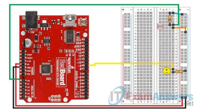
a. Select 1 – 330 Ohm (Ω) resistor, 1 – 10K Ohm (Ω) resistor, 1 red wire, 1 black wire, 1 green wire, 1 blue wire, 1 orange wire, 1 yellow wire, 1 LED and the photo resistor from the SIK.
b. Insert the 10K Ohm (Ω) resistor onto the breadboard; connecting it to i1 and i5.
Note: It does not matter which direction the resister is inserted.
c. Insert the 330 Ohm (Ω) resistor onto the breadboard; connecting it to j21 and the (-) bar on the right side of the breadboard.
d. Insert the LED making certain that the longest leg (anode) of the LED is inserted in h20 on the breadboard. The shorter leg (cathode) is inserted in h21.
Note: The LED will not work if the legs are reversed. If both legs are the same length, then the LED will have a flat edge on the cathode side.
e. Insert the photo resistor into f5 and f6.
Note: It does not matter which direction the photo resister is inserted.
f. Connect the blue wire from j1 to the (-) bar.
g. Connect the green wire from j5 on the breadboard to Pin A0 on the RedBoard.
h. Connect the orange wire from j6 to a (+) socket near j6.
i. Connect the yellow wire from j20 on the breadboard to Pin 9 on the RedBoard.
j. Connect the black wire from the breadboard ground (-) to the GND on the RedBoard.
k. Connect the red wire from the breadboard positive (+) to the 5V pin on the RedBoard.
Step 2: Load and run the sketch in the Arduino IDE.
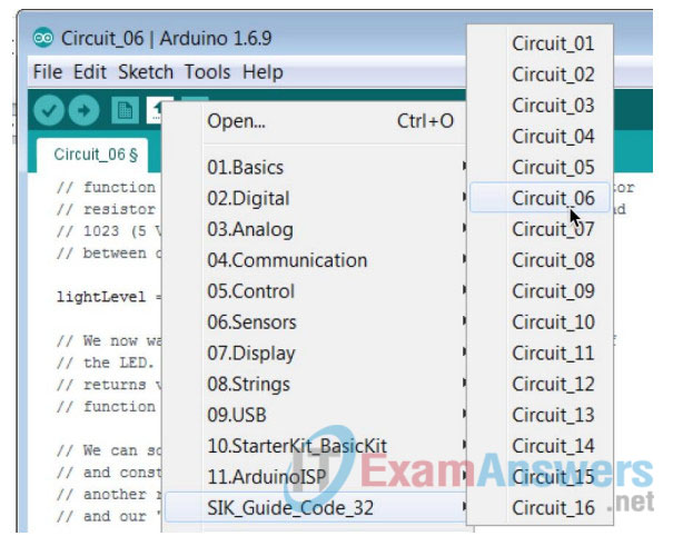
a. The Arduino IDE has shortcut buttons directly below the Menu bar. The icon with an up arrow provides a shortcut to the example sketch available. Click the up arrow and select Circuit_06 from the SIK_Guide_Code_32 folder displayed.
Note: The SIK_Guide_Code_32 folder will only exist if the code has been downloaded from http://sparkfun.com/sikcode and copied to the examples folder located under the Arduino program files, typically C:\Program Files\Arduino\examples.
b. Verify and compile the sketch by clicking the Checkmark in the shortcut bar. This creates an executable firmware that can be uploaded to the Flash memory of the microcontroller.
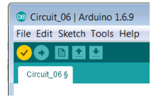
c. Make sure the RedBoard is connected to the PC with the USB cable. Upload the firmware to the RedBoard by clicking the Right Arrow in the shortcut bar.
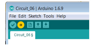
Note: The LED should light up when the sketch is delivered. The brightness will vary somewhat depending on the lighting conditions in the room.
d. Reduce the amount of light to the photo resistor. One suggestion is to carefully place something like a marker cap down over the photo sensor. The light should dim, it is unlikely to go completely off.
Step 3: Convert the sketch to make the circuit work as a night light.
a. Locate the line of code that reads:
analogWrite(ledPin, lightLevel);
b. Change the line to read:
analogWrite(ledPin, 255-lightLevel);
c. Recompile the sketch again by clicking the Checkmark in the shortcut bar.
d. Upload the new firmware by clicking the Right Arrow in the shortcut bar.
Note: Light levels range from 0 – 255. By subtracting the amount of light read from 255 when it is dark the light level read is 0, therefore the level being written will be 255 or bright light. When there is a lot of light in a room the light will be dim or possibly even off. Try shining a flashlight on the photo resistor to cause the light to go out.
Reflection
If you disconnected the Arduino USB cable from your PC and then reconnected it, would you need to upload the sketch to the Arduino RedBoard? Explain.
No, the firmware stays on the RedBoard until it is replaced by new firmware.
