3.2.6.6 Lab – Control LEDs from the PL-App Dashboard (Instructor Version)
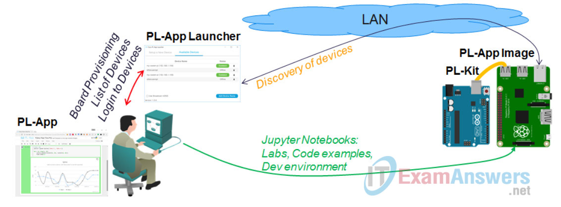
Topology

Objectives
- Build the Prototype Circuit
- Using PL-App with Raspberry Pi and Arduino
Background / Scenario
PL-App provides an web based interactive notebook interface, which can contain not only relatime graphs to visualize measured data in form of a chart, but also interactive widgets that can provide control using interactive checkboxes and sliders. The interactive widgets can be used to turn on or off, or change the behavior of components connected to the Raspberry Pi or Arduino.
In this lab, the interactive PL-App notebook with interactive widgets will be used to control the LEDs connected to the GPIO pins of an Arduino. The PWM (Pulse Wave Modulation) signal will be used to dim the LEDs.
Required Resources
- PC with Internet Access
- Ethernet based connection to the Internet with DHCP and no traffic filtering
- Raspberry Pi that is configured and imaged for PL-App access
- RedBoard or compatible
- Breadboard, resistors, LEDs, wires
Part 1: Build the Prototype Circuit

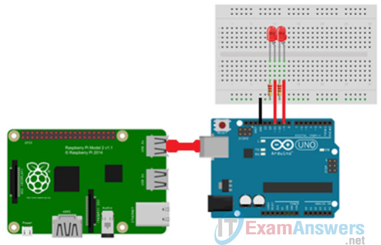
Step 1: Add two LEDs to an Arduino board
Using the PL-App notebook interactive widgets, a checkbox and a slider widget will control two LEDs connected to an Arduino board. The interactive widget checkbox widget will simply turn on or off the first LED, while the slider widget will dim the light of the second LED.
1. Select 2 – 330 Ohm (Ω) resistor, 2 LEDs, 2 red jumper wire, 1 black jumper wire from the Raspberry Pi starter kit.
2. Insert the first LED onto the breadboard. The cathode leg is connected to e10 and the anode leg is to be connected to e11.
3. Insert the second LED onto the breadboard. The cathode leg is connected to e12 and the anode leg is to be connected to e13.
4. Insert the first resistor onto the breadboard into the a10 and the negative (-) connector closes to the a row.
5. Insert the second resistor onto the breadboard into the a12 and the negative (-) connector closes to the a row.
6. Connect one end of the Black jumper wire to the negative (-) connector closes to the a row. Connect the other end of the Black jumper wire to one of the GND pins on the RedBoard.
7. Connect one end of the first Red jumper wire to a11 on the breadboard and the other end to pin 11 on the RedBoard.
8. Connect one end of the second Red jumper wire to a13 on the breadboard and the other end to pin 9 on the RedBoard.
Note: The ~ sign next to the pin number on the Arduino board identifies a PWM capable pin. Since at least the second LED should be dimmed, it must be connected to a PWM capable pin.
Step 2: Connect the Arduino with the Raspberry Pi
Using a USB cable that came with the SIK, connect the Arduino to the Raspberry Pi. The USB cable between the Arduino and the Raspberry Pi is not only used to power the Arduino, but it also provides a serial communication channel to control and monitor the Arduino from applications running on the Raspberry Pi.
Part 2: Using PL-App noteboook with iPython Interactive Widgets
Step 1: Simple use of iPython Interactive Widgets
The PL-App notebook can be extended using the so called iPython Interfactive Widgets. These objects provide visual objects (sliderx, checkboxex, etc.) that enable control of the application that is prototyped inside of the notebook.
All the different ipywidgets are available in the ipywidgets python module. To use them, simply import the module to the Python code (import ipywidgets).
A good practice is to import only the required functionality of different modules, therefore the example code below only imports the interact function from ipywidgets by using
from ipywidgets import interact
The interact function is expecting two parametets:
- The first is the function name to call when the interactive object is used by the user (e.g. clicked on checkbox, moved the slider, etc.)
- Type of interactive object to create. This can be a boolean to create checkbox interface, range to create a slider interface, etc.
To learn more about the ipywidges, check either this sample Chestnut notebook with additional examples or the official documentation.
Execute the cell below to play with the interact function of ipywidgets. Try to modify the variables, etc.
from ipywidgets import interact

def interactFunctionExample1(parameter):
    print(parameter)
def interactFunctionExample2(parameter):
    print(parameter)

interact(interactFunctionExample1, parameter=True)
interact(interactFunctionExample2, parameter=(0,255))
Part 3: Controlling LEDs using iPython Interactive Widgets
Step 1: Python with RedBoard (Arduino) using Firmata
Firmata is a serial communication protocol that enables control of the RedBoard (Arduino boards) over a serial interface, without the need to reflash the RedBoard every time with a new problem specific firmware.
If you have not already done so, flash the RedBoard with the Firmata firmware:
import chestnut.arduino
print 'Flashing Firmata to a RedBoard/Arduino connected as a USB serial device'
chestnut.arduino.flash_firmata("uno", '/dev/ttyUSB0)'

*where the "/dev/ttyUSB0" is the device name of the Arduino/RedBoard*
The controlling device, in this case the PL-App Raspberry Pi uses the RedBoard’s serial communication device to send a receive Firmata messages. These messages can be for example control commands which in a human language could be represented as: “Hi RedBoard, what is the current value of the Analog Input Pin 0?“, or “Hi RedBoard, turn on the GPIO pin 13“, etc.
To use the Firmata libraries in Python, import the “pyfirmata” module:
from pyfirmata import Arduino, util
and then connect to a RedBoard (Arduino) using the
board = Arduino(/dev/ttyUSB0)
command, where the /dev/ttyUSB0 is the name the RedBoard’s USB Serial Communication Device on Linux. If the connection is successfull, the connected RedBoard can be controlled directly from Python using statements such as:
# turn ON the GPIO PIN number 13
board.digital[13].write(True)

# turn OFF the GPIO PIN number 13
board.digital[13].write(False)
# Importing the required modules
from pyfirmata import Arduino, util

# Creating a connection to an Arduino/RedBoard from Python using Firmata
board = Arduino('/dev/ttyUSB0')

# Defining code variables that represent the actual GPIO PINs on the Arduino/RedBoard
ledOnOff = board.get_pin('d:9:o')
#                             ^ output
#                           ^ pin number
#                       ^ digital pins

ledDim   = board.get_pin('d:11:p')
#                             ^ pwm output
#                           ^ pin number
#                       ^ digital pins
Step 2: Interacting with the RedBoard from a notebook
Using the interact function of ipywidgets, the notebook provides interactive objects that can trigger function calls that modify the setting of a RedBoard:
# The functions to handle the interact requests
def interactFunctionTurnOnOffLed(ledOnOff_status):
    # get the global variable inside of this function
    global ledOnOff
    # use the value of the ledOnOff_status variable to set the state of the PIN represented as ledOnOff
    ledOnOff.write(ledOnOff_status)
    # print the current value for debug
    print(ledOnOff_status)
def interactFunctionDimLed(ledDim_value):
    # get the global variable inside of this function
    global ledDim
    # use the value of the ledDim_value variable to set the state of the PWM duty cycle on the PIN represented as ledDim
    #  the PWM value must be between 0.0 - 1.0 (therefore the ledDim_value is divided by 256.0)
    ledDim.write(ledDim_value/256.0)
    # print the current value for debug
    print(ledDim_value)

# Defining the interactive objects and their handling functions
#  checkbox with true or false state
interact(interactFunctionTurnOnOffLed, ledOnOff_status=True)
#  slider with values between 0 and 255
interact(interactFunctionDimLed, ledDim_value=(0,255))
Step 3: Challenge
Modify the code above so that you can turn on or off, as well as dim a single LED connected to a RedBoard/Arduino.
Reflection
Why is the code shown in three separate modules? What would happen if the code for the two widgets were joined to the top module?
