
2.4.11 Packet Tracer - Modify Single-Area OSPFv2 (Instructor Version)
Instructor Note: Red font color or green highlights indicate text that appears in the instructor copy only.
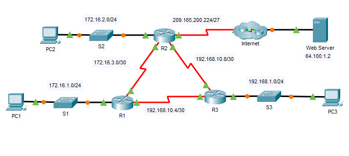
Addressing Table
| Device | Interface | IPv4 Address | Subnet Mask | Default Gateway |
|---|---|---|---|---|
| R1 | G0/0 | 172.16.1.1 | 255.255.255.0 | N/A |
| S0/0/0 | 172.16.3.1 | 255.255.255.252 | ||
| S0/0/1 | 192.168.10.5 | 255.255.255.252 | ||
| R2 | G0/0 | 172.16.2.1 | 255.255.255.0 | N/A |
| S0/0/0 | 172.16.3.2 | 255.255.255.252 | ||
| S0/0/1 | 192.168.10.9 | 255.255.255.252 | ||
| S0/1/0 | 209.165.200.225 | 255.255.255.224 | ||
| R3 | G0/0 | 192.168.1.1 | 255.255.255.0 | N/A |
| S0/0/0 | 192.168.10.6 | 255.255.255.252 | ||
| S0/0/1 | 192.168.10.10 | 255.255.255.252 | ||
| PC1 | NIC | 172.16.1.2 | 255.255.255.0 | 172.16.1.1 |
| PC2 | NIC | 172.16.2.2 | 255.255.255.0 | 172.16.2.1 |
| PC3 | NIC | 192.168.1.2 | 255.255.255.0 | 192.168.1.1 |
| Web Server | NIC | 64.100.1.2 | 255.255.255.0 | 64.100.1.1 |
Objectives
- Part 1: Modify OSPF Default Settings
- Part 2: Verify Connectivity
Scenario
In this activity, OSPF is already configured and all end devices currently have full connectivity. You will modify the default OSPF routing configurations by changing the hello and dead timers and adjusting the bandwidth of a link. Then you will verify that full connectivity is restored for all end devices.
Instructions
Part 1: Modify OSPF Default Settings
Step 1: Test connectivity between all end devices.
Before modifying the OSPF settings, verify that all PCs can ping the web server and each other.
Step 2: Adjust the hello and dead timers between R1 and R2.
a. Enter the following commands on R1.
R1(config)# interface s0/0/0
R1(config-if)# ip ospf hello-interval 15
R1(config-if)# ip ospf dead-interval 60
b. After a short period of time, the OSPF connection with R2 will fail, as shown in the router output.
00:02:40: %OSPF-5-ADJCHG: Process 1, Nbr 209.165.200.225 on Serial0/0/0 from FULL to DOWN, Neighbor Down: Dead timer expired

00:02:40: %OSPF-5-ADJCHG: Process 1, Nbr 209.165.200.225 on Serial0/0/0 from FULL to DOWN, Neighbor Down: Interface down or detached
Both sides of the connection need to have the same timer values in order for the adjacency to be maintained. Identify the interface on R2 that is connected to R1. Adjust the timers on the R2 interface to match the settings on R1.
R2(config)# interface s0/0/0
R2(config-if)# ip ospf hello-interval 15
R2(config-if)# ip ospf dead-interval 60
After a brief period of time you should see a status message that indicates that the OSPF adjacency has been reestablished.
00:21:52: %OSPF-5-ADJCHG: Process 1, Nbr 192.168.10.5 on Serial0/0/0 from LOADING to FULL, Loading Done
Step 3: Adjust the bandwidth setting on R1.
a. Trace the path between PC1 and the web server located at 64.100.1.2. Notice that the path from PC1 to 64.100.1.2 is routed through R2. OSPF prefers the lower cost path.
C:\> tracert 64.100.1.2

Tracing route to 64.100.1.2 over a maximum of 30 hops:

1 1 ms 0 ms 8 ms 172.16.1.1
2 0 ms 1 ms 0 ms 172.16.3.2
3 1 ms 9 ms 2 ms 209.165.200.226
4 * 1 ms 0 ms 64.100.1.2

Trace complete.
b. On the R1 Serial 0/0/0 interface, set the bandwidth to 64 Kb/s. This does not change the actual port speed, only the metric that the OSPF process on R1 will use to calculate best routes.
R1(config-if)# bandwidth 64
c. Trace the path between PC1 and the web server located at 64.100.1.2. Notice that the path from PC1 to 64.100.1.2 is redirected through R3. OSPF prefers the lower cost path.
C:\> tracert 64.100.1.2

Tracing route to 64.100.1.2 over a maximum of 30 hops:

1 1 ms 0 ms 3 ms 172.16.1.1
2 8 ms 1 ms 1 ms 192.168.10.6
3 2 ms 0 ms 2 ms 172.16.3.2
4 2 ms 3 ms 1 ms 209.165.200.226
5 2 ms 11 ms 11 ms 64.100.1.2

Trace complete.
Part 2: Verify Connectivity
Verify that all PCs can ping the web server and each other.
Device Configs - Final
Router R1
! ==============================================================
!--- 2.4.11 Packet Tracer - Modify Single-Area OSPFv2
!--- ANSWER SCRIPT FOR ROUTER R1
!--- Usage: from the console (or a Telnet/SSH session, if already reachable) on R1, enter privileged EXEC mode with "enable", then paste this whole file. Every line beginning with "!" is a comment; IOS ignores it, so pasting a comment by accident is harmless.
!--- OSPF is already fully configured and converged in this activity (process 1, all networks up). The only tasks are on the R1<->R2 link (S0/0/0): raise the hello/dead timers to match R2 (Part 1.2), then lower the bandwidth metric on that same interface so OSPF re-routes PC1's traffic to the web server via R3 instead of R2 (Part 1.3).
! ==============================================================

enable
configure terminal

! --------------------------------------------------------------
!--- Part 1, Step 2: Adjust the hello and dead timers toward R2
! --------------------------------------------------------------

!--- Both ends of an OSPF link must agree on hello/dead timers or the adjacency drops to DOWN (dead timer expired) - R2's S0/0/0 gets the same two values right after this.
interface Serial0/0/0
 ip ospf hello-interval 15
 ip ospf dead-interval 60

! --------------------------------------------------------------
!--- Part 1, Step 3: Adjust the bandwidth setting used for OSPF cost
! --------------------------------------------------------------

!--- Cosmetic to OSPF cost only - does not change the interface's real clock/line rate. Lowering it below R1's other path (via R3) makes OSPF prefer R3 for R1 -> web server traffic.
 bandwidth 64

end

! ==============================================================
!--- Verification (from R1 and PC1):
!---   R1# show ip ospf neighbor         -> adjacency with R2 should read FULL again a short while after both sides match timers (briefly DOWN in between, expected per the lab)
!---   R1# show ip ospf interface s0/0/0 -> confirms Hello 15, Dead 60, and Cost recalculated from the new 64 Kb/s bandwidth
!---   PC1> tracert 64.100.1.2           -> path shifts from via R2 (172.16.3.2) to via R3 (192.168.10.6) once the bandwidth change takes effect
! ==============================================================
Router R2
! ==============================================================
!--- 2.4.11 Packet Tracer - Modify Single-Area OSPFv2
!--- ANSWER SCRIPT FOR ROUTER R2
!--- Usage: from the console (or a Telnet/SSH session, if already reachable) on R2, enter privileged EXEC mode with "enable", then paste this whole file. Every line beginning with "!" is a comment; IOS ignores it, so pasting a comment by accident is harmless.
!--- OSPF is already fully configured and converged in this activity (process 1, all networks up). The only task on R2 is matching R1's new hello/dead timers on the shared S0/0/0 link (Part 1.2) so the adjacency comes back up; R2's bandwidth is left untouched (only R1's is changed in this lab).
! ==============================================================

enable
configure terminal

! --------------------------------------------------------------
!--- Part 1, Step 2: Adjust the hello and dead timers to match R1
! --------------------------------------------------------------

!--- R1 already set 15/60 on its end of this link - both sides need identical values for the OSPF adjacency to stay FULL instead of dropping to DOWN on the dead timer.
interface Serial0/0/0
 ip ospf hello-interval 15
 ip ospf dead-interval 60

end

! ==============================================================
!--- Verification (from R2):
!---   R2# show ip ospf neighbor         -> adjacency with R1 (192.168.10.5, Nbr on Serial0/0/0) shows FULL again, log line "...from LOADING to FULL, Loading Done"
!---   R2# show ip ospf interface s0/0/0 -> confirms Hello 15, Dead 60
!---   From PCs: verify PC1, PC2, PC3, and the web server can all still ping each other after the timer change
! ==============================================================


