5.0. Introduction
5.0.1. Why should I take this module?
Welcome to ACLs for IPv4 Configuration!
In the gated community where your grandparents live, there are rules for who can enter and leave the premises. The guard will not raise the gate to let you in to the community until someone confirms that you are on an approved visitor list. Much like the guard in the gated community, network traffic passing through an interface configured with an access control list (ACL) has permitted and denied traffic. How do you configure these ACLs? How do you modify them if they are not working correctly or if they require other changes? How do ACLs provide secure remote administrative access? Get started with this module to learn more!
5.0.2. What will I learn to do in this module?
Module Title: ACLs for IPv4 Configuration
Module Objective: Implement IPv4 ACLs to filter traffic and secure administrative access.
| Topic Title | Topic Objective |
|---|---|
| Configure Standard IPv4 ACLs | Configure standard IPv4 ACLs to filter traffic to meet networking requirements. |
| Modify IPv4 ACLs | Use sequence numbers to edit existing standard IPv4 ACLs. |
| Secure VTY Ports with a Standard IPv4 ACL | Configure a standard ACL to secure VTY access. |
| Configure Extended IPv4 ACLs | Configure extended IPv4 ACLs to filter traffic according to networking requirements. |
5.1. Configure Standard IPv4 ACLs
5.1.1. Create an ACL
In a previous module, you learned about what an ACL does and why it is important. In this topic, you will learn about creating ACLs.
All access control lists (ACLs) must be planned. However, this is especially true for ACLs requiring multiple access control entries (ACEs).
When configuring a complex ACL, it is suggested that you:
- Use a text editor and write out the specifics of the policy to be implemented.
- Add the IOS configuration commands to accomplish those tasks.
- Include remarks to document the ACL.
- Copy and paste the commands onto the device.
- Always thoroughly test an ACL to ensure that it correctly applies the desired policy.
These recommendations enable you to create the ACL thoughtfully without impacting the traffic on the network.
5.1.2. Numbered Standard IPv4 ACL Syntax
To create a numbered standard ACL, use the following global configuration command:
Router(config)# access-list access-list-number {deny | permit | remark text} source [source-wildcard] [log]
Use the no access-list access-list-number global configuration command to remove a numbered standard ACL.
The table provides a detailed explanation of the syntax for a standard ACL.
| Parameter | Description |
|---|---|
| access-list-number |
|
| deny | This denies access if the condition is matched. |
| permit | This permits access if the condition is matched. |
| remark text |
|
| source |
|
| source-wildcard | (Optional) This is a 32-bit wildcard mask that is applied to the source. If omitted, a default 0.0.0.0 mask is assumed. |
| log |
|
5.1.3. Named Standard IPv4 ACL Syntax
Naming an ACL makes it easier to understand its function. To create a named standard ACL, use the following global configuration command:
Router(config)# ip access-list standard access-list-name
This command enters the named standard configuration mode where you configure the ACL ACEs.
ACL names are alphanumeric, case sensitive, and must be unique. Capitalizing ACL names is not required but makes them stand out when viewing the running-config output. It also makes it less likely that you will accidentally create two different ACLs with the same name but with different uses of capitalization.
Note: Use the no ip access-list standard access-list-name global configuration command to remove a named standard IPv4 ACL.
In the example, a named standard IPv4 ACL called NO-ACCESS is created. Notice that the prompt changes to named standard ACL configuration mode. ACE statements are entered in the named standard ACL sub configuration mode. Use the help facility to view all the named standard ACL ACE options.
The three highlighted options are configured similar to the numbered standard ACL. Unlike the numbered ACL method, there is no need to repeat the initial ip access-list command for each ACE.
R1(config)# ip access-list standard NO-ACCESS
R1(config-std-nacl)# ?
Standard Access List configuration commands:
  <1-2147483647>  Sequence Number
  default         Set a command to its defaults
  deny            Specify packets to reject
  exit            Exit from access-list configuration mode
  no              Negate a command or set its defaults
  permit          Specify packets to forward
  remark          Access list entry comment
R1(config-std-nacl)#
5.1.4. Apply a Standard IPv4 ACL
After a standard IPv4 ACL is configured, it must be linked to an interface or feature. The following command can be used to bind a numbered or named standard IPv4 ACL to an interface:
Router(config-if) # ip access-group {access-list-number | access-list-name} {in | out}
To remove an ACL from an interface, first enter the no ip access-group interface configuration command. However, the ACL will still be configured on the router. To remove the ACL from the router, use the no access-list global configuration command.
5.1.5. Numbered Standard IPv4 ACL Example
The topology in the figure will be used to demonstrate configuring and applying numbered and named standard IPv4 ACLs to an interface. This first example shows a numbered standard IPv4 ACL implementation.
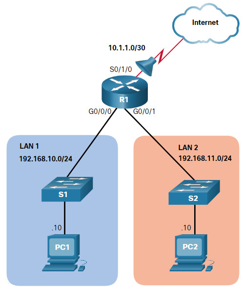
Assume only PC1 is allowed out to the internet. To enable this policy, a standard ACL ACE could be applied outbound on S0/1/0, as shown in the figure.
R1(config)# access-list 10 remark ACE permits ONLY host 192.168.10.10 to the internet
R1(config)# access-list 10 permit host 192.168.10.10
R1(config)# do show access-lists
Standard IP access list 10
    10 permit 192.168.10.10
R1(config)#
Notice that the output of the show access-lists command does not display the remark statements. ACL remarks are displayed in the running configuration file. Although the remark command is not required to enable the ACL, it is strongly suggested for documentation purposes.
Now assume that a new network policy states that hosts in LAN 2 should also be permitted to the internet. To enable this policy, a second standard ACL ACE could be added to ACL 10, as shown in the output.
R1(config)# access-list 10 remark ACE permits all host in LAN 2
R1(config)# access-list 10 permit 192.168.20.0 0.0.0.255
R1(config)# do show access-lists
Standard IP access list 10
    10 permit 192.168.10.10
    20 permit 192.168.20.0, wildcard bits 0.0.0.255
R1(config)#
Apply ACL 10 outbound on the Serial 0/1/0 interface.
R1(config)# interface Serial 0/1/0
R1(config-if)# ip access-group 10 out
R1(config-if)# end
R1#
The resulting policy of ACL 10 will only permit host 192.168.10.10 and all host from LAN 2 to exit the Serial 0/1/0 interface. All other hosts in the 192.168.10.0 network will not be permitted to the internet.
Use the show running-config command to review the ACL in the configuration, as shown in the output.
R1# show run | section access-list
access-list 10 remark ACE permits host 192.168.10.10
access-list 10 permit 192.168.10.10
access-list 10 remark ACE permits all host in LAN 2
access-list 10 permit 192.168.20.0 0.0.0.255
R1#
Notice how the remarks statements are also displayed.
Finally, use the show ip interface command to verify if an interface has an ACL applied to it. In the example output, the output is specifically looking at the Serial 0/1/0 interface for lines that include “access list” text.
R1# show ip int Serial 0/1/0 | include access list
  Outgoing Common access list is not set
  Outgoing access list is 10
  Inbound Common access list is not set
  Inbound  access list is not set
R1#
5.1.6. Named Standard IPv4 ACL Example
This second example shows a named standard IPv4 ACL implementation. The topology is repeated in the figure for your convenience.

Assume only PC1 is allowed out to the internet. To enable this policy, a named standard ACL called PERMIT-ACCESS could be applied outbound on S0/1/0.
Remove the previously configured named ACL 10 and create a named standard ACL called PERMIT-ACCESS, as shown here.
R1(config)# no access-list 10
R1(config)# ip access-list standard PERMIT-ACCESS
R1(config-std-nacl)# remark ACE permits host 192.168.10.10
R1(config-std-nacl)# permit host 192.168.10.10
R1(config-std-nacl)#
Now add an ACE permitting only host 192.168.10.10 and another ACE permitting all LAN 2 hosts to the internet.
R1(config-std-nacl)# remark ACE permits host 192.168.10.10
R1(config-std-nacl)# permit host 192.168.10.10
R1(config-std-nacl)# remark ACE permits all hosts in LAN 2
R1(config-std-nacl)# permit 192.168.20.0 0.0.0.255
R1(config-std-nacl)# exit
R1(config)#
Apply the new named ACL outbound to the Serial 0/1/0 interface.
R1(config)# interface Serial 0/1/0
R1(config-if)# ip access-group PERMIT-ACCESS out
R1(config-if)# end
R1#
Use the show access-lists and show running-config command to review the ACL in the configuration, as shown in the output.
R1# show access-lists
Standard IP access list PERMIT-ACCESS
    10 permit 192.168.10.10
    20 permit 192.168.20.0, wildcard bits 0.0.0.255
R1# show run | section ip access-list
ip access-list standard PERMIT-ACCESS
 remark ACE permits host 192.168.10.10
 permit 192.168.10.10
 remark ACE permits all hosts in LAN 2
 permit 192.168.20.0 0.0.0.255
R1#
Finally, use the show ip interface command to verify if an interface has an ACL applied to it. In the example output, the output is specifically looking at the Serial 0/1/0 interface for lines that include “access list” text.
R1# show ip int Serial 0/1/0 | include access list
  Outgoing Common access list is not set
  Outgoing access list is PERMIT-ACCESS
  Inbound Common access list is not set
  Inbound  access list is not set
R1#
5.1.7. Syntax Check – Configure Standard IPv4 ACLs
Configure a numbered and named ACLs on R1.
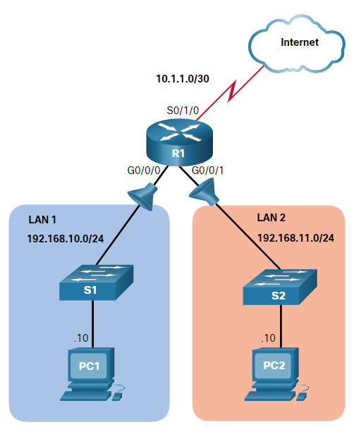
You will create a numbered ACL that denies host 192.168.10.10 but permits all other hosts in LAN 1. Start by configuring the ACL 20 ACE that denies the 192.168.10.10 host using the host keyword.

R1(config)#access-list 20 deny host 192.168.10.10

Create a second numbered ACL 20 ACE that permits all other hosts in LAN 1 on network 192.168.10.0/24.

R1(config)#access-list 20 permit 192.168.10.0 0.0.0.255

Because the ACL 20 policies only apply to traffic from the LAN 1, the ACL would be best applied incoming to the G0/0/0 R1 interface. Enter interface g0/0/0 mode, apply ACL 20 inbound, and return to global configuration mode. Be sure to use g0/0/0 as the interface designation.

R1(config)#interface g0/0/0
R1(config-if)#ip access-group 20 in
R1(config-if)#exit

You will now create a named standard ACL that permits host 192.168.10.10 but denies all other hosts access to LAN 2. Start by configuring a named standard ACL called LAN2-FILTER.

R1(config)#ip access-list standard LAN2-FILTER

Create an ACE that permits host 192.168.10.10 using the host keyword.

R1(config-std-nacl)#permit host 192.168.10.10

Deny all other hosts using the any keyword and return to global configuration mode.

R1(config-std-nacl)#deny any
R1(config-std-nacl)#exit

The LAN2-FILTER would be best applied outgoing to LAN 2. Enter interface g0/0/1 mode, apply ACL LAN2-FILTER outbound, and return to global configuration mode. Be sure to use g0/0/1 as the interface designation.

R1(config)#interface g0/0/1
R1(config-if)#ip access-group LAN2-FILTER out
R1(config-if)#exit

You have successfully configured IPv4 numbered and named standard ACLs on R1.
5.1.8. Packet Tracer – Configure Numbered Standard IPv4 ACLs
Standard access control lists (ACLs) are router configuration scripts that control whether a router permits or denies packets based on the source address. This activity focuses on defining filtering criteria, configuring standard ACLs, applying ACLs to router interfaces, and verifying and testing the ACL implementation. The routers are already configured, including IPv4 addresses and EIGRP routing.
5.1.8 Packet Tracer – Configure Numbered Standard IPv4 ACLs
5.1.9. Packet Tracer – Configure Named Standard IPv4 ACLs
The senior network administrator has asked you to create a named standard ACL to prevent access to a file server. All clients from one network and one specific workstation from a different network should be denied access.
5.1.9 Packet Tracer – Configure Named Standard IPv4 ACLs
5.2. Modify IPv4 ACLs
5.2.1. Two Methods to Modify an ACL
After an ACL is configured, it may need to be modified. ACLs with multiple ACEs can be complex to configure. Sometimes the configured ACE does not yield the expected behaviors. For these reasons, ACLs may initially require a bit of trial and error to achieve the desired filtering result.
This section will discuss two methods to use when modifying an ACL:
- Use a Text Editor
- Use Sequence Numbers
5.2.2. Text Editor Method
ACLs with multiple ACEs should be created in a text editor. This allows you to plan the required ACEs, create the ACL, and then paste it into the router interface. It also simplifies the tasks to edit and fix an ACL.
For example, assume ACL 1 was entered incorrectly using 19 instead of 192 for the first octet, as shown in the running configuration.
R1# show run | section access-list
access-list 1 deny   19.168.10.10
access-list 1 permit 192.168.10.0 0.0.0.255
R1#
In the example, the first ACE should have been to deny the host at 192.168.10.10. However, the ACE was incorrectly entered.
To correct the error:
- Copy the ACL from the running configuration and paste it into the text editor.
- Make the necessary edits changes.
- Remove the previously configured ACL on the router otherwise, pasting the edited ACL commands will only append (i.e., add) to the existing ACL ACEs on the router.
- Copy and paste the edited ACL back to the router.
Assume that ACL 1 has now been corrected. Therefore, the incorrect ACL must be deleted, and the corrected ACL 1 statements must be pasted in global configuration mode, as shown in the output.
R1(config)# no access-list 1
R1(config)#
R1(config)# access-list 1 deny 192.168.10.10
R1(config)# access-list 1 permit 192.168.10.0 0.0.0.255
R1(config)#
5.2.3. Sequence Numbers Method
An ACL ACE can also be deleted or added using the ACL sequence numbers. Sequence numbers are automatically assigned when an ACE is entered. These numbers are listed in the show access-lists command. The show running-config command does not display sequence numbers.
In the previous example, the incorrect ACE for ACL 1 is using sequence number 10, as shown in the example.
R1# show access-lists
Standard IP access list 1
    10 deny   19.168.10.10
    20 permit 192.168.10.0, wildcard bits 0.0.0.255
R1#
Use the ip access-list standard command to edit an ACL. Statements cannot be overwritten using the same sequence number as an existing statement. Therefore, the current statement must be deleted first with the no 10 command. Then the correct ACE can be added using sequence number 10 is configured. Verify the changes using the show access-lists command, as shown in the example.
R1# conf t
R1(config)# ip access-list standard 1
R1(config-std-nacl)# no 10
R1(config-std-nacl)# 10 deny host 192.168.10.10
R1(config-std-nacl)# end
R1# show access-lists
Standard IP access list 1
    10 deny   192.168.10.10
    20 permit 192.168.10.0, wildcard bits 0.0.0.255
R1#
5.2.4. Modify a Named ACL Example
Named ACLs can also use sequence numbers to delete and add ACEs. Refer to the example for ACL NO-ACCESS.
R1# show access-lists
Standard IP access list NO-ACCESS
    10 deny   192.168.10.10
    20 permit 192.168.10.0, wildcard bits 0.0.0.255
Assume that host 192.168.10.5 from the 192.168.10.0/24 network should also have been denied. If you entered a new ACE, it would be appended to the end of the ACL. Therefore, the host would never be denied because ACE 20 permits all hosts from that network.
The solution is to add an ACE denying host 192.168.10.5 in between ACE 10 and ACE 20, such as ACE 15, as shown in the example. Also notice that the new ACE was entered without using the host keyword. The keyword is optional when specifying a destination host.
Use the show access-lists command to verify the ACL now has a new ACE 15 inserted appropriately before the permit statement.
Notice that sequence number 15 is displayed prior to sequence number 10. We might expect the order of the statements in the output to reflect the order in which they were entered. However, the IOS puts host statements in an order using a special hashing function. The resulting order optimizes the search for a host ACL entry and then it searches for range statements.
Note: The hashing function is only applied to host statements in an IPv4 standard access list. The details of the hashing function are beyond the scope of this course.
R1# configure terminal
R1(config)# ip access-list standard NO-ACCESS
R1(config-std-nacl)# 15 deny 192.168.10.5
R1(config-std-nacl)# end
R1#
R1# show access-lists
Standard IP access list NO-ACCESS
    15 deny   192.168.10.5
    10 deny   192.168.10.10
    20 permit 192.168.10.0, wildcard bits 0.0.0.255
R1#
5.2.5. ACL Statistics
Notice that the show access-lists command in the example shows statistics for each statement that has been matched. The deny ACE in the NO-ACCESS ACL has been matched 20 times and the permit ACE has been matched 64 times.
Note that the implied deny any the last statement does not display any statistics. To track how many implicit denied packets have been matched, you must manually configure the deny any command at the end of the ACL.
Use the clear access-list counters command to clear the ACL statistics. This command can be used alone or with the number or name of a specific ACL.
R1# show access-lists
Standard IP access list NO-ACCESS
    10 deny   192.168.10.10  (20 matches)
    20 permit 192.168.10.0, wildcard bits 0.0.0.255  (64 matches)
R1# clear access-list counters NO-ACCESS
R1# show access-lists
Standard IP access list NO-ACCESS
    10 deny   192.168.10.10
    20 permit 192.168.10.0, wildcard bits 0.0.0.255
R1#
5.2.6. Syntax Checker – Modify IPv4 ACLs
Modify an ACL using sequence numbers.
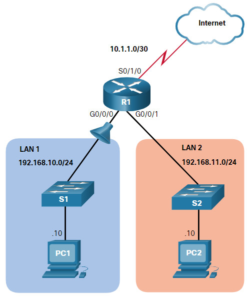
Use the show access-lists command to verify the configured ACLs.

R1#show access-lists
Standard IP access list 1
    10 deny   19.168.10.10
    20 permit 192.168.10.0, wildcard bits 0.0.0.255

You notice that ACE 10 is incorrect and needs to be edited. Enter global configuration mode and use the ip access-list standard command for ACL 1.

R1#configure terminal
R1(config)#ip access-list standard 1

An incorrect ACE must be deleted and then re-entered. Remove the ACE with sequence number 10.

R1(config-std-nacl)#no 10

Next, re-enter the correct ACE using sequence number 10 to deny the host with the IP address 192.168.10.10 access outside of LAN 1 and return to privileged EXEC mode using the end command.

R1(config-std-nacl)#10 deny host 192.168.10.10
R1(config-std-nacl)#end

Verify the new entry using the show access-lists command.

R1#show access-lists
Standard IP access list 1
    10 deny   192.168.10.10
    20 permit 192.168.10.0, wildcard bits 0.0.0.255

You have successfully modified an IPv4 numbered ACL on R1.
5.2.7. Packet Tracer – Configure and Modify Standard IPv4 ACLs
In this Packet Tracer activity, you will complete the following objectives:
- Part 1: Configure Devices and Verify Connectivity
- Part 2: Configure and Verify Standard Numbered and Named ACLs
- Part 3: Modify a Standard ACL
5.2.7 Packet Tracer – Configure and Modify Standard IPv4 ACLs
5.3. Secure VTY Ports with a Standard IPv4 ACL
5.3.1. The access-class Command
ACLs typically filter incoming or outgoing traffic on an interface. However, an ACL can also be used to secure remote administrative access to a device using the vty lines.
Use the following two steps to secure remote administrative access to the vty lines:
- Create an ACL to identify which administrative hosts should be allowed remote access.
- Apply the ACL to incoming traffic on the vty lines.
Use the following command to apply an ACL to the vty lines:
R1(config-line)# access-class {access-list-number | access-list-name} { in | out }
The in keyword is the most commonly used option to filter incoming vty traffic. The out parameter filters outgoing vty traffic and is rarely applied.
The following should be considered when configuring access lists on vty lines:
- Both named and numbered access lists can be applied to vty lines.
- Identical restrictions should be set on all the vty lines, because a user can attempt to connect to any of them.
5.3.2. Secure VTY Access Example
The topology in the figure is used to demonstrate how to configure an ACL to filter vty traffic. In this example, only PC1 will be allowed to Telnet in to R1.
Note: Telnet is used here for demonstration purposes only. SSH should be used in a production environment.
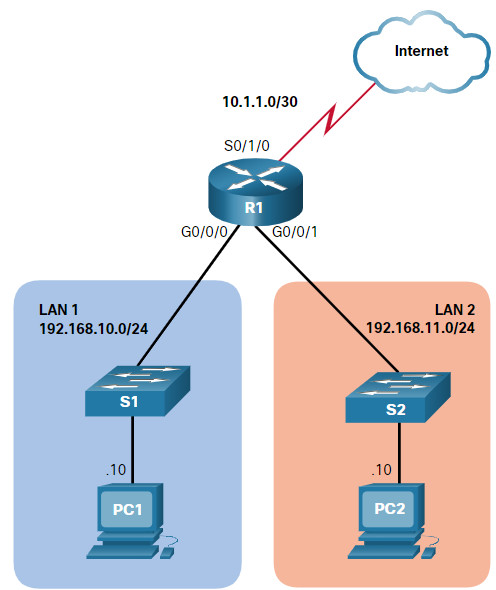
 To increase secure access, a username and password will be created, and the login local authentication method will be used on the vty lines. The command in the example creates a local database entry for a user ADMIN and password class.
A named standard ACL called ADMIN-HOST is created and identifies PC1. Notice that the deny any has been configured to track the number of times access has been denied.
The vty lines are configured to use the local database for authentication, permit Telnet traffic, and use the ADMIN-HOST ACL to restrict traffic.
R1(config)# username ADMIN secret class
R1(config)# ip access-list standard ADMIN-HOST
R1(config-std-nacl)# remark This ACL secures incoming vty lines
R1(config-std-nacl)# permit 192.168.10.10
R1(config-std-nacl)# deny any
R1(config-std-nacl)# exit
R1(config)# line vty 0 4
R1(config-line)# login local
R1(config-line)# transport input telnet
R1(config-line)# access-class ADMIN-HOST in
R1(config-line)# end
R1#
In a production environment, you would set the vty lines to only allow SSH, as shown in the example.
R1(config)# line vty 0 4
R1(config-line)# login local
R1(config-line)# transport input ssh
R1(config-line)# access-class ADMIN-HOST in
R1(config-line)# end
R1#
5.3.3. Verify the VTY Port is Secured
After the ACL to restrict access to the vty lines is configured, it is important to verify that it is working as expected.
As shown in the figure, when PC1 Telnets to R1, the host will be prompted for a username and password before successfully accessing the command prompt.
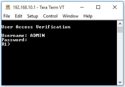
This verifies that PC1 can access R1 for administrative purposes.
Next, we test the connection from PC2. As shown in this figure, when PC2 attempts to Telnet, the connection is refused.
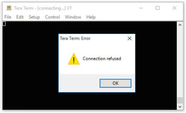
To verify the ACL statistics, issue the show access-lists command. Notice the informational message displayed on the console regarding the admin user. An informational console message is also generated when a user exits the vty line.
The match in the permit line of the output is a result of a successful Telnet connection by PC1. The match in the deny statement is due to the failed attempt to create a Telnet connection by PC2, a device on the 192.168.11.0/24 network.
R1#
Oct  9 15:11:19.544: %SEC_LOGIN-5-LOGIN_SUCCESS: Login Success [user: admin] [Source: 192.168.10.10] [localport: 23] at 15:11:19 UTC Wed Oct 9 2019
R1# show access-lists
Standard IP access list ADMIN-HOST
    10 permit 192.168.10.10  (2 matches)
    20 deny   any  (2 matches)
R1#
5.3.4. Syntax Checker – Secure the VTY Ports
Secure the vty lines for remote administrative access.

Create a local database entry for the name ADMIN and secret class.

R1(config)#username ADMIN secret class

Create a named standard ACL called ADMIN-HOST.

R1(config)#ip access-list standard ADMIN-HOST

Create a permit ACE for the host with IP address 192.168.10.10.

R1(config-std-nacl)#permit host 192.168.10.10

Next, add the implicit deny any and return to global configuration mode.

R1(config-std-nacl)#deny any
R1(config-std-nacl)#exit

Enter vty configuration mode to configure the five vty lines (i.e., 0 - 4).

R1(config)#line vty 0 4

Use the login local method for authentication and permit Telnet traffic.

R1(config-line)#login local
R1(config-line)#transport input telnet

Restrict inbound access to PC1 only using the access-class command and the named ACL ADMIN-HOST and return to privileged EXEC mode.

R1(config-line)#access-class ADMIN-HOST in
R1(config-line)#end

PC1 attempted to Telnet to R1 and was successful. PC2 attempted and was unsuccessful. Verify the ACL statistics to see if the ACLs are working as expected.

R1#show access-lists
Standard IP access list ADMIN-HOST
10 permit 192.168.10.10 (2 matches)
20 deny any (2 matches)

You have successfully modified an IPv4 numbered ACL on R1.
5.4. Configure Extended IPv4 ACLs
5.4.1. Extended ACLs
In the previous topics, you learned about how to configure and modify standard ACLs, and how to secure VTY ports with a standard IPv4 ACL. Standard ACLs only filter on source address. When more precise traffic-filtering control is required, extended IPv4 ACLs can be created.
Extended ACLs are used more often than standard ACLs because they provide a greater degree of control. They can filter on source address, destination address, protocol (i.e., IP, TCP, UDP, ICMP), and port number. This provides a greater range of criteria on which to base the ACL. For example, one extended ACL can allow email traffic from a network to a specific destination while denying file transfers and web browsing.
Like standard ACLs, extended ACLs can be created as:
- Numbered Extended ACL – Created using the access-list access-list-number global configuration command.
- Named Extended ACL – Created using the ip access-list extended access-list-name.
5.4.2. Numbered Extended IPv4 ACL Syntax
The procedural steps for configuring extended ACLs are the same as for standard ACLs. The extended ACL is first configured, and then it is activated on an interface. However, the command syntax and parameters are more complex to support the additional features provided by extended ACLs.
To create a numbered extended ACL, use the following global configuration command:
Router(config)# access-list access-list-number {deny | permit | remark text} protocol source source-wildcard [operator [port]] destination destination-wildcard [operator [port]] [established] [log]
Use the no ip access-list extended access-list-name global configuration command to remove an extended ACL.
Although there are many keywords and parameters for extended ACLs, it is not necessary to use all of them when configuring an extended ACL. The table provides a detailed explanation of the syntax for an extended ACL.
| Parameter | Description |
|---|---|
access-list-number |
|
deny |
This denies access if the condition is matched. |
permit |
This permits access if the condition is matched. |
remark text |
|
protocol |
|
source |
|
source-wildcard |
(Optional) A 32-bit wildcard mask that is applied to the source. |
destination |
|
destination-wildcard |
(Optional) This is a 32-bit wildcard mask that is applied to the destination. |
operator |
|
port |
(Optional) The decimal number or name of a TCP or UDP port. |
established |
|
log |
|
The command to apply an extended IPv4 ACL to an interface is the same as the command used for standard IPv4 ACLs.
Router(config-if) # ip access-group {access-list-number | access-list-name} {in | out}
To remove an ACL from an interface, first enter the no ip access-group interface configuration command. To remove the ACL from the router, use the no access-list global configuration command.
Note: The internal logic applied to the ordering of standard ACL statements does not apply to extended ACLs. The order in which the statements are entered during configuration is the order they are displayed and processed.
5.4.3. Protocols and Ports
Extended ACLs can filter on many different types of internet protocols and ports. Click each button for more information about the internet protocols and ports on which extended ACLs can filter.
5.4.4. Protocols and Port Numbers Configuration Examples
Extended ACLs can filter on different port number and port name options. This example configures an extended ACL 100 to filter HTTP traffic. The first ACE uses the www port name. The second ACE uses the port number 80. Both ACEs achieve exactly the same result.
R1(config)# access-list 100 permit tcp any any eq www
!or...
R1(config)# access-list 100 permit tcp any any eq 80
Configuring the port number is required when there is not a specific protocol name listed such as SSH (port number 22) or an HTTPS (port number 443), as shown in the next example.
R1(config)# access-list 100 permit tcp any any eq 22
R1(config)# access-list 100 permit tcp any any eq 443
R1(config)#
5.4.5. Apply a Numbered Extended IPv4 ACL
The topology in the figure will be used to demonstrate configuring and applying numbered and named extended IPv4 ACLs to an interface. This first example shows a numbered extended IPv4 ACL implementation.
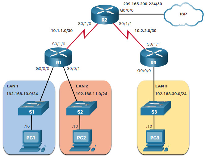
In this example, the ACL permits both HTTP and HTTPS traffic from the 192.168.10.0 network to go to any destination.
Extended ACLs can be applied in various locations. However, they are commonly applied close to the source. Therefore, ACL 110 was applied inbound on the R1 G0/0/0 interface.
R1(config)# access-list 110 permit tcp 192.168.10.0 0.0.0.255 any eq www
R1(config)# access-list 110 permit tcp 192.168.10.0 0.0.0.255 any eq 443
R1(config)# interface g0/0/0
R1(config-if)# ip access-group 110 in
R1(config-if)# exit
R1(config)#
5.4.6. TCP Established Extended ACL
TCP can also perform basic stateful firewall services using the TCP established keyword. The keyword enables inside traffic to exit the inside private network and permits the returning reply traffic to enter the inside private network, as shown in the figure.
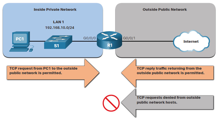
However, TCP traffic generated by an outside host and attempting to communicate with an inside host is denied.
The established keyword can be used to permit only the return HTTP traffic from requested websites, while denying all other traffic.
In the topology, the design for this example shows that ACL 110, which was previously configured, will filter traffic from the inside private network. ACL 120, using the established keyword, will filter traffic coming into the inside private network from the outside public network.

In the example, ACL 120 is configured to only permit returning web traffic to the inside hosts. The new ACL is then applied outbound on the R1 G0/0/0 interface. The show access-lists command displays both ACLs. Notice from the match statistics that inside hosts have been accessing the secure web resources from the internet.
R1(config)# access-list 120 permit tcp any 192.168.10.0 0.0.0.255 established
R1(config)# interface g0/0/0
R1(config-if)# ip access-group 120 out
R1(config-if)# end
R1# show access-lists
Extended IP access list 110
    10 permit tcp 192.168.10.0 0.0.0.255 any eq www
    20 permit tcp 192.168.10.0 0.0.0.255 any eq 443 (657 matches)
Extended IP access list 120
    10 permit tcp any 192.168.10.0 0.0.0.255 established (1166 matches)
R1#
Notice that the permit secure HTTPS counters (i.e., eq 443) in ACL 110 and the return established counters in ACL 120 have increased.
The established parameter allows only responses to traffic that originates from the 192.168.10.0/24 network to return to that network. Specifically, a match occurs if the returning TCP segment has the ACK or reset (RST) flag bits set. This indicates that the packet belongs to an existing connection. Without the established parameter in the ACL statement, clients could send traffic to a web server, but not receive traffic returning from the web server.
5.4.7. Named Extended IPv4 ACL Syntax
Naming an ACL makes it easier to understand its function. To create a named extended ACL, use the following global configuration command:
Router(config)# ip access-list extended access-list-name
This command enters the named extended configuration mode. Recall that ACL names are alphanumeric, case sensitive, and must be unique.
In the example, a named extended ACL called NO-FTP-ACCESS is created and the prompt changed to named extended ACL configuration mode. ACE statements are entered in the named extended ACL sub configuration mode.
R1(config)# ip access-list extended NO-FTP-ACCESS
R1(config-ext-nacl)#
5.4.8. Named Extended IPv4 ACL Example
Named extended ACLs are created in essentially the same way that named standard ACLs are created.
The topology in the figure is used to demonstrate configuring and applying two named extended IPv4 ACLs to an interface:
- SURFING – This will permit inside HTTP and HTTPS traffic to exit to the internet.
- BROWSING – This will only permit returning web traffic to the inside hosts while all other traffic exiting the R1 G0/0/0 interface is implicitly denied.

The example shows the configuration for the inbound SURFING ACL and the outbound BROWSING ACL.
The SURFING ACL permits HTTP and HTTPS traffic from inside users to exit the G0/0/1 interface connected to the internet. Web traffic returning from the internet is permitted back into the inside private network by the BROWSING ACL.
The SURFING ACL is applied inbound and the BROWSING ACL applied outbound on the R1 G0/0/0 interface, as shown in the output.
Inside hosts have been accessing the secure web resources from the internet. The show access-lists command is used to verify the ACL statistics. Notice that the permit secure HTTPS counters (i.e., eq 443) in the SURFING ACL and the return established counters in the BROWSING ACL have increased.
R1(config)# ip access-list extended SURFING
R1(config-ext-nacl)# Remark Permits inside HTTP and HTTPS traffic
R1(config-ext-nacl)# permit tcp 192.168.10.0 0.0.0.255 any eq 80
R1(config-ext-nacl)# permit tcp 192.168.10.0 0.0.0.255 any eq 443
R1(config-ext-nacl)# exit
R1(config)#
R1(config)# ip access-list extended BROWSING
R1(config-ext-nacl)# Remark Only permit returning HTTP and HTTPS traffic
R1(config-ext-nacl)# permit tcp any 192.168.10.0 0.0.0.255 established
R1(config-ext-nacl)# exit
R1(config)# interface g0/0/0
R1(config-if)# ip access-group SURFING in
R1(config-if)# ip access-group BROWSING out
R1(config-if)# end
R1# show access-lists
Extended IP access list SURFING
    10 permit tcp 192.168.10.0 0.0.0.255 any eq www
    20 permit tcp 192.168.10.0 0.0.0.255 any eq 443 (124 matches)
Extended IP access list BROWSING
    10 permit tcp any 192.168.10.0 0.0.0.255 established (369 matches)
R1#
5.4.9. Edit Extended ACLs
Like standard ACLs, an extended ACL can be edited using a text editor when many changes are required. Otherwise, if the edit applies to one or two ACEs, then sequence numbers can be used.
For example, assume you have just entered the SURFING and BROWSING ACLs and wish to verify their configuration using the show access-lists command.
R1# show access-lists
Extended IP access list BROWSING
    10 permit tcp any 192.168.10.0 0.0.0.255 established
Extended IP access list SURFING
    10 permit tcp 19.168.10.0 0.0.0.255 any eq www
    20 permit tcp 192.168.10.0 0.0.0.255 any eq 443
R1#
You notice that the ACE sequence number 10 in the SURFING ACL has an incorrect source IP networks address.
To correct this error using sequence numbers, the original statement is removed with the no sequence_# command and the corrected statement is added replacing the original statement.
R1# configure terminal
R1(config)# ip access-list extended SURFING
R1(config-ext-nacl)# no 10
R1(config-ext-nacl)# 10 permit tcp 192.168.10.0 0.0.0.255 any eq www
R1(config-ext-nacl)# end
The output verifies the configuration change using the show access-lists command.
R1# show access-lists
Extended IP access list BROWSING
    10 permit tcp any 192.168.10.0 0.0.0.255 established
Extended IP access list SURFING
    10 permit tcp 192.168.10.0 0.0.0.255 any eq www
    20 permit tcp 192.168.10.0 0.0.0.255 any eq 443
R1#
5.4.10. Another Named Extended IPv4 ACL Example
The figure shows another scenario for implementing a named extended IPv4 ACL. Assume that PC1 in the inside private network is permitted FTP, SSH, Telnet, DNS, HTTP, and HTTPS traffic. However, all other users in the inside private network should be denied access.
Two named extended ACLs will be created:
- PERMIT-PC1 – This will only permit PC1 TCP access to the internet and deny all other hosts in the private network.
- REPLY-PC1 – This will only permit specified returning TCP traffic to PC1 implicitly deny all other traffic.

The example shows the configuration for the inbound PERMIT-PC1 ACL and the outbound REPLY-PC1.
The PERMIT-PC1 ACL permits PC1 (i.e., 192.168.10.10) TCP access to the FTP (i.e., ports 20 and 21), SSH (22), Telnet (23), DNS (53), HTTP (80), and HTTPS (443) traffic.
The REPLY-PC1 ACL will permit return traffic to PC1.
There are many factors to consider when applying an ACL including:
- The device to apply it on
- The interface to apply it on
- The direction to apply it
Careful consideration must be taken to avoid undesired filtering results. The PERMIT-PC1 ACL is applied inbound and the REPLY-PC1 ACL applied outbound on the R1 G0/0/0 interface.
R1(config)# ip access-list extended PERMIT-PC1
R1(config-ext-nacl)# Remark Permit PC1 TCP access to internet
R1(config-ext-nacl)# permit tcp host 192.168.10.10 any eq 20
R1(config-ext-nacl)# permit tcp host 192.168.10.10 any eq 21
R1(config-ext-nacl)# permit tcp host 192.168.10.10 any eq 22
R1(config-ext-nacl)# permit tcp host 192.168.10.10 any eq 23
R1(config-ext-nacl)# permit tcp host 192.168.10.10 any eq 53
R1(config-ext-nacl)# permit tcp host 192.168.10.10 any eq 80
R1(config-ext-nacl)# permit tcp host 192.168.10.10 any eq 443
R1(config-ext-nacl)# deny ip 192.168.10.0 0.0.0.255 any
R1(config-ext-nacl)# exit
R1(config)#
R1(config)# ip access-list extended REPLY-PC1
R1(config-ext-nacl)# Remark Only permit returning traffic to PC1
R1(config-ext-nacl)# permit tcp any host 192.168.10.10 established
R1(config-ext-nacl)# exit
R1(config)# interface g0/0/0
R1(config-if)# ip access-group PERMIT-PC1 in
R1(config-if)# ip access-group REPLY-PC1 out
R1(config-if)# end
R1#
5.4.11. Verify Extended ACLs
After an ACL has been configured and applied to an interface, use Cisco IOS show commands to verify the configuration.
Click each button for more information about verifying the configuration of an ACL.
5.4.12. Packet Tracer – Configure Extended IPv4 ACLs – Scenario 1
In this Packet Tracer activity, you will complete the following objectives:
- Part 1: Configure, Apply, and Verify an Extended Numbered IPv4 ACL
- Part 2: Configure, Apply, and Verify an Extended Named IPv4 ACL
5.4.12 Packet Tracer – Configure Extended IPv4 ACLs – Scenario 1
5.4.13. Packet Tracer – Configure Extended IPv4 ACLs – Scenario 2
In this Packet Tracer activity, you will complete the following objectives:
- Part 1: Configure a Named Extended IPv4 ACL
- Part 2: Apply and Verify the Extended IPv4 ACL
5.4.13 Packet Tracer – Configure Extended IPv4 ACLs – Scenario 2
5.5. Module Practice and Quiz
5.5.1. Packet Tracer – IPv4 ACL Implementation Challenge
In this Packet Tracer challenge, you will configure extended, standard named, and extended named IPv4 ACLs to meet specified communication requirements.
5.5.1 Packet Tracer – IPv4 ACL Implementation Challenge
5.5.2. Lab – Configure and Verify Extended IPv4 ACLs
In this lab, you will complete the following objectives:
- Part 1: Build the Network and Configure Basic Device Settings
- Part 2: Configure and Verify Extended IPv4 ACLs
You can practice these skills using the Packet Tracer or lab equipment, if available.
Packet Tracer – Physical Mode (PTPM)
5.5.2 Packet Tracer – Configure and Verify Extended IPv4 ACLs – Physical Mode
Lab Equipment
5.5.2 Lab – Configure and Verify Extended IPv4 ACLs
5.5.3. What did I learn in this module?
Configure Standard IPv4 ACLs
All access control lists (ACLs) must be planned, especially for ACLs requiring multiple access control entries (ACEs). When configuring a complex ACL, it is suggested that you use a text editor and write out the specifics of the policy to be implemented, add the IOS configuration commands to accomplish those tasks, include remarks to document the ACL, copy and paste the commands on a lab device, and always thoroughly test an ACL to ensure that it correctly applies the desired policy. To create a numbered standard ACL, use the use the ip access-list standard access-list-name global configuration command. Use the no access-list access-list-number global configuration command to remove a numbered standard ACL. Use the show ip interface command to verify if an interface has an ACL applied to it. In addition to standard numbered ACLs, there are named standard ACLs. ACL names are alphanumeric, case sensitive, and must be unique. Capitalizing ACL names is not required but makes them stand out when viewing the running-config output. To create a named standard ACL, use the ip access-list standard access-list-name global configuration command. Use the no ip access-list standard access-list-name global configuration command to remove a named standard IPv4 ACL. After a standard IPv4 ACL is configured, it must be linked to an interface or feature. To bind a numbered or named standard IPv4 ACL to an interface, use the ip access-group {access-list-number | access-list-name} { in | out } global configuration command. To remove an ACL from an interface, first enter the no ip access-group interface configuration command. To remove the ACL from the router, use the no access-list global configuration command.
Modify IPv4 ACLs
To modify an ACL, use a text editor or use sequence numbers. ACLs with multiple ACEs should be created in a text editor. This allows you to plan the required ACEs, create the ACL, and then paste it into the router interface. An ACL ACE can also be deleted or added using the ACL sequence numbers. Sequence numbers are automatically assigned when an ACE is entered. These numbers are listed in the show access-lists command. The show running-config command does not display sequence numbers. Named ACLs can also use sequence numbers to delete and add ACEs. The show access-lists command shows statistics for each statement that has been matched. The clear access-list counters command to clear the ACL statistics.
Secure VTY Ports with a Standard IPv4 ACL
ACLs typically filter incoming or outgoing traffic on an interface. However, a standard ACL can also be used to secure remote administrative access to a device using the vty lines. The two steps to secure remote administrative access to the vty lines are to create an ACL to identify which administrative hosts should be allowed remote access and to apply the ACL to incoming traffic on the vty lines. The in keyword is the most commonly used option to filter incoming vty traffic. The out parameter filters outgoing vty traffic and is rarely applied. Both named and numbered access lists can be applied to vty lines. Identical restrictions should be set on all the vty lines, because a user can attempt to connect to any of them. After the ACL to restrict access to the vty lines is configured, it is important to verify that it is working as expected. Use the show ip interface command to verify if an interface has an ACL applied to it. To verify the ACL statistics, issue the show access-lists command.
Configure Extended IPv4 ACLs
Extended ACLs are used more often than standard ACLs because they provide a greater degree of control. They can filter on source address, destination address, protocol (i.e., IP, TCP, UDP, ICMP), and port number. This provides a greater range of criteria on which to base the ACL. Like standard ACLs, extended ACLs can be created as numbered extended ACL and named extended ACL. Numbered Extended ACLs are created using the same global configuration commands that are used for standard ACLs. The procedural steps for configuring extended ACLs are the same as for standard ACLs. However, the command syntax and parameters are more complex to support the additional features provided by extended ACLs. To create a numbered extended ACL, use the Router(config)# access-list access-list-number {deny | permit | remark text} protocol source source-wildcard [operator [port]] destination destination-wildcard [operator [port]] [established] [log] global configuration command. Extended ACLs can filter on many different types of internet protocols and ports. Selecting a protocol influences port options. For instance, selecting the tcp protocol would provide TCP related ports options. Configuring the port number is required when there is not a specific protocol name listed such as SSH (port number 22) or HTTPS (port number 443). TCP can also perform basic stateful firewall services using the TCP established keyword. The keyword enables inside traffic to exit the inside private network and permits the returning reply traffic to enter the inside private network. After an ACL has been configured and applied to an interface, use Cisco IOS show commands to verify the configuration. The show ip interface command is used to verify the ACL on the interface and the direction in which it was applied.

gg bylo super si to precitat ty kokot
Hello. Sorry if I’m wrong, I’m new here.
In 5.4.10, shouldn’t IN and OUT be reversed? Instead of:
R1(config-if)# ip access-group PERMIT-PC1 in
R1(config-if)# ip access-group REPLY-PC1 out
Shouldn’t it be:
R1(config-if)# ip access-group PERMIT-PC1 out
R1(config-if)# ip access-group REPLY-PC1 in
I think I figured it out. It seems IN means into the interface, and OUT means out of the interface. I thought IN means into the router, and OUT means of the router.