Lab - Configure VLANs and Trunking (Instructor Version)
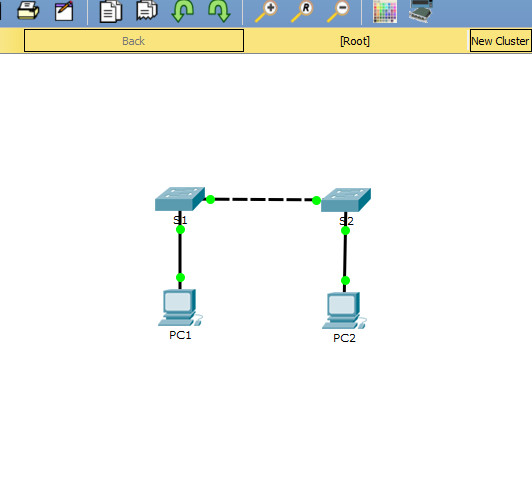
Topology

Addressing Table
| Device | Interface | IP Address | Subnet Mask |
|---|---|---|---|
| S1 | VLAN 1 | 192.168.1.11 | 255.255.255.0 |
| S2 | VLAN 1 | 192.168.1.12 | 255.255.255.0 |
| PC-A | NIC | 192.168.10.3 | 255.255.255.0 |
| PC-B | NIC | 192.168.10.4 | 255.255.255.0 |
Objectives
- Part 1: Build the Network and Configure Basic Device Settings
- Part 2: Create VLANs and Assign Switch Ports
- Part 3: Maintain VLAN Port Assignments and the VLAN Database
- Part 4: Configure an 802.1Q Trunk between the Switches
- Part 5: Delete the VLAN Database
Background / Scenario
Modern switches use virtual local-area networks (VLANs) to improve network performance by separating large Layer 2 broadcast domains into smaller ones. VLANs can also be used as a security measure by controlling which hosts can communicate. In general, VLANs make it easier to design a network to support the goals of an organization.
VLAN trunks are used to span VLANs across multiple devices. Trunks allow the traffic from multiple VLANS to travel over a single link, while keeping the VLAN identification and segmentation intact.
In this lab, you will create VLANs on both switches in the topology, assign VLANs to switch access ports, verify that VLANs are working as expected, and then create a VLAN trunk between the two switches to allow hosts in the same VLAN to communicate through the trunk, regardless of which switch the host is actually attached to.
Note: The switches used with CCNA hands-on labs are Cisco Catalyst 2960s with Cisco IOS Release 15.2(2) (lanbasek9 image). Other routers, switches, and Cisco IOS versions can be used. Depending on the model and Cisco IOS version, the commands available and the output produced might vary from what is shown in the labs. Refer to the Router Interface Summary Table at the end of the lab for the correct interface identifiers.
Note: Ensure that the routers and switches have been erased and have no startup configurations. If you are unsure contact your instructor.
Instructor Note: Refer to the Instructor Lab Manual for the procedures to initialize and reload devices.
Required Resources
- 2 Switches (Cisco 2960 with Cisco IOS Release 15.2(2) lanbasek9 image or comparable)
- 2 PCs (Windows with a terminal emulation program, such as Tera Term)
- Console cables to configure the Cisco IOS devices via the console ports
- Ethernet cables as shown in the topology
Instructions
Part 1: Build the Network and Configure Basic Device Settings
In Part 1, you will set up the network topology and configure basic settings on the PC hosts and switches.
Step 1: Cable the network as shown in the topology.
Attach the devices as shown in the topology diagram, and cable as necessary.
Step 2: Configure basic settings for each switch.
a. Console into the switch and enable privileged EXEC mode.
switch> enable
b. Enter configuration mode.
switch# config terminal
c. Assign a device name to the switch.
switch(config)# hostname S1

switch(config)# hostname S2
d. Disable DNS lookup to prevent the router from attempting to translate incorrectly entered commands as though they were host names.
S1(config)# no ip domain-lookup

S2(config)# no ip domain-lookup
e. Assign class as the privileged EXEC encrypted password.
S1(config)# enable secret class

S2(config)# enable secret class
f. Assign cisco as the console password and enable login.
S1(config)# line console 0
S1(config-line)# password cisco
S1(config-line)# login

S2(config)# line console 0
S2(config-line)# password cisco
S2(config-line)# login
g. Assign cisco as the vty password and enable login.
S1(config)# line vty 0 4
S1(config-line)# password cisco
S1(config-line)# login

S2(config)# line vty 0 4
S2(config-line)# password cisco
S2(config-line)# login
h. Encrypt the plaintext passwords.
S1(config)# service password-encryption

S2(config)# service password-encryption
i. Create a banner that warns anyone accessing the device that unauthorized access is prohibited.
S1(config)# banner motd $ Authorized Users Only! $

S2(config)# banner motd $ Authorized Users Only! $
j. Configure the IP address listed in the Addressing Table for VLAN 1 on the switch.
S1(config)# interface vlan 1
S1(config-if)# ip address 192.168.1.11 255.255.255.0
S1(config-if)# no shutdown
S1(config-if)# exit

S2(config)# interface vlan 1
S2(config-if)# ip address 192.168.1.12 255.255.255.0
S2(config-if)# no shutdown
S2(config-if)# exit
k. Shut down all interfaces that will not be used.
S1(config)# interface range f0/2-5, f0/7-24, g0/1-2
S1(config-if-range)# shutdown

S2(config)# interface range f0/2-17, f0/18-24, g0/1-2
S2(config-if-range)# shutdown
l. Set the clock on the switch.
S1# clock set 15:30:00 19 September 2019

S2# clock set 15:30:00 19 September 2019
m. Save the running configuration to the startup configuration file.
S1# copy running-config startup-config

S2# copy running-config startup-config
Step 3: Configure PC hosts.
Refer to the Addressing Table for PC host address information.
Step 4: Test connectivity.
Verify that the PC hosts can ping one another.
Note: It may be necessary to disable the PCs firewall to ping between PCs.
Can PC-A ping PC-B?
Yes
Can PC-A ping S1?
No
Can PC-B ping S2?
No
Can S1 ping S2?
Yes
If you answered no to any of the above questions, why were the pings unsuccessful?
Pings were unsuccessful when trying to ping a device on a different subnet. For those pings to be successful, a default gateway must exist to route traffic from one subnet to another.
Part 2: Create VLANs and Assign Switch Ports
In Part 2, you will create Management, Operations, Parking_Lot, and Native VLANs on both switches. You will then assign the VLANs to the appropriate interface. The show vlan command is used to verify your configuration settings.
Step 1: Create VLANs on the switches.
a. Create the VLANs on S1.
S1(config)# vlan 10
S1(config-vlan)# name Operations
S1(config-vlan)# vlan 20
S1(config-vlan)# name Parking_Lot
S1(config-vlan)# vlan 99
S1(config-vlan)# name Management
S1(config-vlan)# vlan 1000
S1(config-vlan)# name Native
S1(config-vlan)# end
b. Create the same VLANs on S2.
c. Issue the show vlan brief command to view the list of VLANs on S1.
S1# show vlan brief

VLAN Name                             Status    Ports
---- -------------------------------- --------- -------------------------------
1    default                          active    Fa0/1, Fa0/2, Fa0/3, Fa0/4
                                                Fa0/5, Fa0/6, Fa0/7, Fa0/8
                                                Fa0/9, Fa0/10, Fa0/11, Fa0/12
                                                Fa0/13, Fa0/14, Fa0/15, Fa0/16
                                                Fa0/17, Fa0/18, Fa0/19, Fa0/20
                                                Fa0/21, Fa0/22, Fa0/23, Fa0/24
                                                Gi0/1, Gi0/2
10   Operations                       active
20   Parking_Lot                      active
99   Management                       active
1000 Native                           active
1002 fddi-default                     act/unsup
1003 token-ring-default               act/unsup
1004 fddinet-default                  act/unsup
1005 trnet-default                    act/unsup
What is the default VLAN?
VLAN 1
What ports are assigned to the default VLAN?
All switch ports are assigned to VLAN 1 by default.
Step 2: Assign VLANs to the correct switch interfaces.
a. Assign VLANs to the interfaces on S1.
1) Assign PC-A to the Operation VLAN.
S1(config)# interface f0/6
S1(config-if)# switchport mode access
S1(config-if)# switchport access vlan 10
2) Move the switch IP address VLAN 99.
S1(config)# interface vlan 1
S1(config-if)# no ip address
S1(config-if)# interface vlan 99
S1(config-if)# ip address 192.168.1.11 255.255.255.0
S1(config-if)# end
b. Issue the show vlan brief command and verify that the VLANs are assigned to the correct interfaces.
S1# show vlan brief

VLAN Name                             Status    Ports
---- -------------------------------- --------- -------------------------------
1    default                          active    Fa0/1, Fa0/2, Fa0/3, Fa0/4
                                                Fa0/5, Fa0/7, Fa0/8, Fa0/9
                                                Fa0/10, Fa0/11, Fa0/12, Fa0/13
                                                Fa0/14, Fa0/15, Fa0/16, Fa0/17
                                                Fa0/18, Fa0/19, Fa0/20, Fa0/21
                                                Fa0/22, Fa0/23, Fa0/24, Gi0/1
                                                Gi0/2
10   Operations                       active    Fa0/6
20   Faculty                          active
99   Management                       active
1002 fddi-default                     act/unsup
1003 token-ring-default               act/unsup
1004 fddinet-default                  act/unsup
1005 trnet-default                    act/unsup
c. Issue the show ip interface brief command.
S1# show ip interface brief
Interface              IP-Address      OK? Method Status                Protocol
Vlan1                  unassigned      YES unset  up                    up
Vlan99                 192.168.1.11    YES manual up                    down
FastEthernet0/1        unassigned      YES unset  up                    up
FastEthernet0/2        unassigned      YES unset  administratively down down
FastEthernet0/3        unassigned      YES unset  administratively down down
FastEthernet0/4        unassigned      YES unset  administratively down down
FastEthernet0/5        unassigned      YES unset  administratively down down
FastEthernet0/6        unassigned      YES unset  up                    up
FastEthernet0/7        unassigned      YES unset  administratively down down
<output omitted>
What is the status of VLAN 99? Explain.
The status of VLAN 99 is up/down, up because the VLAN exists in the database but down because the VLAN has not been assigned to an active port yet.
d. Assign PC-B to the Operations VLAN on S2.
S2(config)# interface f0/18
S2(config-if)# switchport mode access
S2(config-if)# switchport access vlan 10
e. Remove the IP address for VLAN 1 on S2.
S2(config)# interface vlan 1
S2(config-if)# no ip address
f. Configure an IP address for VLAN 99 on S2 according to the Addressing Table.
S2(config-if)# interface vlan 99
S2(config-if)# ip address 192.168.1.12 255.255.255.0
g. Use the show vlan brief command to verify that the VLANs are assigned to the correct interfaces.
S2# show vlan brief

VLAN Name                             Status    Ports
---- -------------------------------- --------- -------------------------------
1    default                          active    Fa0/1, Fa0/2, Fa0/3, Fa0/4
                                                Fa0/5, Fa0/6, Fa0/7, Fa0/8
                                                Fa0/9, Fa0/10, Fa0/11, Fa0/12
                                                Fa0/13, Fa0/14, Fa0/15, Fa0/16
                                                Fa0/17, Fa0/19, Fa0/20, Fa0/21
                                                Fa0/22, Fa0/23, Fa0/24, Gi0/1
                                                Gi0/2
10   Operations                       active    Fa0/18
20   Parking_Lot                      active
99   Management                       active
1000 Native                           active
1002 fddi-default                     act/unsup
1003 token-ring-default               act/unsup
1004 fddinet-default                  act/unsup
1005 trnet-default                    act/unsup
Is S1 able to ping S2? Explain.
No. The IP addresses for the switches now reside in VLAN 99. VLAN 99 traffic will not be sent over interface F0/1.
Is PC-A able to ping PC-B? Explain.
No. Interface F0/1 is not assigned to VLAN 10, so VLAN 10 traffic will not be sent over it.
Part 3: Maintain VLAN Port Assignments and the VLAN Database
In Part 3, you will change VLAN assignments to ports and remove VLANs from the VLAN database.
Step 1: Assign a VLAN to multiple interfaces.
a. On S1, assign interfaces F0/11 – 24 to VLAN99.
S1(config)# interface range f0/11-24
S1(config-if-range)# switchport mode access
S1(config-if-range)# switchport access vlan 99
S1(config-if-range)# end
b. Issue the show vlan brief command to verify VLAN assignments.
S1# show vlan brief

VLAN Name                             Status    Ports
---- -------------------------------- --------- -------------------------------
1    default                          active    Fa0/1, Fa0/2, Fa0/3, Fa0/4
                                                Fa0/5, Fa0/7, Fa0/8, Fa0/9
                                                Fa0/10, Gi0/1, Gi0/2
10   Operations                       active    Fa0/6
20   Parking_Lot                      active
99   Management                       active    Fa0/11, Fa0/12, Fa0/13, Fa0/14
                                                Fa0/15, Fa0/16, Fa0/17, Fa0/18
                                                Fa0/19, Fa0/20, Fa0/21, Fa0/22
                                                Fa0/23, Fa0/24
1000 Native                           active
1002 fddi-default                     act/unsup
1003 token-ring-default               act/unsup
1004 fddinet-default                  act/unsup
1005 trnet-default                    act/unsup
c. Reassign F0/11 and F0/21 to VLAN 10.
S1(config)# interface range f0/11, f0/21
S1(config-if-range)# switchport access vlan 10
S1(config-if-range)# end
d. Verify that VLAN assignments are correct.
S1# show vlan brief

VLAN Name                             Status    Ports
---- -------------------------------- --------- -------------------------------
1    default                          active    Fa0/1, Fa0/2, Fa0/3, Fa0/4
                                                Fa0/5, Fa0/7, Fa0/8, Fa0/9
                                                Fa0/10, Gi0/1, Gi0/2
10   Operations                       active    Fa0/6, Fa0/11, Fa0/21
20   Parking_Lot                      active
99   Management                       active    Fa0/12, Fa0/13, Fa0/14, Fa0/15
                                                Fa0/16, Fa0/17, Fa0/18, Fa0/19
                                                Fa0/20, Fa0/22, Fa0/23, Fa0/24
1000 Native                           active
1002 fddi-default                     act/unsup
1003 token-ring-default               act/unsup
1004 fddinet-default                  act/unsup
1005 trnet-default                    act/unsup
Step 2: Remove a VLAN assignment from an interface.
a. Use the no switchport access vlan command to remove the VLAN 99 assignment to F0/24.
S1(config)# interface f0/24
S1(config-if)# no switchport access vlan
S1(config-if)# end
b. Verify that the VLAN change was made.
Which VLAN is F0/24 now associated with?
VLAN 1, the default VLAN.
S1# show vlan brief

VLAN Name                             Status    Ports
---- -------------------------------- --------- -------------------------------
1    default                          active    Fa0/1, Fa0/2, Fa0/3, Fa0/4
                                                Fa0/5, Fa0/7, Fa0/8, Fa0/9
                                                Fa0/10, Fa0/24, Gi0/1, Gi0/2
10   Operations                       active    Fa0/6, Fa0/11, Fa0/21
20   Parking_Lot                      active
99   Management                       active    Fa0/12, Fa0/13, Fa0/14, Fa0/15
                                                Fa0/16, Fa0/17, Fa0/18, Fa0/19
                                                Fa0/20, Fa0/22, Fa0/23
1000 Native                           active
1002 fddi-default                     act/unsup
1003 token-ring-default               act/unsup
1004 fddinet-default                  act/unsup
1005 trnet-default                    act/unsup
Step 3: Remove a VLAN ID from the VLAN database.
a. Add VLAN 30 to interface F0/24 without issuing the global VLAN command.
S1(config)# interface f0/24
S1(config-if)# switchport access vlan 30
% Access VLAN does not exist. Creating vlan 30
Note: Current switch technology no longer requires that the vlan command be issued to add a VLAN to the database. By assigning an unknown VLAN to a port, the VLAN will be created and added to the VLAN database.
b. Verify that the new VLAN is displayed in the VLAN table.
S1# show vlan brief

VLAN Name                             Status    Ports
---- -------------------------------- --------- -------------------------------
1    default                          active    Fa0/1, Fa0/2, Fa0/3, Fa0/4
                                                Fa0/5, Fa0/7, Fa0/8, Fa0/9
                                                Fa0/10, Gi0/1, Gi0/2
10   Operations                       active    Fa0/6, Fa0/11, Fa0/21
20   Parking_Lot                      active
30   VLAN0030                         active    Fa0/24
99   Management                       active    Fa0/12, Fa0/13, Fa0/14, Fa0/15
                                                Fa0/16, Fa0/17, Fa0/18, Fa0/19
                                                Fa0/20, Fa0/22, Fa0/23
1000 Native                           active
1002 fddi-default                     act/unsup
1003 token-ring-default               act/unsup
1004 fddinet-default                  act/unsup
1005 trnet-default                    act/unsup
What is the default name of VLAN 30?
VLAN0030
c. Use the no vlan 30 command to remove VLAN 30 from the VLAN database.
S1(config)# no vlan 30
S1(config)# end
d. Issue the show vlan brief command. F0/24 was assigned to VLAN 30.
After deleting VLAN 30 from the VLAN database, what VLAN is port F0/24 assigned to? What happens to the traffic destined to the host attached to F0/24?
When you delete a VLAN, any ports assigned to that VLAN become inactive. So Port F0/24 is still -associated to VLAN 30. However, VLAN 30 is now inactive because it does not exist in the VLAN database. Additionally, the port will not transfer any traffic.
S1# show vlan brief

VLAN Name                             Status    Ports
---- -------------------------------- --------- -------------------------------
1    default                          active    Fa0/1, Fa0/2, Fa0/3, Fa0/4
                                                Fa0/5, Fa0/7, Fa0/8, Fa0/9
                                                Fa0/10, Gi0/1, Gi0/2
10   Operations                       active    Fa0/6, Fa0/11, Fa0/21
20   Parking_Lot                      active
99   Management                       active    Fa0/12, Fa0/13, Fa0/14, Fa0/15
                                                Fa0/16, Fa0/17, Fa0/18, Fa0/19
                                                Fa0/20, Fa0/22, Fa0/23
1000 Native                           active
1002 fddi-default                     act/unsup
1003 token-ring-default               act/unsup
1004 fddinet-default                  act/unsup
1005 trnet-default                    act/unsup
e. Issue the no switchport access vlan command on interface F0/24.
S1(config)# interface f0/24
S1(config-if)# no switchport access vlan
S1(config-if)# end
f. Issue the show vlan brief command to determine the VLAN assignment for F0/24.
To which VLAN is F0/24 assigned?
The default VLAN, VLAN 1
S1# show vlan brief
VLAN Name                             Status    Ports
---- -------------------------------- --------- -------------------------------
1    default                          active    Fa0/1, Fa0/2, Fa0/3, Fa0/4
                                                Fa0/5, Fa0/7, Fa0/8, Fa0/9
                                                Fa0/10, Fa0/24, Gi0/1, Gi0/2
10   Operations                       active    Fa0/6, Fa0/11, Fa0/21
20   Parking_Lot                      active
99   Management                       active    Fa0/12, Fa0/13, Fa0/14, Fa0/15
                                                Fa0/16, Fa0/17, Fa0/18, Fa0/19
                                                Fa0/20, Fa0/22, Fa0/23
1000 Native                           active
1002 fddi-default                     act/unsup
1003 token-ring-default               act/unsup
1004 fddinet-default                  act/unsup
1005 trnet-default                    act/unsup
Note: Before removing a VLAN from the database, it is recommended that you reassign all the ports assigned to that VLAN.
Why should you reassign a port to another VLAN before removing the VLAN from the VLAN database?
The interfaces assigned to a VLAN that is the removed from the VLAN database become inactive and are unavailable for use until they are reassigned to another VLAN. This can be a tricky thing to troubleshoot as trunked interfaces do not show up in the port list as well (Part 4 contains more information about trunked interfaces).
Part 4: Configure an 802.1Q Trunk Between the Switches
In Part 4, you will configure interface F0/1 to use the Dynamic Trunking Protocol (DTP) to allow it to negotiate the trunk mode. After this has been accomplished and verified, you will disable DTP on interface F0/1 and manually configure it as a trunk.
Step 1: Use DTP to initiate trunking on F0/1.
The default DTP mode of a 2960 switch port is dynamic auto. This allows the interface to convert the link to a trunk if the neighboring interface is set to trunk or dynamic desirable mode.
a. Set F0/1 on S1 to negotiate trunk mode.
S1(config)# interface f0/1
S1(config-if)# switchport mode dynamic desirable
Sep 19 02:51:47.257: %LINEPROTO-5-UPDOWN: Line protocol on Interface FastEthernet0/1, changed state to up
Sep 19 02:51:47.291: %LINEPROTO-5-UPDOWN: Line protocol on Interface Vlan99, changed state to up
You should also receive link status messages on S2.
S2#
Sep 19 02:42:19.424: %LINK-3-UPDOWN: Interface FastEthernet0/1, changed state to up
Sep 19 02:42:21.454: %LINEPROTO-5-UPDOWN: Line protocol on Interface Vlan99, changed state to up
Sep 19 02:42:22.419: %LINEPROTO-5-UPDOWN: Line protocol on Interface FastEthernet0/1, changed state to up
b. Issue the show vlan brief command on S1 and S2. Interface F0/1 is no longer assigned to VLAN 1. Trunked interfaces are not listed in the VLAN table.
S1# show vlan brief

VLAN Name                             Status    Ports
---- -------------------------------- --------- -------------------------------
1    default                          active    Fa0/2, Fa0/3, Fa0/4, Fa0/5
                                                Fa0/7, Fa0/8, Fa0/9, Fa0/10
                                                Fa0/24, Gi0/1, Gi0/2
10   Operations                       active    Fa0/6, Fa0/11, Fa0/21
20   Parking_Lot                      active
99   Management                       active    Fa0/12, Fa0/13, Fa0/14, Fa0/15
                                                Fa0/16, Fa0/17, Fa0/18, Fa0/19
                                                Fa0/20, Fa0/22, Fa0/23
1000 Native                           active
1002 fddi-default                     act/unsup
1003 token-ring-default               act/unsup
1004 fddinet-default                  act/unsup
1005 trnet-default                    act/unsup
c. Issue the show interfaces trunk command to view trunked interfaces. Notice that the mode on S1 is set to desirable, and the mode on S2 is set to auto.
S1# show interfaces trunk

Port        Mode             Encapsulation  Status        Native vlan
Fa0/1       desirable        802.1q         trunking      1

Port        Vlans allowed on trunk
Fa0/1       1-4094

Port        Vlans allowed and active in management domain
Fa0/1       1,10,20,99,1000

Port        Vlans in spanning tree forwarding state and not pruned
Fa0/1       1,10,20,99,1000

S2# show interfaces trunk

Port        Mode             Encapsulation  Status        Native vlan
Fa0/1       auto             802.1q         trunking      1

Port        Vlans allowed on trunk
Fa0/1       1-4094

Port        Vlans allowed and active in management domain
Fa0/1       1,10,20,99,1000

Port        Vlans in spanning tree forwarding state and not pruned
Fa0/1       1,10,20,99,1000
Note: By default, all VLANs are allowed on a trunk. The switchport trunk command allows you to control what VLANs have access to the trunk. For this lab, keep the default settings which allows all VLANs to traverse F0/1.
d. Verify that VLAN traffic is traveling over trunk interface F0/1.
Can S1 ping S2?
Yes
Can PC-A ping PC-B?
Yes
Can PC-A ping S1?
No
Can PC-B ping S2?
No
If you answered no to any of the above questions, explain below.
The switches are in VLAN 99 and the PCs are in VLAN 10; therefore, the pings between VLANs were unsuccessful.
Step 2: Manually configure trunk interface F0/1.
The switchport mode trunk command is used to manually configure a port as a trunk. This command should be issued on both ends of the link.
a. Change the switchport mode on interface F0/1 to force trunking. Make sure to do this on both switches.
S1(config)# interface f0/1
S1(config-if)# switchport mode trunk
S2(config)# interface f0/1
S2(config-if)# switchport mode trunk
b. Issue the show interfaces trunk command to view the trunk mode. Notice that the mode changed from desirable to on.
S2# show interfaces trunk

Port        Mode             Encapsulation  Status        Native vlan
Fa0/1       on               802.1q         trunking      1

Port        Vlans allowed on trunk
Fa0/1       1-4094

Port        Vlans allowed and active in management domain
Fa0/1       1,10,20,99,1000

Port        Vlans in spanning tree forwarding state and not pruned
Fa0/1       1,10,20,99,1000
c. Modify the trunk configuration on both switches by changing the native VLAN from VLAN 1 to VLAN 1000.
S1(config)# interface f0/1
S1(config-if)# switchport trunk native vlan 1000
S2(config)# interface f0/1
S2(config-if)# switchport trunk native vlan 1000
d. Issue the show interfaces trunk command to view the trunk. Notice the Native VLAN information is updated.
S2# show interfaces trunk

Port        Mode             Encapsulation  Status        Native vlan
Fa0/1       on               802.1q         trunking      1000

Port        Vlans allowed on trunk
Fa0/1       1-4094

Port        Vlans allowed and active in management domain
Fa0/1       1,10,20,99,1000

Port        Vlans in spanning tree forwarding state and not pruned
Fa0/1       1,10,20,99,1000
Why might you want to manually configure an interface to trunk mode instead of using DTP?
Not all equipment uses DTP. Using the switchport mode trunk command ensures that the port will become a trunk no matter what type of equipment is connected to the other end of the link.
Why might you want to change the native VLAN on a trunk?
Using VLAN 1, the default VLAN, as the native VLAN is a security risk. All the different control protocols that are exchanged between switches are exchanged via the native VLAN 1 untagged, and that information could be exposed if default settings are used on ports that users connect to.
Part 5: Delete the VLAN Database
In Part 5, you will delete the VLAN Database from the switch. It is necessary to do this when initializing a switch back to its default settings.
Step 1: Determine if the VLAN database exists.
Issue the show flash command to determine if a vlan.dat file exists in flash.
S1# show flash:

Directory of flash:/

    2  -rwx       59416   Mar 1 1993 01:20:12 +00:00  multiple-fs
    3  -rwx    15186645   Mar 1 1993 00:19:23 +00:00  c2960-lanbasek9-mz.152-4.E8.bin
    5  -rwx         796  Sep 19 2019 02:48:04 +00:00  vlan.dat

61028352 bytes total (33762304 bytes free)
Note: If there is a vlan.dat file located in flash, then the VLAN database does not contain its default settings.
Step 2: Delete the VLAN database.
a. Issue the delete vlan.dat command to delete the vlan.dat file from flash and reset the VLAN database back to its default settings. You will be prompted twice to confirm that you want to delete the vlan.dat file. Press Enter both times.
S1# delete vlan.dat
Delete filename [vlan.dat]?
Delete flash:/vlan.dat? [confirm]
b. Issue the show flash command to verify that the vlan.dat file has been deleted.
S1# show flash:

Directory of flash:/

    2  -rwx       59416   Mar 1 1993 01:20:12 +00:00  multiple-fs
    3  -rwx    15186645   Mar 1 1993 00:19:23 +00:00  c2960-lanbasek9-mz.152-4.E8.bin

61028352 bytes total (33763840 bytes free)
To initialize a switch back to its default settings, what other commands are needed?
To get a switch back to its default settings, the erase startup-config and reload commands need to be issued after the delete vlan.dat command.
Reflection Questions
1. What is needed to allow hosts on VLAN 10 to communicate to hosts on VLAN 99?
Answers will vary, but to allow Inter-VLAN routing requires a Layer 3 device is needed to route traffic between VLANs.
2. What are some primary benefits that an organization can receive through effective use of VLANs?
Answers will vary, but VLAN benefits include: better security, cost savings (efficient use of bandwidth and uplinks), higher performance (smaller broadcast domains), broadcast storm mitigation, improved IT staff efficiency, simpler project and application management.
Device Configs - Final
Switch S1
! ==============================================================
!--- Lab - Configure VLANs and Trunking
!--- ANSWER SCRIPT FOR SWITCH S1
!--- Usage: this switch starts fresh (no startup-config) - console in, "enable" into privileged EXEC mode, then paste this whole file. Every line beginning with "!" is a comment; IOS ignores it, so pasting a comment by accident is harmless.
!--- CRITICAL FIX: the source "Device Configs - Final" section shows F0/11 and F0/21 still at VLAN 99, but Part 3, Step 1.3 explicitly instructs "Reassign F0/11 and F0/21 to VLAN 10" with literal commands - the Final Config appears to have missed applying this. Corrected below (assigned to VLAN 10, not left at 99).
!--- Not included here: Part 5's "delete vlan.dat" - that's a destructive end-of-lab demonstration (resetting the VLAN database back to factory default) and would wipe out everything this script builds. Only run it if you actually intend to factory-reset the switch afterward.
! ==============================================================

enable
configure terminal

! --------------------------------------------------------------
!--- Part 1: Basic switch settings
! --------------------------------------------------------------

hostname S1
no ip domain-lookup
enable secret class
service password-encryption
banner motd $ Authorized Users Only! $

line console 0
 password cisco
 login
exit

line vty 0 4
 password cisco
 login
exit

!--- VLAN 1 gets an IP first (used for the Part 1 connectivity test below), then gets moved to VLAN 99 in Part 2.
interface Vlan1
 ip address 192.168.1.11 255.255.255.0
 no shutdown
exit

!--- Every port except F0/1 (destined for the trunk) and F0/6 (PC-A) starts shut down.
interface range FastEthernet0/2 - 5, FastEthernet0/7 - 24, GigabitEthernet0/1 - 2
 shutdown
exit

end

!--- Part 1, Step 12-13: set the clock and save (adjust the date/time to whenever you're actually running this).
clock set 15:30:00 19 September 2019
copy running-config startup-config

configure terminal

! --------------------------------------------------------------
!--- Part 2: Create VLANs and assign switch ports
! --------------------------------------------------------------

vlan 10
 name Operations
vlan 20
 name Parking_Lot
vlan 99
 name Management
vlan 1000
 name Native

!--- PC-A goes in the Operations VLAN.
interface FastEthernet0/6
 switchport mode access
 switchport access vlan 10
exit

!--- Move the switch's own management IP off VLAN 1 and onto VLAN 99 - the new best-practice management VLAN.
interface Vlan1
 no ip address
exit

interface Vlan99
 ip address 192.168.1.11 255.255.255.0
exit

! --------------------------------------------------------------
!--- Part 3: Maintain VLAN port assignments
! --------------------------------------------------------------

!--- Bulk-assign F0/11-24 to VLAN 99 first...
interface range FastEthernet0/11 - 24
 switchport mode access
 switchport access vlan 99
exit

!--- ...then reassign F0/11 and F0/21 specifically to VLAN 10 (this is the step the source Final Config missed - see the note above).
interface range FastEthernet0/11, FastEthernet0/21
 switchport access vlan 10
exit

!--- F0/24 goes through a VLAN 99 -> VLAN 30 (created then deleted) -> back-to-default demonstration in the source lab; the end state is simply no explicit VLAN assignment (default VLAN 1). No VLAN 30 detour is needed to reach that end state directly.
interface FastEthernet0/24
 no switchport access vlan
exit

! --------------------------------------------------------------
!--- Part 4: Configure the 802.1Q trunk to S2
! --------------------------------------------------------------

!--- The source lab first negotiates the trunk with DTP ("switchport mode dynamic desirable") as a demonstration, then manually forces it - "switchport mode trunk" here supersedes that entirely, so only the final state is needed. Native VLAN 1000 replaces the default VLAN 1 as a security best practice (keeps untagged control-plane traffic off the well-known default VLAN).
interface FastEthernet0/1
 switchport mode trunk
 switchport trunk native vlan 1000
exit

end

! --------------------------------------------------------------
!--- Operational habit: save again now that Parts 2-4 have changed the configuration.
! --------------------------------------------------------------
copy running-config startup-config

! ==============================================================
!--- Verification:
!---   S1# show vlan brief         -> VLAN 10 shows Fa0/6, Fa0/11, Fa0/21; VLAN 99 shows the rest of Fa0/12-23; Fa0/24 sits in VLAN 1
!---   S1# show interfaces trunk   -> Fa0/1 trunking, mode "on", native VLAN 1000
!---   S1# show ip interface brief -> Vlan99 up/down until a port is both in VLAN 99 and up (all of F0/11-24 are shut down in this lab, so Vlan99 stays down - this matches the source lab's own behavior)
!---   From S1, ping S2 (192.168.1.12) -> success
!---   From PC-A, ping PC-B -> success (both now reachable across the trunk on VLAN 10)
! ==============================================================
Switch S2
! ==============================================================
!--- Lab - Configure VLANs and Trunking
!--- ANSWER SCRIPT FOR SWITCH S2
!--- Usage: this switch starts fresh (no startup-config) - console in, "enable" into privileged EXEC mode, then paste this whole file. Every line beginning with "!" is a comment; IOS ignores it, so pasting a comment by accident is harmless.
!--- CRITICAL FIX: the source Instructions text for the Part 1 unused-port shutdown step gives S2's range as "f0/2-17, f0/18-24" - that range covers F0/2 through F0/24 with NO gap at all, meaning it would shut down F0/18, which is PC-B's own port! The "Device Configs - Final" section confirms F0/18 is NOT shut down in the actual final state, so this is a typo in the Instructions text (should exclude F0/18). Corrected below to "f0/2-17, f0/19-24".
! ==============================================================

enable
configure terminal

! --------------------------------------------------------------
!--- Part 1: Basic switch settings
! --------------------------------------------------------------

hostname S2
no ip domain-lookup
enable secret class
service password-encryption
banner motd $ Authorized Users Only! $

line console 0
 password cisco
 login
exit

line vty 0 4
 password cisco
 login
exit

!--- VLAN 1 gets an IP first (used for the Part 1 connectivity test), then gets moved to VLAN 99 in Part 2.
interface Vlan1
 ip address 192.168.1.12 255.255.255.0
 no shutdown
exit

!--- Every port except F0/1 (destined for the trunk) and F0/18 (PC-B) starts shut down - note the gap at F0/18, per the fix above.
interface range FastEthernet0/2 - 17, FastEthernet0/19 - 24, GigabitEthernet0/1 - 2
 shutdown
exit

end

!--- Part 1, Step 12-13: set the clock and save (adjust the date/time to whenever you're actually running this).
clock set 15:30:00 19 September 2019
copy running-config startup-config

configure terminal

! --------------------------------------------------------------
!--- Part 2: Create VLANs and assign switch ports
! --------------------------------------------------------------

!--- Same four VLANs as S1, with identical names.
vlan 10
 name Operations
vlan 20
 name Parking_Lot
vlan 99
 name Management
vlan 1000
 name Native

!--- PC-B goes in the Operations VLAN.
interface FastEthernet0/18
 switchport mode access
 switchport access vlan 10
exit

!--- Move the switch's own management IP off VLAN 1 and onto VLAN 99, mirroring S1.
interface Vlan1
 no ip address
exit

interface Vlan99
 ip address 192.168.1.12 255.255.255.0
exit

! --------------------------------------------------------------
!--- Part 4: Configure the 802.1Q trunk to S1
! --------------------------------------------------------------

!--- S1 initiates with "dynamic desirable"; S2 can stay at its default "dynamic auto" and the trunk still negotiates - the source lab then manually forces "switchport mode trunk" on both sides anyway, which is what's needed for the final state here. Native VLAN 1000 must match S1's setting.
interface FastEthernet0/1
 switchport mode trunk
 switchport trunk native vlan 1000
exit

end

! --------------------------------------------------------------
!--- Operational habit: save again now that Parts 2 and 4 have changed the configuration.
! --------------------------------------------------------------
copy running-config startup-config

! ==============================================================
!--- Verification:
!---   S2# show vlan brief         -> VLAN 10 shows Fa0/18; VLAN 99, 20, 1000 exist with no other ports
!---   S2# show interfaces trunk   -> Fa0/1 trunking, mode "on", native VLAN 1000
!---   From S2, ping S1 (192.168.1.11) -> success
!---   From PC-B, ping PC-A -> success (both now reachable across the trunk on VLAN 10)
! ==============================================================