3.2.5.11 Lab – Blinking an LED using Raspberry Pi and PL-App (Instructor Version)
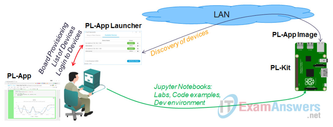
Objectives
- Part 1: Setting up the Prototyping Lab with the Raspberry Pi
- Part 2: Set up the PL-App Application
- Part 3: (Challenge) Implement an International Morse code Help Signaler
Background / Scenario
In this lab you will learn more about how the Raspberry Pi can be used together with the PL-App to write an application that interacts with external electronics using the GPIO ports on the Raspberry Pi. In Part 1, you will build a simple circuit with an external LED that is connected to the GPIO ports on the Raspberry PI. In Part 2, you will use the PL-App visual programming tool, Blockly, to create a program to that will blink the LED when uploaded and run on the Raspberry Pi.
Part 3 challenges you to modify the Blockly code to have the LED blink the International Morse code signal for help.
Required Resources
- PC with Internet Access
- Raspberry Pi with power cable and either a wired or wireless network connection
- Raspberry Pi that is configured and imaged for PL-App access
Part 1: Setting up the Prototyping Lab with the Raspberry Pi
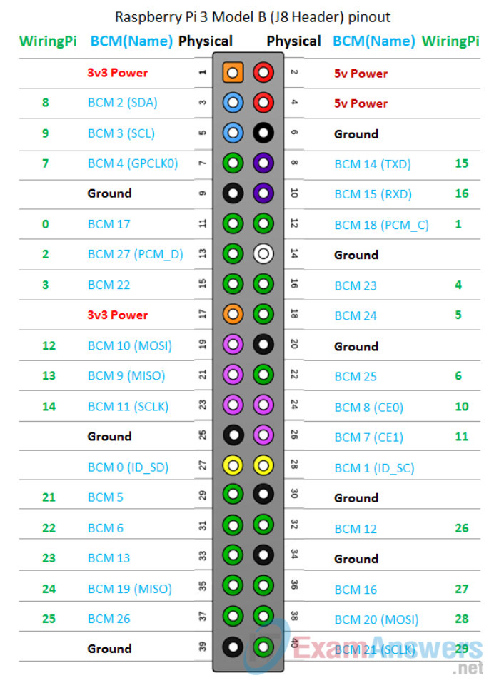
It is important to know how the GPIO pins on the Raspberry Pi are numbered and accessed. The Raspberry Pi 3 model B uses 3 different pin numbering schemes described in the figure below. The recommended one is the BCM pin numbering scheme:
Step 1: Build the prototyping circuit on the breadboard.
Note: The Raspberry Pi should not be powered on when building the prototyping circuit.
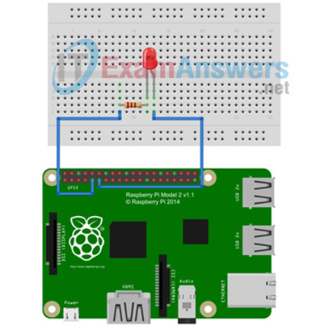
- Select 1 – 330 Ohm (Ω) resistor, 1 LED, 1 red jumper wire, 1 black jumper wire from the Raspberry Pi starter kit.
- Insert the LED onto the breadboard. The cathode leg is connected to c13 and the anode leg is to be connected c14.
- Insert the resistor onto the breadboard into the b9 and b13 connectors.
Step 2: Complete the prototyping circuit by connecting it to the Raspberry Pi.
Note: The GPIO pins on the Raspberry Pi are male. If available, use male to Female jumper wires to connect from the breadboard to the Raspberry Pi. Otherwise, use the GPIO ribbon cable, provided in the starter kit, to convert the GPIO pins to female connectors.
- Connect one end of the black jumper wire to the breadboard a9 connector and the other end to GPIO Physical pin 9 on the Raspberry Pi.
- Connect one end of the red jumper wire to the breadboard a14 connector and the other end to GPIO Physical pin 11 (BCM17) on the Raspberry Pi.
Part 2: Set up the PL-App Application
Step 1: Create a Visual (Blockly) Programming cell.
a. Enter the Code cell below and turn it from a default Python code cell to a Visual Programming cell by clicking on the Blockly icon in the toolbar.

Step 3: Create a Visual (Blockly) program
1. The code cell now supports Visual Programming using Blockly. Add a new Print block and Text block to the canvas.
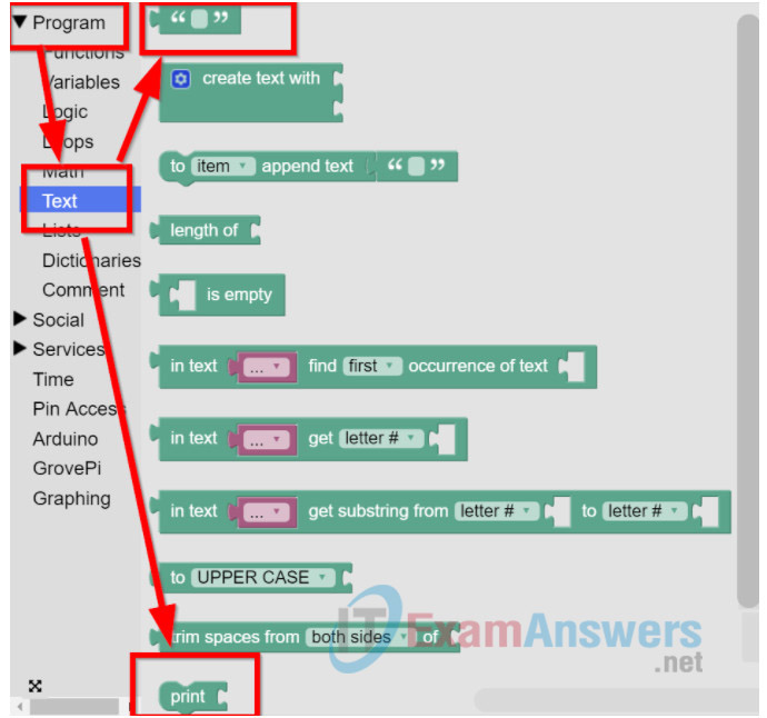
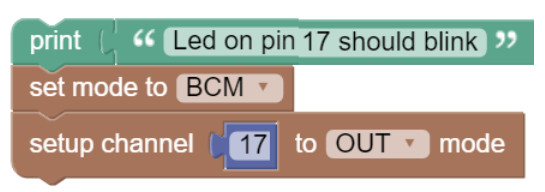
2. Connect the Text block to the Print block. Add to the Text block the follwing text: Led on pin BCM 17 should blink

3. To control the GPIO pins of the Raspberry Pi, first you need to configure the pin numbering scheme to BCM. From the Blockly Pin Access menu, select the set mode to block and add right after the print block. Change its value to BCM.

4. Configure the GPIO pin where the LED is physically connected (physical pin11/BCM17) to be an OUTput type. Select the setup channel block from the Pin Access menu and add it to the canvas. The first number – the channel – represents the GPIO pin (with the specified pin numbering scheme – defined with the block before to be BCM) you want to configure (BCM17), while the second parameter is the direction – OUTput or INput – of that pin. Since we want to control the state of the LED from the Raspberry Pi, the mode is in this case OUTput.
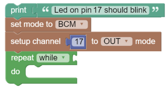
5. Add a repeat while loop by selecting Program->Loops, and move it to the canvas.
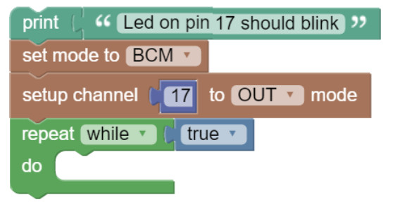
6. Select Program->Logic and drag the true block to the end of the repeat while block.
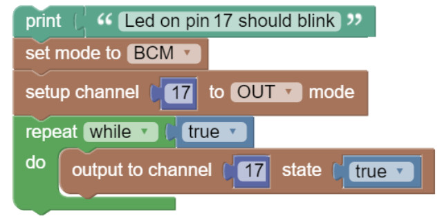
7. Add a output to channel block by selecting Pin Access. Drag the output to channel block inside the repeat while loop. From the Program->Logic menu, select the true block and add it to the output to channel block. This will turn on the GPIO pin and provide 3.3V to power the LED.
8. Add a delay block by selecting from the Time menu the sleep block to generate a delay between the execution of the blocks. Drag it inside the repeat while loop below the output to channel block. Set the delay to 0.5 seconds.
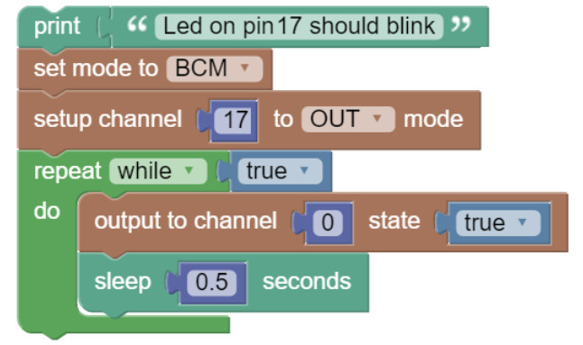
9. Right click on the output to channel and sleep blocks to duplicate them.
10. For the duplicated output to channel block, change the state to false.
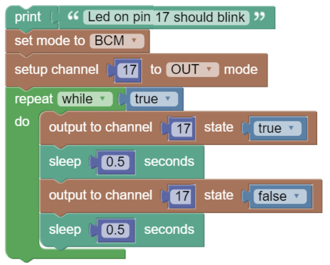
11. Examine the generated Python script on the right side of the Visual Programming code cell.
Step 4: Run the Application.
1. In the code cell, click on the Play button at the top left corner of the cell. The Python code will be executed on the Raspberry Pi and the LED should start blinking.

Note: If the LED does not blink, disconnect the Raspberry Pi from its power source before troubleshooting the circuit.
2. Click the Stop button to stop the program. Note: Depending on the cycle in the program the LED may continue to illuminate even though the program has terminated. Try restarting the application and stopping again during the off cycle.
Part 3: (Challenge) Implement an International Morse code Help Signaler
Modify the Blockly program you created in Part 2 to have the LED blink the International Morse code signal for help (SOS). Hint: Review the unit lengths listed in the chart.

Reflection:
Look at the various options under the Blockly Program->Loops controls. How might the application be modified to have the program execute the loop for a defined number of times or based on a periodic interval as opposed to quitting the application?
