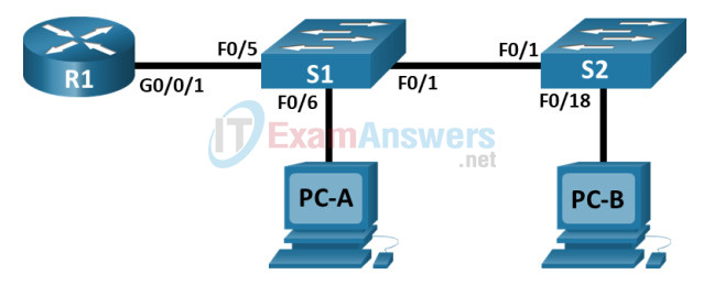
4.4.9 Packet Tracer – Troubleshoot Inter-VLAN Routing – Physical Mode Answers
Topology

Addressing Table
| Device | Interface | IP Address | Subnet Mask | Default Gateway |
|---|---|---|---|---|
| R1 | G0/0/1.3 | 10.3.0.1 | 255.255.255.0 | N/A |
| G0/0/1.4 | 10.4.0.1 | 255.255.255.0 | ||
| G0/0/1.13 | 10.13.0.1 | 255.255.255.0 | ||
| S1 | VLAN 3 | 10.3.0.11 | 255.255.255.0 | 10.3.0.1 |
| S2 | VLAN 3 | 10.3.0.12 | 255.255.255.0 | 10.3.0.1 |
| PC-A | NIC | 10.4.0.50 | 255.255.255.0 | 10.4.0.1 |
| PC-B | NIC | 10.13.0.50 | 255.255.255.0 | 10.13.0.1 |
VLAN Table
| VLAN | Name | Interface Assigned |
|---|---|---|
| 3 | Management | S1: VLAN 3 S2: VLAN 3 |
| 4 | Operations | S1: F0/6 |
| 7 | ParkingLot | S1: F0/2-4, F0/7-24, G0/1-2 S2: F0/2-17, F0/19-24, G0/1-2 |
| 8 | Native | N/A |
| 13 | Maintenance | S2: F0/18 |
Objectives
- Part 1: Evaluate Network Operation
- Part 2: Gather Information, Create an Action Plan, and Implement Corrections
Background / Scenario
All the network devices in this Packet Tracer Physical Mode (PTPM) activity have been preconfigured to include intentional errors that are keeping the inter-VLAN routing from working. Your task is to evaluate the network, identify, and correct the configuration errors to restore full inter-VLAN connectivity. You may find errors with the configurations which are not directly related to inter-VLAN routing. These errors impact the ability of the network devices to perform this function.
Note: The design approach used in this activity is to assess your ability to configure and troubleshoot interVLAN routing only. This design may not reflect networking best practices.
Instructions
Part 1: Evaluate Network Operation
Requirements:
- No VLAN 7 traffic is allowed on the trunks because there are no devices in VLAN 7.
- VLAN 8 is the native VLAN.
- All trunks are static.
- End to end connectivity.
a. Use the laptop computer and appropriate cable to console into the network devices for testing and configuration purposes. The login password on all network devices is “cisco” and the enable password is “class”. You can click and drag the console connection from the console port of one device to another, but you will have to start a new terminal session.
b. Use the ping command to test the following criteria and record the results in the table below.
| From | To | Ping Results |
|---|---|---|
| R1 | S1 VLAN 3 (10.3.0.11) | Unsuccessful |
| S2 VLAN 3 (10.3.0.12) | Unsuccessful | |
| PC-A (10.4.0.50) | Unsuccessful | |
| PC-B (10.13.0.50) | Unsuccessful | |
| S1 | S2 VLAN 3 (10.3.0.12) | Unsuccessful |
| PC-A (10.4.0.50) | Unsuccessful | |
| PC-B (10.13.0.50) | Unsuccessful | |
| S2 | PC-A (10.4.0.50) | Unsuccessful |
| PC-B (10.13.0.50) | Unsuccessful |
Part 2: Gather Information, Create an Action Plan, and Implement Corrections
a. For each requirement that is not met, gather information by examining the running configuration and the routing tables to develop a hypothesis for what is causing the malfunction.
b. Create an action plan that you think will fix the issue. Develop a list of all the commands you intend to issue to fix the issue, and a list of all the commands you need to revert the configuration, should your action plan fail to correct the issue.
Hint: If you need to reset a switchport to default configuration, use the default interface interface name command.
As an example for F0/10:
S1(config)# default interface f0/10
c. Execute your action plans one at a time for each criterion that fails and record the fix actions.
————-
Router R1:
————-
configure terminal
interface g0/0/1.8
encapsulation dot1q 8 native
exit
————-
Switch S1:
————-
configure terminal
default interface f0/5
interface f0/5
switchport mode trunk
switchport trunk native vlan 8
switchport trunk allowed vlan 3,4,8,13
interface f0/1
switchport trunk allowed vlan 3,13
switchport trunk native vlan 8
vlan 13
name Maintenance
exit
————-
Switch S2:
————-
configure terminal
interface f0/1
switchport trunk allowed vlan 3,13
exit

Here is the message between the switches:
%CDP-4-NATIVE_VLAN_MISMATCH: Native VLAN mismatch discovered on FastEthernet0/1 (1), with S2 FastEthernet0/1 (8).
Got it. I mistyped the following. Thank you.
interface f0/1
switchport trunk allowed vlan 3,13
switchport trunk native vlan 8
0% Completed