9.1.3 Packet Tracer - Identify MAC and IP Addresses
Instructor Note: Red font color or gray highlights indicate text that appears in the instructor copy only.
Topology
9.1.3 Packet Tracer - Identify MAC and IP Addresses - ILM
Objectives
Part 1: Gather PDU Information for Local Network Communication
Part 2: Gather PDU Information for Remote Network Communication
Background
This activity is optimized for viewing PDUs. The devices are already configured. You will gather PDU information in simulation mode and answer a series of questions about the data you collect.
Instructions
Part 1: Gather PDU Information for Local Network Communication
Note: Review the Reflection Questions in Part 3 before proceeding with Part 1. It will give you an idea of the type of information you will need to gather.
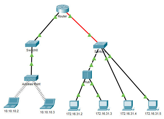
Step 1: Gather PDU information as a packet travels from 172.16.31.5 to 172.16.31.2.
a. Click 172.16.31.5 and open the Command Prompt.
b. Enter the ping 172.16.31.2 command.
c. Switch to simulation mode and repeat the ping 172.16.31.2 command. A PDU appears next to 172.16.31.5.
d. Click the PDU and note the following information from the OSI Model and Outbound PDU Layer tabs:
- Destination MAC Address: 000C:85CC:1DA7
- Source MAC Address: 00D0:D311:C788
- Source IP Address: 172.16.31.5
- Destination IP Address: 172.16.31.2
- At Device: 172.16.31.5
e. Click Capture / Forward (the right arrow followed by a vertical bar) to move the PDU to the next device. Gather the same information from Step 1d. Repeat this process until the PDU reaches its destination. Record the PDU information you gathered into a spreadsheet using a format like the table shown below:
Example Spreadsheet Format
| At Device | Dest. MAC | Src MAC | Src IPv4 | Dest IPv4 |
|---|---|---|---|---|
| 172.16.31.5 | 000C:85CC:1DA7 | 00D0:D311:C788 | 172.16.31.5 | 172.16.31.2 |
| Switch1 | 000C:85CC:1DA7 | 00D0:D311:C788 | N/A | N/A |
| Hub | N/A | N/A | N/A | N/A |
| 172.16.31.2 | 00D0:D311:C788 | 000C:85CC:1DA7 | 172.16.31.2 | 172.16.31.5 |
Step 2: Gather additional PDU information from other pings.
Repeat the process in Step 1 and gather the information for the following tests:
• Ping 172.16.31.2 from 172.16.31.3.
• Ping 172.16.31.4 from 172.16.31.5.
Return to Realtime mode.
Part 2: Gather PDU Information for Remote Network Communication
In order to communicate with remote networks, a gateway device is necessary. Study the process that takes place to communicate with devices on the remote network. Pay close attention to the MAC addresses used.
Step 1: Gather PDU information as a packet travels from 172.16.31.5 to 10.10.10.2.
a. Click 172.16.31.5 and open the Command Prompt.
b. Enter the ping 10.10.10.2 command.
c. Switch to simulation mode and repeat the ping 10.10.10.2 command. A PDU appears next to 172.16.31.5.
d. Click the PDU and note the following information from the Outbound PDU Layer tab:
• Destination MAC Address: 00D0:BA8E:741A
• Source MAC Address: 00D0:D311:C788
• Source IP Address: 172.16.31.5
• Destination IP Address: 10.10.10.2
• At Device: 172.16.31.5
What device has the destination MAC that is shown?
The router
e. Click Capture / Forward (the right arrow followed by a vertical bar) to move the PDU to the next device. Gather the same information from Step 1d. Repeat this process until the PDU reaches its destination. Record the PDU information you gathered from pinging 172.16.31.5 to 10.10.10.2 into a spreadsheet using a format like the sample table shown below:
| At Device | Dest. MAC | Src MAC | Src IPv4 | Dest IPv4 |
|---|---|---|---|---|
| 172.16.31.5 | 00D0:BA8E:741A | 00D0:D311:C788 | 172.16.31.5 | 10.10.10.2 |
| Switch1 | 00D0:BA8E:741A | 00D0:D311:C788 | N/A | N/A |
| Router | 0060:2F84:4AB6 | 00D0:588C:2401 | 172.16.31.5 | 10.10.10.2 |
| Switch0 | 0060:2F84:4AB6 | 00D0:588C:2401 | N/A | N/A |
| Access Point | N/A | N/A | N/A | N/A |
| 10.10.10.2 | 00D0:588C:2401 | 0060:2F84:4AB6 | 10.10.10.2 | 172.16.31.5 |
Part 2: Reflection Questions
Answer the following questions regarding the captured data:
1. Were there different types of wires used to connect devices?
2. Did the wires change the handling of the PDU in any way?
3. Did the Hub lose any of the information given to it?
4. What does the Hub do with MAC addresses and IP addresses?
5. Did the wireless Access Point do anything with the information given to it?
6. Was any MAC or IP address lost during the wireless transfer?
7. What was the highest OSI layer that the Hub and Access Point used?
8. Did the Hub or Access Point ever replicate a PDU that was rejected with a red “X”?
9. When examining the PDU Details tab, which MAC address appeared first, the source or the destination?
10. Why would the MAC addresses appear in this order?
11. Was there a pattern to the MAC addressing in the simulation?
12. Did the switches ever replicate a PDU that was rejected with a red “X”?
13. Every time that the PDU was sent between the 10 network and the 172 network, there was a point where the MAC addresses suddenly changed. Where did that occur?
14. Which device uses MAC addresses starting with 00D0?
15. To what devices did the other MAC addresses belong?
16. Did the sending and receiving IPv4 addresses switch in any of the PDUs?
17. If you follow the reply to a ping, sometimes called a pong, do the sending and receiving IPv4 addresses switch?
18. What is the pattern to the IPv4 addressing in this simulation?
19. Why do different IP networks need to be assigned to different ports of a router?
20. If this simulation was configured with IPv6 instead of IPv4, what would be different?
Download Packet Tracer (.pka) file:

13.1.3 Packet Tracer - Identify MAC and IP Addresses
Objectives
- Part 1: Gather PDU Information for a Local Network Communication
- Part 2: Gather PDU Information for a Remote Network Communication
Background
If you are interested in a career in network administration or network security, it is important to understand normal network communication processes. In this Packet Tracer activity, you will inspect Ethernet frames and IP packets at different points in the network as they travel from source to destination. You will focus on the way that the MAC and IP addresses change depending on the destination (local or remote) and the place where the PDUs are captured.
Packet Tracer has a simulation mode which will enable you to investigate details about how PDUs travel on networks. It enables you to check the Layer 2 MAC addressing and Layer 3 IPv4 addressing of the PDUs at different locations in the network as the PDUs flow from source to destination.
This activity is optimized for viewing PDUs as they travel on local and remote networks. You will gather PDU information in PT simulation mode and answer a series of questions about the data you collect. No device configuration is required.
Instructions
Part 1: Gather PDU Information for a Local Network Communication
In this part, you will study how a device on a local network does not need a default gateway to communicate with another device on the same local network.
Note: Review the Reflection Questions in Part 3 before proceeding with this part. It will give you an idea of the type of information you will need to gather.
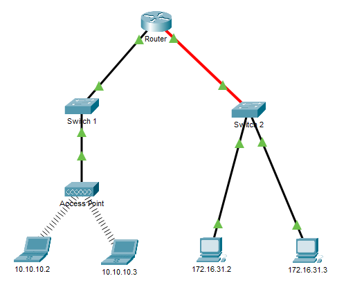
a. Click host 172.16.31.3 and open the Command Prompt.
b. Enter the ping 172.16.31.2 command. This command will issue a series of ICMP echo request packets to the destination. If the packets reach the destination, it will send echo-reply messages pack to the source of the ping requests.
c. Click the Simulation mode button to switch to simulation mode. Repeat the ping 172.16.31.2 command. An envelope icon that represents a PDU appears next to 172.16.31.3.
d. Click the PDU and locate the following information in both the OSI Model and Outbound PDU Details tabs. The Outbound PDU Details tab shows simplified packet and frame headers for the PDU. You should observe the following details regarding addressing for the PDU.
- At Device: 172.16.31.3
- Source MAC Address: 0060.7036.2849
- Destination MAC Address: 000C:85CC:1DA7
- Source IP Address: 172.16.31.3
- Destination IP Address: 172.16.31.2
e. Click Capture / Forward (the right arrow followed by a vertical bar) and the PDU moves to the next step in its journey. Use the OSI model tab to gather the same information from Step 1d. Repeat this process until the PDU reaches its destination. For each step on the path to delivery, record the information for each PDU into a spreadsheet that uses a format like the table shown below. The information for the first step is shown in the table.
Example Spreadsheet Format
| At Device | Src MAC | Dest. MAC | Src IPv4 | Dest IPv4 |
|---|---|---|---|---|
| 172.16.31.3 | 0060.7036.2849 | 000C:85CC:1DA7 | 172.16.31.3 | 172.16.31.2 |
| Switch 2 | 0060.7036.2849 | 000C:85CC:1DA7 | N/A | N/A |
| 172.16.31.2 (in) | 000C:85CC:1DA7 | 000C:85CC:1DA7 | 172.16.31.3 | 172.16.31.2 |
| 172.16.31.2 (out) | 0060.7036.2849 | 0060.7036.2849 | 172.16.31.2 | 172.16.31.3 |
f. You will notice that the information for the inbound PDU is unchanged.
In the PDU information window, click the tab for the outbound PDU. How does the addressing differ, and why? Record the addressing in your table.
The source and destination address are reversed in both the frame and packet because this PDU will be sent back to host 172.16.31.3. This message will be a ping echo-reply.
g. Return to Realtime mode.
Part 2: Gather PDU Information for a Remote Network Communication
To communicate with remote networks, a gateway device is necessary. The gateway device connects two or more networks together. In this part, you will study the process that takes place when one device communicates with another device that is on a remote network. Pay close attention to the MAC addresses used.
Note: Move your mouse over the Router. You will see information about the addressing of the router interfaces. Refer to these addresses as you observe the PDU flow through the router.
a. Return to the Command Prompt for 172.16.31.3.
b. Enter the ping 10.10.10.2 command. The first couple of pings may time out.
c. Switch to Simulation mode and repeat the ping 10.10.10.2 command. A PDU appears next to 172.16.31.3.
d. Click the PDU and note the following information tab:
- At Device: 172.16.31.3
- Source MAC Address: 0060.7036.2849
- Destination MAC Address: 00D0:BA8E:741A
- Source IP Address: 172.16.31.3
- Destination IP Address: 10.10.10.2
What device and interface has the destination MAC address that is shown?
The router interface FasteEthernet1/0
e. Click Capture / Forward (the right arrow followed by a vertical bar) to move the PDU to the next device. Gather the same information from Step 1d. Repeat this process until the PDU reaches its destination. Record the PDU information you gathered from pinging 172.16.31.5 to 10.10.10.2 into a spreadsheet using a format like the sample table shown below. Enter details for both the inbound and outbound PDUs at the Router.
| At Device | Src MAC | Dest. MAC | Src IPv4 | Dest IPv4 |
|---|---|---|---|---|
| 172.16.31.3 | 0060.7036.2849 | 00D0:BA8E:741A | 172.16.31.3 | 10.10.10.2 |
| Switch 2 | 0060.7036.2849 | 00D0:BA8E:741A | N/A | N/A |
| Router (in) | 0060.7036.2849 | 00D0:BA8E:741A | 172.16.31.3 | 10.10.10.2 |
| Router (out) | 00D0:588C:2401 | 0060:2F84:4AB6 | 172.16.31.3 | 10.10.10.2 |
| Switch 1 | 00D0:588C:2401 | 0060:2F84:4AB6 | N/A | N/A |
| Access Point | N/A | N/A | N/A | N/A |
| 10.10.10.2 | 0060:2F84:4AB6 | 00D0:588C:2401 | 10.10.10.2 | 172.16.31.5 |
f. Repeat the process for the echo-reply message that originates from host 10.10.10.2. Complete the table for each step.
| At Device | Src MAC | Dest. MAC | Src IPv4 | Dest IPv4 |
|---|---|---|---|---|
| 10.10.10.2 | 0060:2F84:4AB6 | 00D0:588C:2401 | 10.10.10.2 | 172.16.31.3 |
| Access Point | N/A | N/A | N/A | N/A |
| Switch 1 | 0060:2F84:4AB6 | 00D0:588C:2401 | N/A | N/A |
| Router (in) | 0060:2F84:4AB6 | 00D0:588C:2401 | 10.10.10.2 | 172.16.31.3 |
| Router (out) | 00D0.BA8E.741A | 0060.7036.2849 | 10.10.10.2 | 172.16.31.3 |
| Switch 1 | 00D0.BA8E.741A | 0060.7036.2849 | N/A | N/A |
| Access Point | N/A | N/A | N/A | N/A |
| 10.10.10.2 | 00D0.BA8E.741A | 0060.7036.2849 | 10.10.10.2 | 172.16.31.5 |
Reflection Questions
Answer the following questions regarding the captured data:
1. What different types of cables/media were used to connect devices?
2. Did the cables change the handling of the PDU in any way?
3. Did the wireless Access Point do anything to the PDUs that it received?
4. Was PDU addressing changed by the access point?
5. What was the highest OSI layer that the Access Point used?
6. At what Layer of the OSI model do cables and access points operate?
7. When examining the PDU Details tab, which MAC address appeared first, the source or the destination?
8. Sometimes PDUs were marked with red Xs while others had green check marks. What is the significance of these markings?
9. Every time that the PDU was sent between the 10 network and the 172 network, there was a point where the MAC addresses suddenly changed. Where did that occur?
10. Which device uses MAC addresses that start with 00D0:BA?
11. What devices did the other MAC addresses belong to?
12. Did the sending and receiving IPv4 addresses change in any of the PDUs?
13. When you follow the reply to a ping, sometimes called a pong, what happens to the source and destination addresses?
14. Why do you think the interfaces of the router are part of two different IP networks?
15. Which IP networks are connected by the router?