
10.4.3 Packet Tracer - Basic Device Configuration Instructor Version
Topology
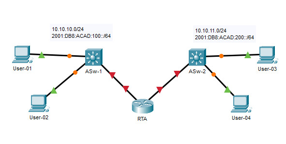
10.4.3 Packet Tracer - Basic Device Configuration
Addressing Table
| Device | Interface | IP Address | Default Gateway |
|---|---|---|---|
| College | G0/0 | 128.107.20.1/24 | N/A |
| G0/0 | 2001:db8:a::1/64 | ||
| G0/0 | FE80::1 | ||
| G0/1 | 128.107.30.1/24 | N/A | |
| G0/1 | 2001:db8:b::1/64 | ||
| G0/1 | FE80::1 | ||
| Class-A | VLAN 1 | 128.107.20.2/24 | 128.107.20.1 |
| Class-B | VLAN 1 | 128.107.30.15/24 | 128.107.30.1 |
| Student-1 | NIC | 128.107.20.25/24 | 128.107.20.1 |
| Student-1 | NIC | 2001:db8:a::2/64 | FE80::1 |
| Student-2 | NIC | 128.107.20.30/24 | 128.107.20.1 |
| Student-2 | NIC | 2001:db8:a::3/64 | FE80::1 |
| Student-3 | NIC | 128.107.30.25/24 | 128.107.30.1 |
| Student-3 | NIC | 2001:db8:b::2/64 | FE80::1 |
| Student-4 | NIC | 128.107.30.30/24 | 128.107.30.1 |
| Student-4 | NIC | 2001:db8:b::3/64 | FE80::1 |
Objectives
- Complete the network documentation.
- Perform basic device configurations on a router and a switch.
- Verify connectivity and troubleshoot any issues.
Scenario
Your network manager is impressed with your performance in your job as a LAN technician. She would like you to demonstrate your ability to configure a router that connects two LANs. Your tasks include configuring basic settings on a router and a switch using the Cisco IOS. You will also configure IPv6 addresses on network devices and hosts. You will then verify the configurations by testing end-to-end connectivity. Your goal is to establish connectivity between all devices.
Note: The VLAN1 interface on Class-A will not be reachable over IPv6.
In this activity you will configure the College router, Class-B switch, and the PC hosts.
Note: Packet Tracer will not score some configured values, however these values are required to accomplish full connectivity in the network.
Requirements
- Provide the missing information in the Addressing Table.
- Name the router College and the second switch Class-B. You will not be able to access the Class-A switch.
Router(config)# hostname College
Switch(config)# hostname Class-B
- Use cisco as the user EXEC password for all lines.
College(config)# line console 0
College(config-line)# password cisco
College(config-line)# login
College(config-line)# line vty 0 15
College(config-line)# password cisco
College(config-line)# login
Class-B(config)# line console 0
Class-B(config-line)# password cisco
Class-B(config-line)# login
Class-B(config-line)# line vty 0 15
Class-B(config-line)# password cisco
Class-B(config-line)# login
- Use class as the encrypted privileged EXEC password.
College(config)# enable secret class
Class-B(config)# enable secret class
- Encrypt all plaintext passwords.
College(config)# service password-encryption
Class-B(config)# service password-encryption
- Configure an appropriate banner.
College(config)# banner motd #Unauthorized access to this device is prohibited!#
Class-B(config)# banner motd #Unauthorized access to this device is prohibited!#
- Configure IPv4 and IPv6 addressing for the College router according to the Addressing Table.
College(config)# ipv6 unicast-routing
College(config)# interface gigabitethernet 0/0
College(config-if)# ip address 128.107.20.1 255.255.255.0
College(config-if)# ipv6 address 2001:db8:a::1/64
College(config-if)# ipv6 address fe80::1 link-local
College(config-if)# no shutdown
College(config-if)# interface gigabitethernet 0/1
College(config-if)# ip address 128.107.30.1 255.255.255.0
College(config-if)# ipv6 address 2001:db8:b::1/64
College(config-if)# ipv6 address fe80::1 link-local
College(config-if)# no shutdown
- Configure IPv4 and IPv6 addressing for the Class-B switch according to the Addressing Table.
Class-B(config)# interface vlan 1
Class-B(config-if)# ip address 128.107.30.15 255.255.255.0
Class-B(config-if)# no shutdown
Class-B(config-if)# exit
Class-B(config)# ip default-gateway 128.107.30.1
- The hosts are partially configured. Complete the IPv4 addressing, and fully configure the IPv6 addresses according to the Addressing Table.
- Document interfaces with descriptions, including the Class-B VLAN 1 interface.
College(config)# interface gigabitethernet 0/0
College(config-if)# description Link to Class-A
College(config-if)# interface gigabitethernet 0/1
College(config-if)# description Link to Class-B
Class-B(config)# interface vlan 1
Class-B(config-if)# description Vlan 1
- Save your configurations.
College# copy running-config startup-config
Class-B# copy running-config startup-config
- Verify connectivity between all devices. All devices should be able to ping all other devices with IPv4 and IPv6.
C:\> ping 128.107.30.30
C:\> ping 2001:db8:b::3
- Troubleshoot and document any issues.
- Implement the solutions necessary to enable and verify full end-to-end connectivity.
Note: Click Check Results button to see your progress. Click the Reset Activity button to generate a new set of requirements.
Device Configs - Final
ROUTER College
! ==============================================================
!--- 10.4.3 Packet Tracer - Basic Device Configuration
!--- ANSWER SCRIPT FOR ROUTER College
!--- Usage: copy this whole file and paste it into the router terminal (start at the user EXEC ">" prompt). Every line beginning with "!" is a comment; IOS ignores it, so pasting a comment by accident is harmless.
!--- Note: this activity is randomized - Reset Activity generates new names and addresses. The values below match the instructor sample; replace them with the values in your own Addressing Table.
! ==============================================================

enable
configure terminal

! --------------------------------------------------------------
!--- Requirements: basic device settings.
! --------------------------------------------------------------

!--- Name the router College.
hostname College

!--- Use class as the encrypted privileged EXEC password.
enable secret class

!--- Use cisco as the user EXEC password for all lines - console.
line console 0
 password cisco
 login
 exit

!--- Use cisco as the user EXEC password for all lines - vty 0 15.
line vty 0 15
 password cisco
 login
 exit

!--- Encrypt all plaintext passwords.
service password-encryption

!--- Configure an appropriate banner.
banner motd #Unauthorized access to this device is prohibited!#

! --------------------------------------------------------------
!--- Requirements: IPv4 and IPv6 addressing and interface descriptions.
! --------------------------------------------------------------

!--- Enable IPv6 routing so the router forwards IPv6 between the two LANs.
ipv6 unicast-routing

!--- G0/0: IPv4, IPv6 GUA, link-local FE80::1 and description (LAN toward Class-A).
interface gigabitethernet 0/0
 description Link to Class-A
 ip address 128.107.20.1 255.255.255.0
 ipv6 address 2001:db8:a::1/64
 ipv6 address fe80::1 link-local
 no shutdown
 exit

!--- G0/1: IPv4, IPv6 GUA, link-local FE80::1 and description (LAN toward Class-B).
interface gigabitethernet 0/1
 description Link to Class-B
 ip address 128.107.30.1 255.255.255.0
 ipv6 address 2001:db8:b::1/64
 ipv6 address fe80::1 link-local
 no shutdown
 exit

end

! --------------------------------------------------------------
!--- Save the configuration to NVRAM. (Press Enter when prompted for the destination filename.)
! --------------------------------------------------------------
copy running-config startup-config


! ==============================================================
!--- Verification:
!---   show ip interface brief    -> G0/0 and G0/1 up/up with their IPv4 addresses
!---   show ipv6 interface brief  -> GUA and link-local FE80::1 on both interfaces
!---   show ipv6 route            -> both IPv6 LANs (2001:db8:a::/64, 2001:db8:b::/64) are connected
!---   ping 128.107.30.15         -> reaches the Class-B switch
!---   ping 2001:db8:b::2         -> reaches Student-3 over IPv6
! ==============================================================
SWITCH Class-B
! ==============================================================
!--- 10.4.3 Packet Tracer - Basic Device Configuration
!--- ANSWER SCRIPT FOR SWITCH Class-B
!--- Usage: copy this whole file and paste it into the switch terminal (start at the user EXEC ">" prompt). Every line beginning with "!" is a comment; IOS ignores it, so pasting a comment by accident is harmless.
!--- Note: this activity is randomized - Reset Activity generates new names and addresses. The values below match the instructor sample; replace them with the values in your own Addressing Table. The Class-A switch cannot be accessed, so it has no script.
! ==============================================================

enable
configure terminal

! --------------------------------------------------------------
!--- Requirements: basic device settings.
! --------------------------------------------------------------

!--- Name the second switch Class-B.
hostname Class-B

!--- Use class as the encrypted privileged EXEC password.
enable secret class

!--- Use cisco as the user EXEC password for all lines - console.
line console 0
 password cisco
 login
 exit

!--- Use cisco as the user EXEC password for all lines - vty 0 15 (a 2960 switch has 16 vty lines).
line vty 0 15
 password cisco
 login
 exit

!--- Encrypt all plaintext passwords.
service password-encryption

!--- Configure an appropriate banner.
banner motd #Unauthorized access to this device is prohibited!#

! --------------------------------------------------------------
!--- Requirements: IPv4 addressing and the VLAN 1 description.
! --------------------------------------------------------------

!--- VLAN 1: IPv4 address from the Addressing Table, a description, and activate it.
interface vlan 1
 description Vlan 1
 ip address 128.107.30.15 255.255.255.0
 no shutdown
 exit

!--- Default gateway (College G0/1) so the switch can reply to devices on the other LAN. Packet Tracer may not score it, but full connectivity needs it.
ip default-gateway 128.107.30.1

end

! --------------------------------------------------------------
!--- Save the configuration to NVRAM. (Press Enter when prompted for the destination filename.)
! --------------------------------------------------------------
copy running-config startup-config


! ==============================================================
!--- Verification:
!---   show ip interface brief  -> Vlan1 up/up with 128.107.30.15
!---   ping 128.107.30.1        -> reaches the default gateway (College G0/1)
!---   ping 128.107.20.25       -> reaches Student-1 on the other LAN
!--- Note: the switch VLAN 1 interface is IPv4 only in this activity; the Addressing Table gives no IPv6 address for Class-A or Class-B.
! ==============================================================


