1.4.7 Packet Tracer – Configure Router Interfaces (Instructor Version)
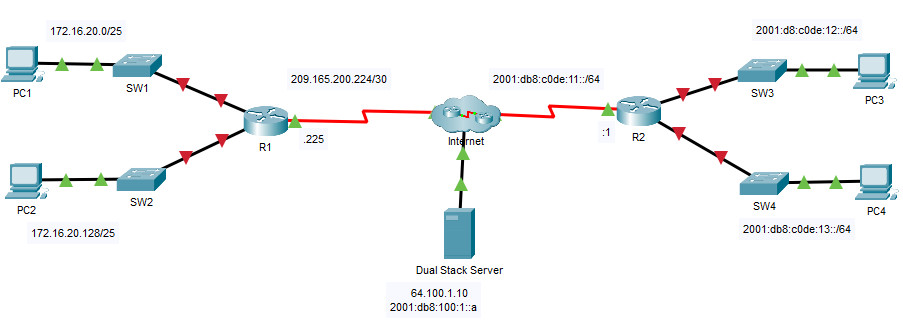
Addressing Table
| Device | Interface | IP Address/Prefix | Default Gateway |
|---|---|---|---|
| R1 | G0/0 | 172.16.20.1 /25 | N/A |
| G0/1 | 172.16.20.129 /25 | N/A | |
| S0/0/0 | 209.165.200.225 /30 | N/A | |
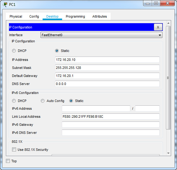
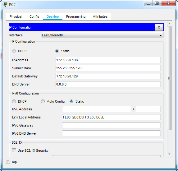
| PC1 | NIC | 172.16.20.10 /25 | 172.16.20.1 |
| PC2 | NIC | 172.16.20.138 /25 | 172.16.20.129 |
| R2 | G0/0 | 2001:db8:c0de:12::1/64 | N/A |
| G0/1 | 2001:db8:c0de:13::1/64 | N/A | |
| S0/0/1 | 2001:db8:c0de:11::1/64 | N/A | |
| fe80::2 | N/A | ||
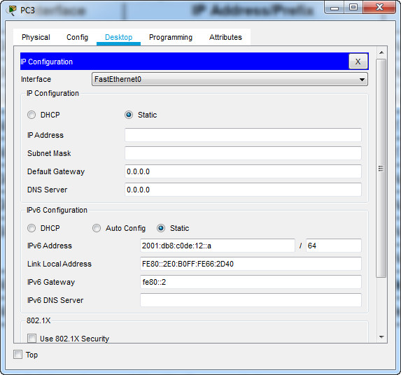
| PC3 | NIC | 2001:db8:c0de:12::a/64 | fe80::2 |
| PC4 | NIC | 2001:db8:c0de:13::a/64 | fe80::2 |
Objectives
- Part 1: Configure IPv4 Addressing and Verify Connectivity
- Part 2: Configure IPv6 Addressing and Verify Connectivity
Background
Routers R1 and R2 each have two LANs. Your task is to configure the appropriate addressing on each device and verify connectivity between the LANs.
Note: The user EXEC password is cisco. The privileged EXEC password is class.
Instructions
Part 1: Configure IPv4 Addressing and Verify Connectivity
Step 1: Assign IPv4 addresses to R1 and LAN devices.
Referring to the Addressing Table, configure IP addressing for R1 LAN interfaces, PC1 and PC2. The serial interface has already configured.
R1>enable
Password:
R1#configure terminal
R1(config)#interface g0/0
R1(config-if)#ip address 172.16.20.1 255.255.255.128
R1(config-if)#no shutdown

R1(config-if)#interface g0/1
R1(config-if)#ip address 172.16.20.129 255.255.255.128
R1(config-if)#no shutdown
R1(config-if)#
Step 2: Verify connectivity.
PC1 and PC2 should be able to ping each other and the Dual Stack Server.
C:\>PING 172.16.20.138

Pinging 172.16.20.138 with 32 bytes of data:

Request timed out.
Reply from 172.16.20.138: bytes=32 time<1ms TTL=127
Reply from 172.16.20.138: bytes=32 time<1ms TTL=127 Reply from 172.16.20.138: bytes=32 time=13ms TTL=127 Ping statistics for 172.16.20.138: Packets: Sent = 4, Received = 3, Lost = 1 (25% loss), Approximate round trip times in milli-seconds: Minimum = 0ms, Maximum = 13ms, Average = 4ms C:\>ping 64.100.1.10

Pinging 64.100.1.10 with 32 bytes of data:

Request timed out.
Reply from 64.100.1.10: bytes=32 time=2ms TTL=126
Reply from 64.100.1.10: bytes=32 time=13ms TTL=126
Reply from 64.100.1.10: bytes=32 time=1ms TTL=126

Ping statistics for 64.100.1.10:
    Packets: Sent = 4, Received = 3, Lost = 1 (25% loss),
Approximate round trip times in milli-seconds:
    Minimum = 1ms, Maximum = 13ms, Average = 5ms

C:\>
Part 2: Configure IPv6 Addressing and Verify Connectivity
Step 1: Assign IPv6 addresses to R2 and LAN devices.
Referring to the Addressing Table, configure IP addressing for R2 LAN interfaces, PC3 and PC4. The serial interface is already configured.
R2>enable
Password:
R2#configure terminal

R2(config)#interface g0/0
R2(config-if)#ipv6 address 2001:db8:c0de:12::1/64
R2(config-if)#no shutdown
R2(config-if)#exit

R2(config)#interface g0/1
R2(config-if)#ipv6 address 2001:db8:c0de:13::1/64
R2(config-if)#no shutdown
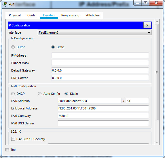
Step 2: Verify connectivity.
PC3 and PC4 should be able to ping each other and the Dual Stack Server.
C:\>ping 2001:db8:c0de:12::a

Pinging 2001:db8:c0de:12::a with 32 bytes of data:

Reply from 2001:DB8:C0DE:12::A: bytes=32 time=13ms TTL=127
Reply from 2001:DB8:C0DE:12::A: bytes=32 time<1ms TTL=127
Reply from 2001:DB8:C0DE:12::A: bytes=32 time<1ms TTL=127
Reply from 2001:DB8:C0DE:12::A: bytes=32 time<1ms TTL=127 Ping statistics for 2001:DB8:C0DE:12::A: Packets: Sent = 4, Received = 4, Lost = 0 (0% loss), Approximate round trip times in milli-seconds: Minimum = 0ms, Maximum = 13ms, Average = 3ms C:\>ping 2001:db8:100:1::a

Pinging 2001:db8:100:1::a with 32 bytes of data:

Reply from 2001:DB8:100:1::A: bytes=32 time=15ms TTL=126
Reply from 2001:DB8:100:1::A: bytes=32 time=7ms TTL=126
Reply from 2001:DB8:100:1::A: bytes=32 time=13ms TTL=126
Reply from 2001:DB8:100:1::A: bytes=32 time=4ms TTL=126

Ping statistics for 2001:DB8:100:1::A:
    Packets: Sent = 4, Received = 4, Lost = 0 (0% loss),
Approximate round trip times in milli-seconds:
    Minimum = 4ms, Maximum = 15ms, Average = 9ms

C:\>

real good
hi, how did you do the cluster?
thanks