Lab – Implement DHCPv4 (Instructor Version)
Topology


Packet Tracer Topology
Addressing Table
| Device | Interface | IP Address | Subnet Mask | Default Gateway |
|---|---|---|---|---|
| R1 | G0/0/0 | 10.0.0.1 | 255.255.255.252 | N/A |
| G0/0/1 | N/A | N/A | ||
| G0/0/1.100 | 192.168.1.1 | 255.255.255.192 | ||
| G0/0/1.200 | 192.168.1.65 | 255.255.255.224 | ||
| G0/0/1.1000 | N/A | N/A | ||
| R2 | G0/0/0 | 10.0.0.2 | 255.255.255.252 | N/A |
| G0/0/1 | 192.168.1.97 | 255.255.255.240 | ||
| S1 | VLAN 200 | 192.168.1.66 | 255.255.255.224 | 192.168.1.65 |
| S2 | VLAN 1 | 192.168.1.98 | 255.255.255.240 | 192.168.1.97 |
| PC-A | NIC | DHCP | DHCP | DHCP |
| PC-B | NIC | DHCP | DHCP | DHCP |
VLAN Table
| VLAN | Name | Interface Assigned |
|---|---|---|
| 1 | N/A | S2: F0/18 |
| 100 | Clients | S1: F0/6 |
| 200 | Management | S1: VLAN 200 |
| 999 | Parking_Lot | S1: F0/1-4, F0/7-24, G0/1-2 |
| 1000 | Native | N/A |
Objectives
- Part 1: Build the Network and Configure Basic Device Settings
- Part 2: Configure and verify two DHCPv4 Servers on R1
- Part 3: Configure and verify a DHCP Relay on R2
Background / Scenario
The Dynamic Host Configuration Protocol (DHCP) is a network protocol that lets network administrators manage and automate the assignment of IP addresses. Without DHCP for IPv4, the administrator must manually assign and configure IP addresses, preferred DNS servers, and default gateways. As the network grows in size, this becomes an administrative problem when devices are moved from one internal network to another.
In this scenario, the company has grown in size, and the network administrators can no longer assign IP addresses to devices manually. Your job is to configure the R1 router to assign IPv4 addresses on two different subnets.
Note: The routers used with CCNA hands-on labs are Cisco 4221 with Cisco IOS XE Release 16.9.4 (universalk9 image). The switches used in the labs are Cisco Catalyst 2960s with Cisco IOS Release 15.2(2) (lanbasek9 image). Other routers, switches, and Cisco IOS versions can be used. Depending on the model and Cisco IOS version, the commands available and the output produced might vary from what is shown in the labs. Refer to the Router Interface Summary Table at the end of the lab for the correct interface identifiers.
Note: Ensure that the routers and switches have been erased and have no startup configurations. If you are unsure contact your instructor.
Instructor Note: Refer to the Instructor Lab Manual for the procedures to initialize and reload devices
Required Resources
- 2 Routers (Cisco 4221 with Cisco IOS XE Release 16.9.4 universal image or comparable)
- 2 Switches (Cisco 2960 with Cisco IOS Release 15.2(2) lanbasek9 image or comparable)
- 2 PCs (Windows with a terminal emulation program, such as Tera Term)
- Console cables to configure the Cisco IOS devices via the console ports
- Ethernet cables as shown in the topology
Instructions
Part 1: Build the Network and Configure Basic Device Settings
In Part 1, you will set up the network topology and configure basic settings on the PC hosts and switches.
Step 1: Establish an addressing scheme
Subnet the network 192.168.1.0/24 to meet the following requirements:
a. One subnet, “Subnet A”, supporting 58 hosts (the client VLAN at R1).
Subnet A:
192.168.1.0/26 (.1 -.63)
Record the first IP address in the Addressing Table for R1 G0/0/1.100. Record the second IP address in the Address Table for S1 VLAN 200 and enter the associated default gateway.
b. One subnet, “Subnet B”, supporting 28 hosts (the management VLAN at R1).
Subnet B:
192.168.1.64/27 (.65-.95)
Record the first IP address in the Addressing Table for R1 G0/0/1.200. Record the second IP address in the Address Table for S1 VLAN 1 and enter the associated default gateway.
c. One subnet, “Subnet C”, supporting 12 hosts (the client network at R2).
Subnet C:
192.168.1.96/28 (.97-.111)
Record the first IP address in the Addressing Table for R2 G0/0/1.
Step 2: Cable the network as shown in the topology.
Attach the devices as shown in the topology diagram, and cable as necessary.
Step 3: Configure basic settings for each router.
a. Assign a device name to the router.
router(config)# hostname R1
b. Disable DNS lookup to prevent the router from attempting to translate incorrectly entered commands as though they were host names.
R1(config)# no ip domain-lookup
c. Assign class as the privileged EXEC encrypted password.
R1(config)# enable secret class
d. Assign cisco as the console password and enable login.
R1(config)# line console 0
R1(config-line)# password cisco
R1(config-line)# login
e. Assign cisco as the VTY password and enable login.
R1(config)# line vty 0 4
R1(config-line)# password cisco
R1(config-line)# login
f. Encrypt the plaintext passwords.
R1(config)# service password-encryption
g. Create a banner that warns anyone accessing the device that unauthorized access is prohibited.
R1(config)# banner motd $ Authorized Users Only! $
h. Save the running configuration to the startup configuration file.
R1# copy running-config startup-config
i. Set the clock on the router to today’s time and date.
R1# clock set 15:30:00 27 Aug 2019
Note: Use the question mark (?) to help with the correct sequence of parameters needed to execute this command.
Step 4: Configure Inter-VLAN Routing on R1
a. Activate interface G0/0/1 on the router.
R1(config)# interface g0/0/1
R1(config-if)# no shutdown
R1(config-if)# exit
b. Configure sub-interfaces for each VLAN as required by the IP addressing table. All sub-interfaces use 802.1Q encapsulation and are assigned the first usable address from the IP address pool you have calculated. Ensure the sub-interface for the native VLAN does not have an IP address assigned. Include a description for each sub-interface.
R1(config)# interface g0/0/1.100
R1(config-subif)# description Client Network
R1(config-subif)# encapsulation dot1q 100
R1(config-subif)# ip address 192.168.1.1 255.255.255.192
R1(config-subif)# interface g0/0/1.200
R1(config-subif)# encapsulation dot1q 200
R1(config-subif)# description Management Network
R1(config-subif)# ip address 192.168.1.65 255.255.255.224
R1(config-subif)# interface g0/0/1.1000
R1(config-subif)# encapsulation dot1q 1000 native
R1(config-subif)# description Native VLAN
c. Verify the sub-interfaces are operational.
R1# show ip interface brief
Interface              IP-Address      OK? Method Status                Protocol
GigabitEthernet0/0/0   unassigned      YES unset  administratively down down
GigabitEthernet0/0/1   unassigned      YES unset  up                    up
Gi0/0/1.100            192.168.1.1     YES manual up                    up
Gi0/0/1.200            192.168.1.65    YES manual up                    up
Gi0/0/1.1000           unassigned      YES unset  up                    up
Step 5: Configure G0/0/1 on R2, then G0/0/0 and static routing for both routers
a. Configure G0/0/1 on R2 with the first IP address of Subnet C you calculated earlier.
R2(config)# interface g0/0/1
R2(config-if)# ip address 192.168.1.97 255.255.255.240
R2(config-if)# no shutdown
R2(config-if)# exit
b. Configure interface G0/0/0 for each router based on the IP Addressing table above.
R1(config)# interface g0/0/0
R1(config-if)# ip address 10.0.0.1 255.255.255.252
R1(config-if)# no shutdown

R2(config)# interface g0/0/0
R2(config-if)# ip address 10.0.0.2 255.255.255.252
R2(config-if)# no shutdown
c. Configure a default route on each router pointed to the IP address of G0/0/0 on the other router.
R1(config)# ip route 0.0.0.0 0.0.0.0 10.0.0.2
R2(config)# ip route 0.0.0.0 0.0.0.0 10.0.0.1
d. Verify static routing is working by pinging R2’s G0/0/1 address from R1.
R1# ping 192.168.1.97
e. Save the running configuration to the startup configuration file.
R1# copy running-config startup-config
Step 6: Configure basic settings for each switch.
a. Assign a device name to the switch.
switch(config)# hostname S1
b. Disable DNS lookup to prevent the router from attempting to translate incorrectly entered commands as though they were host names.
S1(config)# no ip domain-lookup
c. Assign class as the privileged EXEC encrypted password.
S1(config)# enable secret class
d. Assign cisco as the console password and enable login.
S1(config)# line console 0
S1(config-line)# password cisco
S1(config-line)# login
e. Assign cisco as the VTY password and enable login.
S1(config)# line vty 0 4
S1(config-line)# password cisco
S1(config-line)# login
f. Encrypt the plaintext passwords.
S1(config)# service password-encryption
g. Create a banner that warns anyone accessing the device that unauthorized access is prohibited.
S1(config)# banner motd $ Authorized Users Only! $
h. Save the running configuration to the startup configuration file.
S1(config)# exit
S1# copy running-config startup-config
i. Set the clock on the switch to today’s time and date.
S1# clock set 15:30:00 27 Aug 2019
Note: Use the question mark (?) to help with the correct sequence of parameters needed to execute this command.
j. Copy the running configuration to the startup configuration.
Step 7: Create VLANs on S1.
Note: S2 is only configured with basic settings.
a. Create and name the required VLANs on switch 1 from the table above.
S1(config)# vlan 100
S1(config-vlan)# name Clients
S1(config-vlan)# vlan 200
S1(config-vlan)# name Management
S1(config-vlan)# vlan 999
S1(config-vlan)# name Parking_Lot
S1(config-vlan)# vlan 1000
S1(config-vlan)# name Native
S1(config-vlan)# exit
b. Configure and activate the management interface on S1 (VLAN 200) using the second IP address from the subnet calculated earlier. Additionally, set the default gateway on S1.
S1(config)# interface vlan 200
S1(config-if)# ip address 192.168.1.66 255.255.255.224
S1(config-if)# no shutdown
S1(config-if)# exit
S1(config)# ip default-gateway 192.168.1.65
c. Configure and activate the management interface on S2 (VLAN 1) using the second IP address from the subnet calculated earlier. Additionally, set the default gateway on S2
S2(config)# interface vlan 1
S2(config-if)# ip address 192.168.1.98 255.255.255.240
S2(config-if)# no shutdown
S2(config-if)# exit
S2(config)# ip default-gateway 192.168.1.97
d. Assign all unused ports on S1 to the Parking_Lot VLAN, configure them for static access mode, and administratively deactivate them. On S2, administratively deactivate all the unused ports.
Note: The interface range command is helpful to accomplish this task with as few commands as necessary.
S1(config)# interface range f0/1 - 4, f0/7 - 24, g0/1 - 2
S1(config-if-range)# switchport mode access
S1(config-if-range)# switchport access vlan 999
S1(config-if-range)# shutdown
S1(config-if-range)# exit

S2(config)# interface range f0/1 - 4, f0/6 - 17, f0/19 - 24, g0/1 - 2
S2(config-if-range)# switchport mode access
S2(config-if-range)# shutdown
S2(config-if-range)# exit
Step 8: Assign VLANs to the correct switch interfaces.
a. Assign used ports to the appropriate VLAN (specified in the VLAN table above) and configure them for static access mode.
S1(config)# interface f0/6
S1(config-if)# switchport mode access
S1(config-if)# switchport access vlan 100
b. Verify that the VLANs are assigned to the correct interfaces.
S1# show vlan brief

VLAN Name                             Status    Ports
---- -------------------------------- --------- -------------------------------
1    default                          active    Fa0/5
100  Clients                          active    Fa0/6
200  Management                       active
999  Parking_Lot                      active    Fa0/1, Fa0/2, Fa0/3, Fa0/4
                                                Fa0/7, Fa0/8, Fa0/9, Fa0/10
                                                Fa0/11, Fa0/12, Fa0/13, Fa0/14
                                                Fa0/15, Fa0/16, Fa0/17, Fa0/18
                                                Fa0/19, Fa0/20, Fa0/21, Fa0/22
                                                Fa0/23, Fa0/24, Gi0/1, Gi0/2
1000 Native                           active
1002 fddi-default                     act/unsup
1003 token-ring-default               act/unsup
1004 fddinet-default                  act/unsup
1005 trnet-default                    act/unsup
Why is interface F0/5 listed under VLAN 1?
Port 5 is in the default VLAN and has not been configured as an 802.1Q trunk.
Step 9: Manually configure S1’s interface F0/5 as an 802.1Q trunk.
a. Change the switchport mode on the interface to force trunking.
S1(config)# interface f0/5
S1(config-if)# switchport mode trunk
b. As a part of the trunk configuration, set the native VLAN to 1000.
S1(config-if-range)# switchport trunk native vlan 1000
c. As another part of trunk configuration, specify that VLANs 100, 200, and 1000 are allowed to cross the trunk.
S1(config-if-range)# switchport trunk allowed vlan 100,200,1000
d. Save the running configuration to the startup configuration file.
S1(config)# exit
S1# copy running-config startup-config
e. Verify trunking status.
S1# show interfaces trunk

Port        Mode             Encapsulation  Status        Native vlan
Fa0/5       on               802.1q         trunking      1000

Port        Vlans allowed on trunk
Fa0/5       100,200,1000

Port        Vlans allowed and active in management domain
Fa0/5       100,200,1000

Port        Vlans in spanning tree forwarding state and not pruned
Fa0/5       100,200,1000
At this point, what IP address would the PC’s have if they were connected to the network using DHCP?
They would self-configure with an Automatic Private IP Address (APIPA) address in the 169.254.x.x range.
Part 2: Configure and verify two DHCPv4 Servers on R1
In Part 2, you will configure and verify a DHCPv4 Server on R1. The DHCPv4 server will service two subnets, Subnet A and Subnet C.
Step 1: Configure R1 with DHCPv4 pools for the two supported subnets. Only the DHCP Pool for subnet A is given below
a. Exclude the first five useable addresses from each address pool.
R1(config)# ip dhcp excluded-address 192.168.1.1 192.168.1.5
b. Create the DHCP pool (Use a unique name for each pool).
R1(config)# ip dhcp pool R1_Client_LAN
c. Specify the network that this DHCP server is supporting.
R1(dhcp-config)# network 192.168.1.0 255.255.255.192
d. Configure the domain name as ccna-lab.com
R1(dhcp-config)# domain-name ccna-lab.com
e. Configure the appropriate default gateway for each DHCP pool.
R1(dhcp-config)# default-router 192.168.1.1
f. Configure the lease time for 2 days 12 hours and 30 minutes.
R1(dhcp-config)# lease 2 12 30
g. Next, configure the second DHCPv4 Pool using the pool name R2_Client_LAN and the calculated network, default-router and use the same domain name and lease time from the previous DHCP pool.
R1(config)# ip dhcp excluded-address 192.168.1.97 192.168.1.101
R1(config)# ip dhcp pool R2_Client_LAN
R1(dhcp-config)# network 192.168.1.96 255.255.255.240
R1(dhcp-config)# default-router 192.168.1.97
R1(dhcp-config)# domain-name ccna-lab.com
R1(dhcp-config)# lease 2 12 30
Step 2: Save your configuration
Save the running configuration to the startup configuration file.
R1# copy running-config startup-config
Step 3: Verify the DHCPv4 Server configuration
a. Issue the command show ip dhcp pool to examine the pool details.
b. Issue the command show ip dhcp bindings to examine established DHCP address assignments.
c. Issue the command show ip dhcp server statistics to examine DHCP messages.
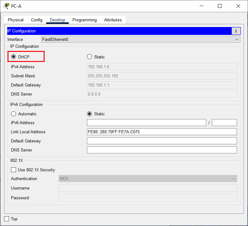
Step 4: Attempt to acquire an IP address from DHCP on PC-A
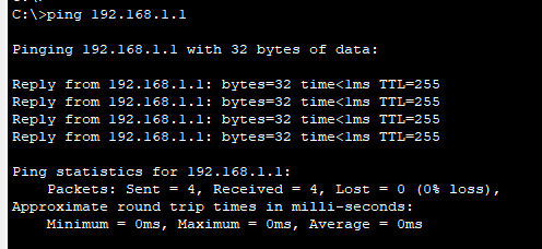
a. Open a command prompt on PC-A and issue the command ipconfig /renew.
b. Once the renewal process is complete, issue the command ipconfig to view the new IP information.
c. Test connectivity by pinging R1’s G0/0/1 interface IP address.

Part 3: Configure and verify a DHCP Relay on R2
In Part 3, you will configure R2 to relay DHCP requests from the local area network on interface G0/0/1 to the DHCP server (R1).
Step 1: Configure R2 as a DHCP relay agent for the LAN on G0/0/1
a. Configure the ip helper-address command on G0/0/1 specifying R1’s G0/0/0 IP address.
R2(config)# interface g0/0/1
R2(config-if)# ip helper-address 10.0.0.1
b. Save your configuration.
R2(config-if)# end
R2# wr
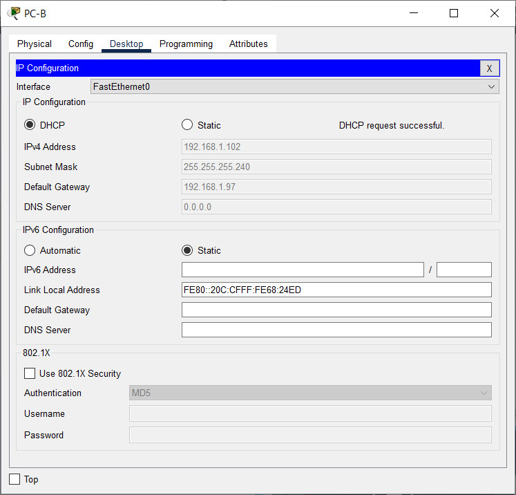
Step 2: Attempt to acquire an IP address from DHCP on PC-B
a. Open a command prompt on PC-B and issue the command ipconfig /renew.
b. Once the renewal process is complete, issue the command ipconfig to view the new IP information.
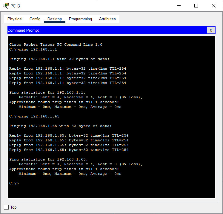
c. Test connectivity by pinging R1’s G0/0/1 interface IP address.

d. Issue the show ip dhcp binding on R1 to verify DHCP bindings.
e. Issue the show ip dhcp server statistics on R1 and R2 to verify DHCP messages.
Device Configs – Final
Switch S1
S1# show run
Building configuration...

Current configuration : 3194 bytes
!
version 15.2
no service pad
service timestamps debug datetime msec
service timestamps log datetime msec
service password-encryption
!
hostname S1
!
boot-start-marker
boot-end-marker
!
enable secret 5 $1$b/Df$nDTHDMqOPLb0hgz.shRjH.
!
no aaa new-model
system mtu routing 1500
!
!
no ip domain-lookup
!
!
spanning-tree mode rapid-pvst
spanning-tree extend system-id
!
vlan internal allocation policy ascending
!
!
interface FastEthernet0/1
 switchport access vlan 999
 switchport mode access
 shutdown
!
interface FastEthernet0/2
 switchport access vlan 999
 switchport mode access
 shutdown
!
interface FastEthernet0/3
 switchport access vlan 999
 switchport mode access
 shutdown
!
interface FastEthernet0/4
 switchport access vlan 999
 switchport mode access
 shutdown
!
interface FastEthernet0/5
 switchport trunk allowed vlan 100,200,1000
 switchport trunk native vlan 1000
 switchport mode trunk
!
interface FastEthernet0/6
 switchport access vlan 100
 switchport mode access
!
interface FastEthernet0/7
 switchport access vlan 999
 switchport mode access
 shutdown
!
interface FastEthernet0/8
 switchport access vlan 999
 switchport mode access
 shutdown
!
interface FastEthernet0/9
 switchport access vlan 999
 switchport mode access
 shutdown
!
interface FastEthernet0/10
 switchport access vlan 999
 switchport mode access
 shutdown
!
interface FastEthernet0/11
 switchport access vlan 999
 switchport mode access
 shutdown
!
interface FastEthernet0/12
 switchport access vlan 999
 switchport mode access
 shutdown
!
interface FastEthernet0/13
 switchport access vlan 999
 switchport mode access
 shutdown
!
interface FastEthernet0/14
 switchport access vlan 999
 switchport mode access
 shutdown
!
interface FastEthernet0/15
 switchport access vlan 999
 switchport mode access
 shutdown
!
interface FastEthernet0/16
 switchport access vlan 999
 switchport mode access
 shutdown
!
interface FastEthernet0/17
 switchport access vlan 999
 switchport mode access
 shutdown
!
interface FastEthernet0/18
 switchport access vlan 999
 switchport mode access
 shutdown
!
interface FastEthernet0/19
 switchport access vlan 999
 switchport mode access
 shutdown
!
interface FastEthernet0/20
 switchport access vlan 999
 switchport mode access
 shutdown
!
interface FastEthernet0/21
 switchport access vlan 999
 switchport mode access
 shutdown
!
interface FastEthernet0/22
 switchport access vlan 999
 switchport mode access
 shutdown
!
interface FastEthernet0/23
 switchport access vlan 999
 switchport mode access
 shutdown
!
interface FastEthernet0/24
 switchport access vlan 999
 switchport mode access
 shutdown
!
interface GigabitEthernet0/1
 switchport access vlan 999
 switchport mode access
 shutdown
!
interface GigabitEthernet0/2
 switchport access vlan 999
 switchport mode access
 shutdown
!
interface Vlan1
 no ip address
 shutdown
!
interface Vlan200
 ip address 192.168.1.66 255.255.255.224

ip default-gateway 192.168.1.65
!
ip http server
ip http secure-server
!
banner motd ^C Authorized Users Only! ^C
!
line con 0
 password 7 060506324F41
 login
line vty 0 4
 password 7 060506324F41
 login
line vty 5 15
 login
!
vlan 100
 name Clients
vlan 200
 name Management
vlan 999
 name Parking_Lot
vlan 1000
 name Native
exit
!
end
Switch S2
S2# show run
Building configuration...

Current configuration : 2323 bytes
!
version 15.2
no service pad
service timestamps debug datetime msec
service timestamps log datetime msec
service password-encryption
!
hostname S2
!
boot-start-marker
boot-end-marker
!
enable secret 5 $1$86v.$3mG1aMq7hcn2P0ZDNa2o5.
!
no aaa new-model
system mtu routing 1500
!
!
no ip domain-lookup
!
!
spanning-tree mode rapid-pvst
spanning-tree extend system-id
!
vlan internal allocation policy ascending
!
!
interface FastEthernet0/1
 switchport mode access
 shutdown
!
interface FastEthernet0/2
 switchport mode access
 shutdown
!
interface FastEthernet0/3
 switchport mode access
 shutdown
!
interface FastEthernet0/4
 switchport mode access
 shutdown
!
interface FastEthernet0/5
!
interface FastEthernet0/6
 switchport mode access
 shutdown
!
interface FastEthernet0/7
 switchport mode access
 shutdown
!
interface FastEthernet0/8
 switchport mode access
 shutdown
!
interface FastEthernet0/9
 switchport mode access
 shutdown
!
interface FastEthernet0/10
 switchport mode access
 shutdown
!
interface FastEthernet0/11
 switchport mode access
 shutdown
!
interface FastEthernet0/12
 switchport mode access
 shutdown
!
interface FastEthernet0/13
 switchport mode access
 shutdown
!
interface FastEthernet0/14
 switchport mode access
 shutdown
!
interface FastEthernet0/15
 switchport mode access
 shutdown
!
interface FastEthernet0/16
 switchport mode access
 shutdown
!
interface FastEthernet0/17
 switchport mode access
 shutdown
!
interface FastEthernet0/18
!
interface FastEthernet0/19
 switchport mode access
 shutdown
!
interface FastEthernet0/20
 switchport mode access
 shutdown
!
interface FastEthernet0/21
 switchport mode access
 shutdown
!
interface FastEthernet0/22
 switchport mode access
 shutdown
!
interface FastEthernet0/23
 switchport mode access
 shutdown
!
interface FastEthernet0/24
 switchport mode access
 shutdown
!
interface GigabitEthernet0/1
 switchport mode access
 shutdown
!
interface GigabitEthernet0/2
 switchport mode access
 shutdown
!
interface Vlan1
 ip address 192.168.1.98 255.255.255.240
!
ip default-gateway 192.168.1.97
ip http server
ip http secure-server
!
banner motd ^C Authorized Users Only! ^C
!
line con 0
 password 7 045802150C2E
 login
line vty 0 4
 password 7 045802150C2E
 login
line vty 5 15
 login
!
end
Router R1
R1# show run
Building configuration...


Current configuration : 2225 bytes
!
version 16.9
service timestamps debug datetime msec
service timestamps log datetime msec
service password-encryption
no platform punt-keepalive disable-kernel-core
!
hostname R1
!
boot-start-marker
boot-end-marker
!
!
vrf definition Mgmt-intf
 !
 address-family ipv4
 exit-address-family
 !
 address-family ipv6
 exit-address-family
!
enable secret 5 $1$lzpq$ribRztM6WUv/dsnQ7x24a/
!
no aaa new-model
!
!
no ip domain-lookup
ip dhcp excluded-address 192.168.1.1 192.168.1.5
ip dhcp excluded-address 192.168.1.97 192.168.1.101
!
ip dhcp pool R1_Client_LAN
 network 192.168.1.0 255.255.255.192
 domain-name ccna-lab.com
 default-router 192.168.1.1
 lease 2 12 30
!
ip dhcp pool R2_Client_LAN
 network 192.168.1.96 255.255.255.240
 default-router 192.168.1.97
 domain-name ccna-lab.com
 lease 2 12 30
!
!
subscriber templating
!
multilink bundle-name authenticated
!
spanning-tree extend system-id
!
!
redundancy
 mode none
!
!
interface GigabitEthernet0/0/0
ip address 10.0.0.1 255.255.255.252
 negotiation auto
!
interface GigabitEthernet0/0/1
 no ip address
 negotiation auto
!
interface GigabitEthernet0/0/1.100
 description Connected to Client Network
 encapsulation dot1Q 100
 ip address 192.168.1.1 255.255.255.192
!
interface GigabitEthernet0/0/1.200
 description Connected to Management Network
 encapsulation dot1Q 200
 ip address 192.168.1.65 255.255.255.224
!
interface GigabitEthernet0/0/1.1000
 description Connected to Native VLAN
 encapsulation dot1Q 1000 native
!
interface Serial0/1/0
!
interface Serial0/1/1
!
interface GigabitEthernet0
 vrf forwarding Mgmt-intf
 no ip address
 shutdown
 negotiation auto
!
ip forward-protocol nd
no ip http server
no ip http secure-server
ip tftp source-interface GigabitEthernet0
ip route 0.0.0.0 0.0.0.0 10.0.0.2
!
!
control-plane
!
banner motd ^C Authorized Users Only! ^C
!
line con 0
 password 7 01100F175804
 login
 stopbits 1
line aux 0
 stopbits 1
line vty 0 4
 password 7 02050D480809
 login
!
end
Router R2
R2# show run
Building configuration...

Current configuration : 1501 bytes
!
version 16.9
service timestamps debug datetime msec
service timestamps log datetime msec
service password-encryption
no platform punt-keepalive disable-kernel-core
!
hostname R2
!
boot-start-marker
boot-end-marker
!
!
vrf definition Mgmt-intf
 !
 address-family ipv4
 exit-address-family
 !
 address-family ipv6
 exit-address-family
!
enable secret 5 $1$swCy$LDg9k0nMAN5Cxn9EcPNSx1
!
no aaa new-model
!
no ip domain-lookup
!
!
subscriber templating
!
multilink bundle-name authenticated
!
spanning-tree extend system-id
!
!
redundancy
 mode none
!
!
interface GigabitEthernet0/0/0
ip address 10.0.0.2 255.255.255.252
 negotiation auto
!
interface GigabitEthernet0/0/1
 ip address 192.168.1.97 255.255.255.240
 ip helper-address 10.0.0.1
negotiation auto
!
interface Serial0/1/0
!
interface Serial0/1/1
!
interface GigabitEthernet0
 vrf forwarding Mgmt-intf
 no ip address
 shutdown
 negotiation auto
!
ip forward-protocol nd
no ip http server
no ip http secure-server
ip tftp source-interface GigabitEthernet0
ip route 0.0.0.0 0.0.0.0 10.0.0.1
!
!
control-plane
!
banner motd ^C Authorized Users Only! ^C
!
line con 0
 password 7 05080F1C2243
 login
 stopbits 1
line aux 0
 stopbits 1
line vty 0 4
 password 7 104D000A0618
 login
!
end


good
for those struggling like me, packet tracer does not support some dhcp commands and you either need to negotiate this with your professor or use GNS3 to perform this assignment instead.
I can not download PDF & PKT file , could you help sir ?
where is my download????!!
Great!