3.0 Introduction
3.0.1 Why should I take this module?
Welcome to VLANs!
Imagine that you are in charge of a very large conference. There are people from all over who share a common interest and some who also have special expertise. Imagine if each expert who wanted to present their information to a smaller audience had to do that in the same large room with all the other experts and their smaller audiences. Nobody would be able to hear anything. You would have to find separate rooms for all the experts and their smaller audiences. The Virtual LAN (VLAN) does something similar in a network. VLANs are created at Layer 2 to reducing or eliminate broadcast traffic. VLANs are how you break up your network into smaller networks, so that the devices and people within a single VLAN are communicating with each other and not having to manage traffic from other networks. The network administrator can organize VLANs by location, who is using them, the type of device, or whatever category is needed. You know you want to learn how to do this, so don’t wait!
3.0.2 What will I learn to do in this module?
Module Title: VLANs
Module Objective: Implement VLANs and trunking in a switched network.
| Topic Title | Topic Objective |
|---|---|
| Overview of VLANs | Explain the purpose of VLANs in a switched network |
| VLANs in a Multi-Switched Environment | Explain how a switch forwards frames based on VLAN configuration in a multi-switch environment. |
| VLAN Configuration | Configure a switch port to be assigned to a VLAN based on requirements. |
| VLAN Trunks | Configure a trunk port on a LAN switch. |
| Dynamic Trunking Protocol | Configure Dynamic Trunking Protocol (DTP). |
3.1 Overview of VLANs
3.1.1 VLAN Definitions
Of course organizing your network into smaller networks is not as simple as separating screws and putting them into jars. But it will make your network easier to manage. Virtual LANs (VLANs) provide segmentation and organizational flexibility in a switched network. A group of devices within a VLAN communicate as if each device was attached to the same cable. VLANs are based on logical connections, instead of physical connections.
As shown in the figure, VLANs in a switched network enable users in various departments (i.e., IT, HR, and Sales) to connect to the same network regardless of the physical switch being used or location in a campus LAN.
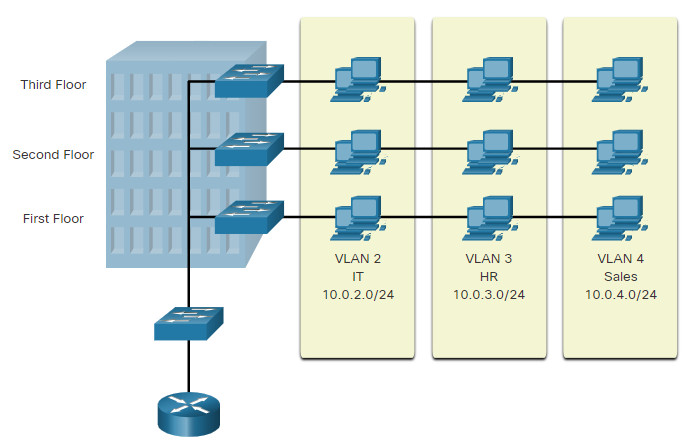
VLANs allow an administrator to segment networks based on factors such as function, team, or application, without regard for the physical location of the users or devices. Each VLAN is considered a separate logical network. Devices within a VLAN act as if they are in their own independent network, even if they share a common infrastructure with other VLANs. Any switch port can belong to a VLAN.
Unicast, broadcast, and multicast packets are forwarded and flooded only to end devices within the VLAN where the packets are sourced. Packets destined for devices that do not belong to the VLAN must be forwarded through a device that supports routing.
Multiple IP subnets can exist on a switched network, without the use of multiple VLANs. However, the devices will be in the same Layer 2 broadcast domain. This means that any Layer 2 broadcasts, such as an ARP request, will be received by all devices on the switched network, even by those not intended to receive the broadcast.
A VLAN creates a logical broadcast domain that can span multiple physical LAN segments. VLANs improve network performance by separating large broadcast domains into smaller ones. If a device in one VLAN sends a broadcast Ethernet frame, all devices in the VLAN receive the frame, but devices in other VLANs do not.
Using VLANs, network administrators can implement access and security policies according to specific groupings of users. Each switch port can be assigned to only one VLAN (except for a port connected to an IP phone or to another switch).
3.1.2 Benefits of a VLAN Design
Each VLAN in a switched network corresponds to an IP network. Therefore, VLAN design must take into consideration the implementation of a hierarchical network-addressing scheme. Hierarchical network addressing means that IP network numbers are applied to network segments or VLANs in a way that takes the network as a whole into consideration. Blocks of contiguous network addresses are reserved for and configured on devices in a specific area of the network, as shown in the figure.
The table lists the benefits of designing a network with VLANs.
| Benefit | Description |
|---|---|
| Smaller broadcast domains |
|
| Improved security |
|
| Improved IT efficiency |
|
| Reduced cost | VLANs reduce the need for expensive network upgrades and use the existing bandwidth and uplinks more efficiently, resulting in cost savings. |
| Better performance | Smaller broadcast domains reduce unnecessary traffic on the network and improve performance. |
| Simpler project and application management |
|
3.1.3 Types of VLANs
VLANs are used for different reasons in modern networks. Some VLAN types are defined by traffic classes. Other types of VLANs are defined by the specific function that they serve.
Click each VLAN type for more information.
3.1.4 Packet Tracer – Who Hears the Broadcast?
In this Packet Tracer activity, you will complete the following objectives:
- Part 1: Observe Broadcast Traffic in a VLAN Implementation
- Part 2: Complete Review Questions
3.1.4 Packet Tracer – Who Hears the Broadcast?
3.2 VLANs in a Multi-Switched Environment
3.2.1 Defining VLAN Trunks
VLANs would not be very useful without VLAN trunks. VLAN trunks allow all VLAN traffic to propagate between switches. This enables devices connected to different switches but in the same VLAN to communicate without going through a router.
A trunk is a point-to-point link between two network devices that carries more than one VLAN. A VLAN trunk extends VLANs across an entire network. Cisco supports IEEE 802.1Q for coordinating trunks on Fast Ethernet, Gigabit Ethernet, and 10-Gigabit Ethernet interfaces.
A VLAN trunk does not belong to a specific VLAN. Instead, it is a conduit for multiple VLANs between switches and routers. A trunk could also be used between a network device and server or another device that is equipped with an appropriate 802.1Q-capable NIC. By default, on a Cisco Catalyst switch, all VLANs are supported on a trunk port.
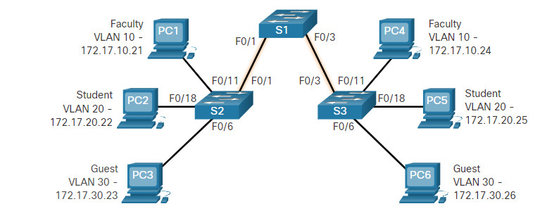
In the figure, the highlighted links between switches S1 and S2, and S1 and S3 are configured to transmit traffic coming from VLANs 10, 20, 30, and 99 (i.e., native VLAN) across the network. This network could not function without VLAN trunks.
3.2.2 Network without VLANs
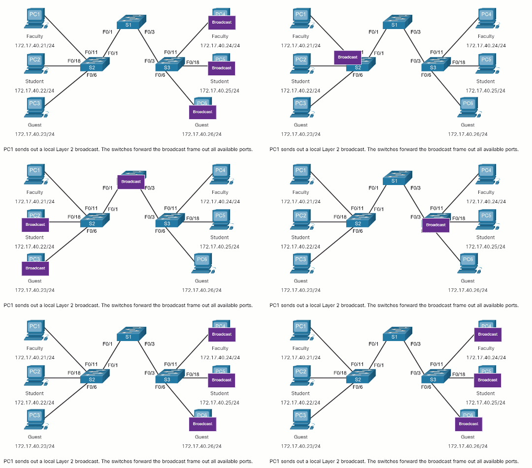
When a switch receives a broadcast frame on one of its ports, it forwards the frame out all other ports except the port where the broadcast was received. In the animation, the entire network is configured in the same subnet (172.17.40.0/24) and no VLANs are configured. As a result, when the faculty computer (PC1) sends out a broadcast frame, switch S2 sends that broadcast frame out all of its ports. Eventually the entire network receives the broadcast because the network is one broadcast domain.
3.2.3 Network with VLANs
Click Play in the animation to see that the same network has now been segmented using two VLANs. Faculty devices are assigned to VLAN 10 and student devices are assigned to VLAN 20. When a broadcast frame is sent from the faculty computer, PC1, to switch S2, the switch forwards that broadcast frame only to those switch ports configured to support VLAN 10.
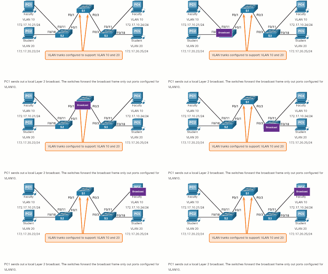
The ports that comprise the connection between switches S2 and S1 (ports F0/1), and between S1 and S3 (ports F0/3) are trunks and have been configured to support all the VLANs in the network.
When S1 receives the broadcast frame on port F0/1, S1 forwards that broadcast frame out of the only other port configured to support VLAN 10, which is port F0/3. When S3 receives the broadcast frame on port F0/3, it forwards that broadcast frame out the only other port configured to support VLAN 10, which is port F0/11. The broadcast frame arrives at the only other computer in the network configured in VLAN 10, which is faculty computer PC4.
When VLANs are implemented on a switch, the transmission of unicast, multicast, and broadcast traffic from a host in a particular VLAN are restricted to the devices that are in that VLAN.
3.2.4 VLAN Identification with a Tag
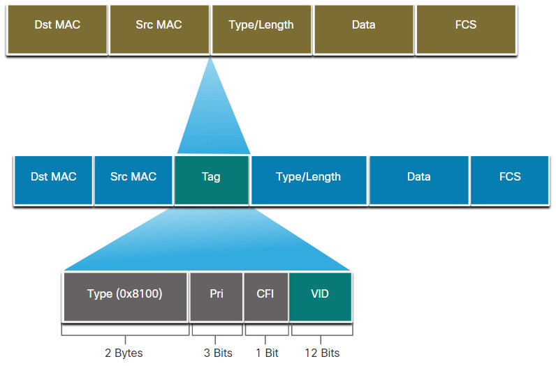
The standard Ethernet frame header does not contain information about the VLAN to which the frame belongs. Therefore, when Ethernet frames are placed on a trunk, information about the VLANs to which they belong must be added. This process, called tagging, is accomplished by using the IEEE 802.1Q header, specified in the IEEE 802.1Q standard. The 802.1Q header includes a 4-byte tag inserted within the original Ethernet frame header, specifying the VLAN to which the frame belongs.
When the switch receives a frame on a port configured in access mode and assigned a VLAN, the switch inserts a VLAN tag in the frame header, recalculates the Frame Check Sequence (FCS), and sends the tagged frame out of a trunk port.
VLAN Tag Field Details
As shown in the figure, the VLAN tag control information field consists of a Type field, a Priority field, a Canonical Format Identifier field, and VLAN ID field:
- Type – A 2-byte value called the tag protocol ID (TPID) value. For Ethernet, it is set to hexadecimal 0x8100.
- User priority – A 3-bit value that supports level or service implementation.
- Canonical Format Identifier (CFI) – A 1-bit identifier that enables Token Ring frames to be carried across Ethernet links.
- VLAN ID (VID) – A 12-bit VLAN identification number that supports up to 4096 VLAN IDs.
After the switch inserts the tag control information fields, it recalculates the FCS values and inserts the new FCS into the frame.
3.2.5 Native VLANs and 802.1Q Tagging
The IEEE 802.1Q standard specifies a native VLAN for trunk links, which defaults to VLAN 1. When an untagged frame arrives on a trunk port it is assigned to the native VLAN. Management frames that are sent between switches is an example of traffic that is typically untagged. If the link between two switches is a trunk, the switch sends the untagged traffic on the native VLAN.
Tagged Frames on the Native VLAN
Some devices that support trunking add a VLAN tag to native VLAN traffic. Control traffic sent on the native VLAN should not be tagged. If an 802.1Q trunk port receives a tagged frame with the VLAN ID that is the same as the native VLAN, it drops the frame. Consequently, when configuring a switch port on a Cisco switch, configure devices so that they do not send tagged frames on the native VLAN. Devices from other vendors that support tagged frames on the native VLAN include IP phones, servers, routers, and non-Cisco switches.
Untagged Frames on the Native VLAN
When a Cisco switch trunk port receives untagged frames (which are unusual in a well-designed network), it forwards those frames to the native VLAN. If there are no devices associated with the native VLAN (which is not unusual) and there are no other trunk ports (which is not unusual), then the frame is dropped. The default native VLAN is VLAN 1. When configuring an 802.1Q trunk port, a default Port VLAN ID (PVID) is assigned the value of the native VLAN ID. All untagged traffic coming in or out of the 802.1Q port is forwarded based on the PVID value. For example, if VLAN 99 is configured as the native VLAN, the PVID is 99 and all untagged traffic is forwarded to VLAN 99. If the native VLAN has not been reconfigured, the PVID value is set to VLAN 1.
In the figure, PC1 is connected by a hub to an 802.1Q trunk link.
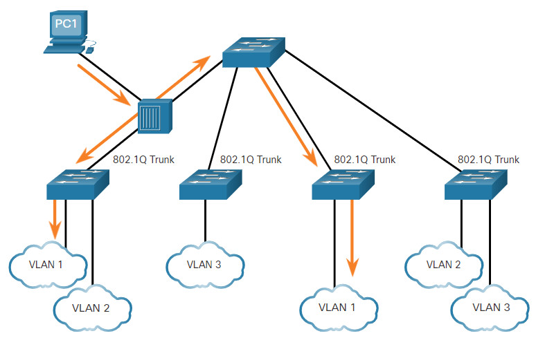
PC1 sends untagged traffic, which the switches associate with the native VLAN configured on the trunk ports, and forward accordingly. Tagged traffic on the trunk received by PC1 is dropped. This scenario reflects poor network design for several reasons: it uses a hub, it has a host connected to a trunk link, and it implies that the switches have access ports assigned to the native VLAN. It also illustrates the motivation for the IEEE 802.1Q specification for native VLANs as a means of handling legacy scenarios.
3.2.6 Voice VLAN Tagging
A separate voice VLAN is required to support VoIP. This enables quality of service (QoS) and security policies to be applied to voice traffic.
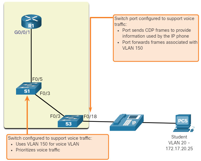
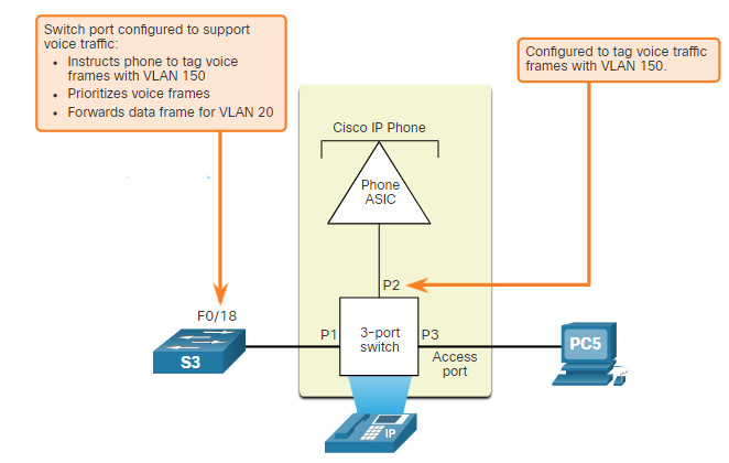
A Cisco IP phone connects directly to a switch port. An IP host can connect to the IP phone to gain network connectivity as well. The access port connected to the Cisco IP phone can be configured to use two separate VLANs. One VLAN is for voice traffic and the other is a data VLAN to support the host traffic. The link between the switch and the IP phone simulates a trunk link to carry both voice VLAN traffic and data VLAN traffic.
Specifically, the Cisco IP Phone contains an integrated three-port 10/100 switch. The ports provide dedicated connections to the following devices:
- Port 1 connects to the switch or other VoIP device.
- Port 2 is an internal 10/100 interface that carries the IP phone traffic.
- Port 3 (access port) connects to a PC or other device.
The switch access port sends CDP packets instructing the attached IP phone to send voice traffic in one of three ways. The method used varies based on the type of traffic:
- Voice VLAN traffic must be tagged with an appropriate Layer 2 class of service (CoS) priority value
- Access VLAN traffic can also be tagged with a Layer 2 CoS priority value
- Access VLAN is not tagged (no Layer 2 CoS priority value)
In the figure, the student computer PC5 is attached to a Cisco IP phone, and the phone is attached to switch S3. VLAN 150 is designed to carry voice traffic, while PC5 is in VLAN 20, which is used for student data.
3.2.7 Voice VLAN Verification Example
The example output for the show interface fa0/18 switchport command is shown. The highlighted areas in the sample output show the F0/18 interface configured with a VLAN that is configured for data (VLAN 20), and a VLAN configured for voice (VLAN 150).
S1# show interfaces fa0/18 switchport Name: Fa0/18 Switchport: Enabled Administrative Mode: static access Operational Mode: static access Administrative Trunking Encapsulation: negotiate Operational Trunking Encapsulation: native Negotiation of Trunking: Off Access Mode VLAN: 20 (student) Trunking Native Mode VLAN: 1 (default) Administrative Native VLAN tagging: enabled Voice VLAN: 150 (voice)
3.2.8 Packet Tracer – Investigate a VLAN Implementation
In this activity, you will observe how broadcast traffic is forwarded by the switches when VLANs are configured and when VLANs are not configured.
3.2.8 Packet Tracer – Investigate a VLAN Implementation
3.3 VLAN Configuration
3.3.1 VLAN Ranges on Catalyst Switches
Creating VLANs, like most other aspects of networking, is a matter of entering the appropriate commands. This topic details how to configure and verify different types of VLANs.
Different Cisco Catalyst switches support various numbers of VLANs. The number of supported VLANs is large enough to accommodate the needs of most organizations. For example, the Catalyst 2960 and 3650 Series switches support over 4,000 VLANs. Normal range VLANs on these switches are numbered 1 to 1,005 and extended range VLANs are numbered 1,006 to 4,094. The figure illustrates the default VLANs on a Catalyst 2960 switch running Cisco IOS Release 15.x.
Switch# show vlan brief
VLAN Name              Status   Ports
---- ----------------- -------  --------------------
1    default           active   Fa0/1, Fa0/2, Fa0/3, Fa0/4
                                Fa0/5, Fa0/6, Fa0/7, Fa0/8
                                Fa0/9, Fa0/10, Fa0/11, Fa0/12
                                Fa0/13, Fa0/14, Fa0/15, Fa0/16
                                Fa0/17, Fa0/18, Fa0/19, Fa0/20
                                Fa0/21, Fa0/22, Fa0/23, Fa0/24
                                Gi0/1, Gi0/2
1002 fddi-default                     act/unsup
1003 token-ring-default               act/unsup
1004 fddinet-default                  act/unsup
1005 trnet-default                    act/unsup
Normal Range VLANs
The following are characteristics of normal range VLANs:
- They are used in all small- and medium-sized business and enterprise networks.
- They are identified by a VLAN ID between 1 and 1005.
- IDs 1002 through 1005 are reserved for legacy network technologies (i.e., Token Ring and Fiber Distributed Data Interface).
- IDs 1 and 1002 to 1005 are automatically created and cannot be removed.
- Configurations are stored in the switch flash memory in a VLAN database file called vlan.dat.
- When configured, VLAN trunking protocol (VTP), helps synchronize the VLAN database between switches.
Extended Range VLANs
The following are characteristics of extended range VLANs:
- They are used by service providers to service multiple customers and by global enterprises large enough to need extended range VLAN IDs.
- They are identified by a VLAN ID between 1006 and 4094.
- Configurations are saved, by default, in the running configuration.
- They support fewer VLAN features than normal range VLANs.
- Requires VTP transparent mode configuration to support extended range VLANs.
Note: 4096 is the upper boundary for the number of VLANs available on Catalyst switches, because there are 12 bits in the VLAN ID field of the IEEE 802.1Q header.
3.3.2 VLAN Creation Commands
When configuring normal range VLANs, the configuration details are stored in flash memory on the switch in a file called vlan.dat. Flash memory is persistent and does not require the copy running-config startup-config command. However, because other details are often configured on a Cisco switch at the same time that VLANs are created, it is good practice to save running configuration changes to the startup configuration.
The table displays the Cisco IOS command syntax used to add a VLAN to a switch and give it a name. Naming each VLAN is considered a best practice in switch configuration.
| Task | IOS Command |
|---|---|
| Enter global configuration mode. | Switch# configure terminal |
| Create a VLAN with a valid ID number. | Switch(config)# vlan vlan-id |
| Specify a unique name to identify the VLAN. | Switch(config-vlan)# name vlan-name |
| Return to the privileged EXEC mode. | Switch(config-vlan)# end |
3.3.3 VLAN Creation Example
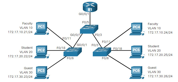
In the topology, the student computer (PC2) has not been associated with a VLAN yet, but it does have an IP address of 172.17.20.22, which belongs to VLAN 20.
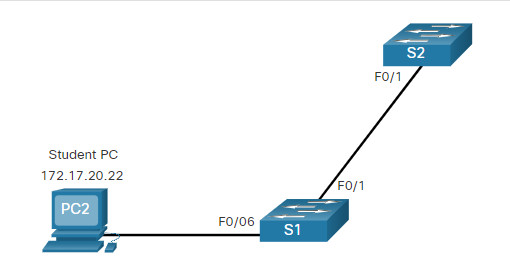
The example shows how the student VLAN (VLAN 20) is configured on switch S1.
S1# configure terminal
S1(config)# vlan 20
S1(config-vlan)# name student
S1(config-vlan)# end
Note: In addition to entering a single VLAN ID, a series of VLAN IDs can be entered separated by commas, or a range of VLAN IDs separated by hyphens using the vlan vlan-id command. For example, entering the vlan 100,102,105-107 global configuration command would create VLANs 100, 102, 105, 106, and 107.
Note: In addition to entering a single VLAN ID, a series of VLAN IDs can be entered separated by commas, or a range of VLAN IDs separated by hyphens using the vlan vlan-id command. For example, entering the vlan 100,102,105-107 global configuration command would create VLANs 100, 102, 105, 106, and 107.
3.3.4 VLAN Port Assignment Commands
After creating a VLAN, the next step is to assign ports to the VLAN.
The table displays the syntax for defining a port to be an access port and assigning it to a VLAN. The switchport mode access command is optional, but strongly recommended as a security best practice. With this command, the interface changes to permanent access mode.
| Task | IOS Command |
|---|---|
| Enter global configuration mode. | Switch# configure terminal |
| Enter interface configuration mode. | Switch(config)# interface interface-id |
| Set the port to access mode. | Switch(config-if)# switchport mode access |
| Assign the port to a VLAN. | Switch(config-if)# switchport access vlan vlan-id |
| Return to the privileged EXEC mode. | Switch(config-if)# end |
Note: Use the interface range command to simultaneously configure multiple interfaces.
3.3.5 VLAN Port Assignment Example
In the figure, port F0/6 on switch S1 is configured as an access port and assigned to VLAN 20. Any device connected to that port will be associated with VLAN 20. Therefore, in our example, PC2 is in VLAN 20.
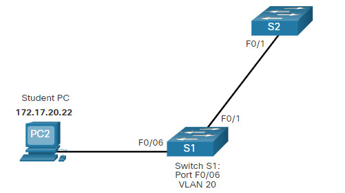
The example shows the configuration for S1 to assign F0/6 to VLAN 20.
S1# configure terminal
S1(config)# interface fa0/6
S1(config-if)# switchport mode access
S1(config-if)# switchport access vlan 20
S1(config-if)# end
VLANs are configured on the switch port and not on the end device. PC2 is configured with an IPv4 address and subnet mask that is associated with the VLAN, which is configured on the switch port. In this example, it is VLAN 20. When VLAN 20 is configured on other switches, the network administrator must configure the other student computers to be in the same subnet as PC2 (172.17.20.0/24).
3.3.6 Data and Voice VLANs
An access port can belong to only one data VLAN at a time. However, a port can also be associated to a voice VLAN. For example, a port connected to an IP phone and an end device would be associated with two VLANs: one for voice and one for data.
Consider the topology in the figure. PC5 is connected to the Cisco IP phone, which in turn is connected to the FastEthernet 0/18 interface on S3. To implement this configuration, a data VLAN and a voice VLAN are created.
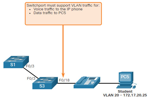
3.3.7 Data and Voice VLAN Example
Use the switchport voice vlan vlan-id interface configuration command to assign a voice VLAN to a port.
LANs supporting voice traffic typically also have quality of service (QoS) enabled. Voice traffic must be labeled as trusted as soon as it enters the network. Use the mls qos trust [cos | device cisco-phone | dscp | ip-precedence] interface configuration command to set the trusted state of an interface, and to indicate which fields of the packet are used to classify traffic.
The configuration in the example creates the two VLANs (i.e., VLAN 20 and VLAN 150) and then assigns the F0/18 interface of S3 as a switchport in VLAN 20. It also assigns voice traffic to VLAN 150 and enables QoS classification based on the class of service (CoS) assigned by the IP phone.
S3(config)# vlan 20
S3(config-vlan)# name student
S3(config-vlan)# vlan 150
S3(config-vlan)# name VOICE
S3(config-vlan)# exit
S3(config)# interface fa0/18
S3(config-if)# switchport mode access
S3(config-if)# switchport access vlan 20
S3(config-if)# mls qos trust cos
S3(config-if)# switchport voice vlan 150
S3(config-if)# end
S3#
Note: The implementation of QoS is beyond the scope of this course.
The switchport access vlan command forces the creation of a VLAN if it does not already exist on the switch. For example, VLAN 30 is not present in the show vlan brief output of the switch. If the switchport access vlan 30 command is entered on any interface with no previous configuration, then the switch displays the following:
% Access VLAN does not exist. Creating vlan 30
3.3.8 Verify VLAN Information
After a VLAN is configured, VLAN configurations can be validated using Cisco IOS show commands.
The show vlan command displays a list of all configured VLANs. The show vlan command can also be used with options. The complete syntax is show vlan [brief | id vlan-id | name vlan-name | summary].
The table describes the show vlan command options.
| Task | Command Option |
|---|---|
| Display VLAN name, status, and its ports one VLAN per line. | brief |
| Display information about the identified VLAN ID number. For vlan-id, the range is 1 to 4094. | id vlan-id |
| Display information about the identified VLAN name. The vlan-name is an ASCII string from 1 to 32 characters. | name vlan-name |
| Display VLAN summary information. | summary |
The show vlan summary command displays the count of all configured VLANs.
S1# show vlan summary
Number of existing VLANs              : 7
Number of existing VTP VLANs          : 7
Number of existing extended VLANS     : 0
Other useful commands are the show interfaces interface-id switchport and the show interfaces vlan vlan-id command. For example, the show interfaces fa0/18 switchport command can be used to confirm that the FastEthernet 0/18 port has been correctly assigned to data and voice VLANs.
S1# show interfaces fa0/18 switchport
Name: Fa0/18
Switchport: Enabled
Administrative Mode: static access
Operational Mode: static access
Administrative Trunking Encapsulation: dot1q
Operational Trunking Encapsulation: native
Negotiation of Trunking: Off
Access Mode VLAN: 20 (student)
Trunking Native Mode VLAN: 1 (default)
Voice VLAN: 150
Administrative private-vlan host-association: none
(Output omitted)
3.3.9 Change VLAN Port Membership
There are a number of ways to change VLAN port membership.
If the switch access port has been incorrectly assigned to a VLAN, then simply re-enter the switchport access vlan vlan-id interface configuration command with the correct VLAN ID. For instance, assume Fa0/18 was incorrectly configured to be on the default VLAN 1 instead of VLAN 20. To change the port to VLAN 20, simply enter switchport access vlan 20.
To change the membership of a port back to the default VLAN 1, use the no switchport access vlan interface configuration mode command as shown.
In the output for example, Fa0/18 is configured to be on the default VLAN 1 as confirmed by the show vlan brief command.
S1(config)# interface fa0/18
S1(config-if)# no switchport access vlan
S1(config-if)# end
S1#
S1# show vlan brief
VLAN Name                 Status    Ports
---- ------------------ --------- -------------------------------
1    default            active    Fa0/1, Fa0/2, Fa0/3, Fa0/4
                                  Fa0/5, Fa0/6, Fa0/7, Fa0/8
                                  Fa0/9, Fa0/10, Fa0/11, Fa0/12
                                  Fa0/13, Fa0/14, Fa0/15, Fa0/16
                                  Fa0/17, Fa0/18, Fa0/19, Fa0/20
                                  Fa0/21, Fa0/22, Fa0/23, Fa0/24
                                  Gi0/1, Gi0/2
20   student            active
1002 fddi-default       act/unsup
1003 token-ring-default act/unsup
1004 fddinet-default    act/unsup
1005 trnet-default      act/unsup
Notice that VLAN 20 is still active, even though no ports are assigned to it.
The show interfaces f0/18 switchport output can also be used to verify that the access VLAN for interface F0/18 has been reset to VLAN 1 as shown in the output.
S1# show interfaces fa0/18 switchport
Name: Fa0/18
Switchport: Enabled
Administrative Mode: static access
Operational Mode: static access
Administrative Trunking Encapsulation: negotiate
Operational Trunking Encapsulation: native
Negotiation of Trunking: Off
Access Mode VLAN: 1 (default)
Trunking Native Mode VLAN: 1 (default)
3.3.10 Delete VLANs
The no vlan vlan-id global configuration mode command is used to remove a VLAN from the switch vlan.dat file.
Caution: Before deleting a VLAN, reassign all member ports to a different VLAN first. Any ports that are not moved to an active VLAN are unable to communicate with other hosts after the VLAN is deleted and until they are assigned to an active VLAN.
The entire vlan.dat file can be deleted using the delete flash:vlan.dat privileged EXEC mode command. The abbreviated command version (delete vlan.dat) can be used if the vlan.dat file has not been moved from its default location. After issuing this command and reloading the switch, any previously configured VLANs are no longer present. This effectively places the switch into its factory default condition with regard to VLAN configurations.
Note: To restore a Catalyst switch to its factory default condition, unplug all cables except the console and power cable from the switch. Then enter the erase startup-config privileged EXEC mode command followed by the delete vlan.dat command.
3.3.11 Syntax Checker – VLAN Configuration
Complete the following steps to create a data VLAN:
-
- Enter global configuration mode.
-
- Create VLAN 20.
-
- Name the VLAN student.
- Return to privileged EXEC mode.
S1#configure terminal
Enter configuration commands, one per line. End with CNTL/Z.
S1(config)#vlan 20
S1(config-vlan)#name student
S1(config-vlan)#end
\*Mar 31, 08:55:14.5555: %SYS-5-CONFIG\_I: Configured from console by console
Display the brief VLAN information.

S1#show vlan brief
VLAN Name                             Status    Ports
---- -------------------------------- --------- -------------------------------
1    default                          active    Fa0/1, Fa0/2, Fa0/3, Fa0/4
                                                Fa0/5, Fa0/6, Fa0/7, Fa0/8
                                                Fa0/9, Fa0/10, Fa0/11, Fa0/12
                                                Fa0/13, Fa0/14, Fa0/15, Fa0/16
                                                Fa0/17, Fa0/18, Fa0/19, Fa0/20
                                                Fa0/21, Fa0/22, Fa0/23, Fa0/24
                                                Gi0/1, Gi0/2
20   student                          active
1002 fddi-default                     act/unsup
1003 token-ring-default               act/unsup
1004 fddinet-default                  act/unsup
1005 trnet-default                    act/unsup

Complete the following steps to create a voice VLAN:
-
- Enter global configuration mode.
-
- Create VLAN 150.
-
- Name the VLAN VOICE.
- Return to global configuration mode.
S1#configure terminal
S1(config)#vlan 150
S1(config-vlan)#name VOICE
S1(config-vlan)#exit

Complete the following steps to assign the data and voice VLANs to a port:
-
- Enter interface configuration mode. Use fa0/18 as the interface designation.
-
- Configure the port as an access port.
-
- Assign the data VLAN 20 to the port.
-
- Enable QoS settings with the mls qos trust cos command.
-
- Assign the voice VLAN 150 to the port.
- Return to privileged EXEC mode.
S1(config)#interface fa0/18
S1(config-if)#switchport mode access
S1(config-if)#switchport access vlan 20
S1(config-if)#mls qos trust cos
S1(config-if)#switchport voice vlan 150
S1(config-if)#end

Display the brief vlan information.

S1#show vlan brief
LAN Name                             Status    Ports
---- -------------------------------- --------- -------------------------------
1    default                          active    Fa0/1, Fa0/2, Fa0/3, Fa0/4
                                                Fa0/5, Fa0/6, Fa0/7, Fa0/8
                                                Fa0/9, Fa0/10, Fa0/11, Fa0/12
                                                Fa0/13, Fa0/14, Fa0/15, Fa0/16
                                                Fa0/17, Fa0/19, Fa0/20, Fa0/21
                                                Fa0/22, Fa0/23, Fa0/24, Gi0/1
                                                Gi0/2
20   student                          active    Fa0/18
150  VOICE                            active    Fa0/18
1002 fddi-default                     act/unsup
1003 token-ring-default               act/unsup
1004 fddinet-default                  act/unsup
1005 trnet-default                    act/unsup

Complete the following steps to delete and verify a deleted VLAN on a port:
-
- Enter global configuration mode.
-
- Enter interface configuration mode. Use fa0/18 as the interface designation.
-
- Remove the data VLAN from the port.
- Use the do form of the command to display brief VLAN information.
S1#configure terminal
S1(config)#interface fa0/18
S1(config-if)#no switchport access vlan
S1(config-if)#do show vlan brief
VLAN Name                             Status    Ports
---- -------------------------------- --------- -------------------------------
1    default                          active    Fa0/1, Fa0/2, Fa0/3, Fa0/4
                                                Fa0/5, Fa0/6, Fa0/7, Fa0/8
                                                Fa0/9, Fa0/10, Fa0/11, Fa0/12
                                                Fa0/13, Fa0/14, Fa0/15, Fa0/16
                                                Fa0/17, Fa0/18, Fa0/19, Fa0/20
                                                Fa0/21, Fa0/22, Fa0/23, Fa0/24
                                                Gi0/1, Gi0/2
20   student                          active
150  VOICE                            active    Fa0/18
1002 fddi-default                     act/unsup
1003 token-ring-default               act/unsup
1004 fddinet-default                  act/unsup
1005 trnet-default                    act/unsup

Complete the following steps to assign VLAN 20 to another interface.
-
- Enter interface configuration mode. Use fa0/11 as the interface designation.
-
- Assign VLAN 20 to the port.
- Return to privileged EXEC mode.
S1(config-if)#interface fa0/11
S1(config-if)#switchport mode access
S1(config-if)#switchport access vlan 20
S1(config-if)#end

Display the brief VLAN information.
S1#show vlan brief
LAN Name                             Status    Ports
---- -------------------------------- --------- -------------------------------
1    default                          active    Fa0/1, Fa0/2, Fa0/3, Fa0/4
                                                Fa0/5, Fa0/6, Fa0/7, Fa0/8
                                                Fa0/9, Fa0/10, Fa0/12, Fa0/13
                                                Fa0/14, Fa0/15, Fa0/16, Fa0/17
                                                Fa0/19, Fa0/20, Fa0/21, Fa0/22
                                                Fa0/23, Fa0/24, Gig0/1, Gig0/2
20   student                          active    Fa0/11, Fa0/18
150  VOICE                            active    Fa0/18
1002 fddi-default                     act/unsup
1003 token-ring-default               act/unsup
1004 fddinet-default                  act/unsup
1005 trnet-default                    act/unsup

Display the VLAN information specifically for the student VLAN.
S1#show vlan name student
VLAN Name                             Status    Ports
---- -------------------------------- --------- -------------------------------
20   student                          active    Fa0/11, Fa0/18
VLAN Type  SAID       MTU   Parent RingNo BridgeNo Stp  BrdgMode Trans1 Trans2
---- ----- ---------- ----- ------ ------ -------- ---- -------- ------ ------
20   enet  100020     1500  -      -      -        -    -        0      0
Display summary information for VLANs

S1#show vlan summary
Number of existing VLANs : 7
Number of existing VTP VLANs : 7
Number of existing extended VLANS : 0

Display the interface information for VLAN 20.
S1#show interfaces vlan 20
Vlan20 is up, line protocol is up
  Hardware is CPU Interface, address is 0007.ec74.61d3 (bia 0007.ec74.61d3)
  MTU 1500 bytes, BW 100000 Kbit, DLY 1000000 usec,
     reliability 255/255, txload 1/255, rxload 1/255
  Encapsulation ARPA, loopback not set
  ARP type: ARPA, ARP Timeout 04:00:00
  Last input 21:40:21, output never, output hang never
  Last clearing of "show interface" counters never
  Input queue: 0/75/0/0 (size/max/drops/flushes); Total output drops: 0
  Queueing strategy: fifo
  Output queue: 0/40 (size/max)
  5 minute input rate 0 bits/sec, 0 packets/sec
  5 minute output rate 0 bits/sec, 0 packets/sec
     1682 packets input, 530955 bytes, 0 no buffer
     Received 0 broadcasts (0 IP multicast)
     0 runts, 0 giants, 0 throttles
     0 input errors, 0 CRC, 0 frame, 0 overrun, 0 ignored
     563859 packets output, 0 bytes, 0 underruns
     0 output errors, 23 interface resets
     0 output buffer failures, 0 output buffers swapped out

Display the switchport information. Use fa0/11 for the interface designation.
S1#show interface fa0/11 switchport
Name: Fa0/11
Switchport: Enabled
Administrative Mode: static access
Operational Mode: down
Administrative Trunking Encapsulation: dot1q
Operational Trunking Encapsulation: native
Negotiation of Trunking: Off
Access Mode VLAN: 20 (Students)
Trunking Native Mode VLAN: 1 (default)
Voice VLAN: none
(output omitted)
You successfully configured and verified VLAN configuration on switch interfaces.
3.3.12 Packet Tracer – VLAN Configuration
In this Packet Tracer activity, you will perform the following:
- Verify the Default VLAN Configuration
- Configure VLANs
- Assign VLANs to Ports
3.3.12 Packet Tracer – VLAN Configuration
3.4 VLAN Trunks
3.4.1 Trunk Configuration Commands
Now that you have configured and verified VLANs, it is time to configure and verify VLAN trunks. A VLAN trunk is a Layer 2 link between two switches that carries traffic for all VLANs (unless the allowed VLAN list is restricted manually or dynamically).
To enable trunk links, configure the interconnecting ports with the set of interface configuration commands shown in the table.
| Task | IOS Command |
|---|---|
| Enter global configuration mode. | Switch# configure terminal |
| Enter interface configuration mode. | Switch(config)# interface interface-id |
| Set the port to permanent trunking mode. | Switch(config-if)# switchport mode trunk |
| Sets the native VLAN to something other than VLAN 1. | Switch(config-if)# switchport trunk native vlan vlan-id |
| Specify the list of VLANs to be allowed on the trunk link. | Switch(config-if)# switchport trunk allowed vlan vlan-list |
| Return to the privileged EXEC mode. | Switch(config-if)# end |
3.4.2 Trunk Configuration Example
In the figure, VLANs 10, 20, and 30 support the Faculty, Student, and Guest computers (PC1, PC2, and PC3). The F0/1 port on switch S1 is configured as a trunk port and forwards traffic for VLANs 10, 20, and 30. VLAN 99 is configured as the native VLAN.
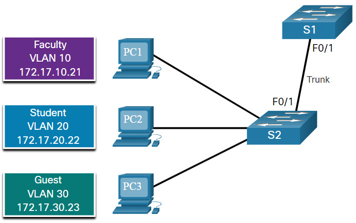
The example shows the configuration of port F0/1 on switch S1 as a trunk port. The native VLAN is changed to VLAN 99 and the allowed VLAN list is restricted to 10, 20, 30, and 99.
S1(config)# interface fastEthernet 0/1
S1(config-if)# switchport mode trunk
S1(config-if)# switchport trunk native vlan 99
S1(config-if)# switchport trunk allowed vlan 10,20,30,99
S1(config-if)# end
Note: This configuration assumes the use of Cisco Catalyst 2960 switches which automatically use 802.1Q encapsulation on trunk links. Other switches may require manual configuration of the encapsulation. Always configure both ends of a trunk link with the same native VLAN. If 802.1Q trunk configuration is not the same on both ends, Cisco IOS Software reports errors.
3.4.3 Verify Trunk Configuration
The switch output displays the configuration of switch port F0/1 on switch S1. The configuration is verified with the show interfaces interface-ID switchport command.
S1# show interfaces fa0/1 switchport
Name: Fa0/1
Switchport: Enabled
Administrative Mode: trunk
Operational Mode: trunk
Administrative Trunking Encapsulation: dot1q
Operational Trunking Encapsulation: dot1q
Negotiation of Trunking: On
Access Mode VLAN: 1 (default)
Trunking Native Mode VLAN: 99 (VLAN0099)
Administrative Native VLAN tagging: enabled
Voice VLAN: none
Administrative private-vlan host-association: none
Administrative private-vlan mapping: none
Administrative private-vlan trunk native VLAN: none
Administrative private-vlan trunk Native VLAN tagging: enabled
Administrative private-vlan trunk encapsulation: dot1q
Administrative private-vlan trunk normal VLANs: none
Administrative private-vlan trunk associations: none
Administrative private-vlan trunk mappings: none
Operational private-vlan: none
Trunking VLANs Enabled: ALL
Pruning VLANs Enabled: 2-1001
(output omitted)
The top highlighted area shows that port F0/1 has its administrative mode set to trunk. The port is in trunking mode. The next highlighted area verifies that the native VLAN is VLAN 99. Further down in the output, the bottom highlighted area shows that VLANs 10, 20, 30, and 99 are enabled on the trunk.
3.4.4 Reset the Trunk to the Default State
Use the no switchport trunk allowed vlan and the no switchport trunk native vlan commands to remove the allowed VLANs and reset the native VLAN of the trunk. When it is reset to the default state, the trunk allows all VLANs and uses VLAN 1 as the native VLAN. The example shows the commands used to reset all trunking characteristics of a trunking interface to the default settings.
S1(config)# interface fa0/1
S1(config-if)# no switchport trunk allowed vlan
S1(config-if)# no switchport trunk native vlan
S1(config-if)# end
The show interfaces f0/1 switchport command reveals that the trunk has been reconfigured to a default state.
S1# show interfaces fa0/1 switchport
Name: Fa0/1
Switchport: Enabled
Administrative Mode: trunk
Operational Mode: trunk
Administrative Trunking Encapsulation: dot1q
Operational Trunking Encapsulation: dot1q
Negotiation of Trunking: On
Access Mode VLAN: 1 (default)
Trunking Native Mode VLAN: 1 (default)
Administrative Native VLAN tagging: enabled
Voice VLAN: none
Administrative private-vlan host-association: none
Administrative private-vlan mapping: none
Administrative private-vlan trunk native VLAN: none
Administrative private-vlan trunk Native VLAN tagging: enabled
Administrative private-vlan trunk encapsulation: dot1q
Administrative private-vlan trunk normal VLANs: none
Administrative private-vlan trunk associations: none
Administrative private-vlan trunk mappings: none
Operational private-vlan: none
Trunking VLANs Enabled: ALL
Pruning VLANs Enabled: 2-1001
(output omitted)
This sample output shows the commands used to remove the trunk feature from the F0/1 switch port on switch S1. The show interfaces f0/1 switchport command reveals that the F0/1 interface is now in static access mode.
S1(config)# interface fa0/1
S1(config-if)# switchport mode access
S1(config-if)# end
S1# show interfaces fa0/1 switchport
Name: Fa0/1
Switchport: Enabled
Administrative Mode: static access
Operational Mode: static access
Administrative Trunking Encapsulation: dot1q
Operational Trunking Encapsulation: native
Negotiation of Trunking: Off
Access Mode VLAN: 1 (default)
Trunking Native Mode VLAN: 1 (default)
Administrative Native VLAN tagging: enabled
(output omitted)
3.4.5 Packet Tracer – Configure Trunks
In this Packet Tracer activity, you will perform the following:
- Verify VLANs
- Configure Trunks
3.4.5 Packet Tracer – Configure Trunks
3.4.6 Lab – Configure VLANs and Trunking
Skills Practice Opportunity
You have the opportunity to practice the following skills:
Part 1: Build the Network and Configure Basic Device Settings
Part 2: Create VLANs and Assign Switch Ports
Part 3: Maintain VLAN Port Assignments and the VLAN Database
Part 4: Configure an 802.1Q Trunk Between the Switches
You can practice these skills using the Packet Tracer or lab equipment, if available.
Packet Tracer – Physical Mode (PTPM)
3.4.6 Packet Tracer – Configure VLANs and Trunking – Physical Mode
Lab Equipment
3.4.6 Lab – Configure VLANs and Trunking
3.5 Dynamic Trunking Protocol
3.5.1 Introduction to DTP
Some Cisco switches have a proprietary protocol that lets them automatically negotiate trunking with a neighboring device. This protocol is called Dynamic Trunking Protocol (DTP). DTP can speed up the configuration process for a network administrator. Ethernet trunk interfaces support different trunking modes. An interface can be set to trunking or nontrunking, or to negotiate trunking with the neighbor interface. Trunk negotiation is managed by DTP, which operates on a point-to-point basis only, between network devices.
DTP is a Cisco proprietary protocol that is automatically enabled on Catalyst 2960 and Catalyst 3650 Series switches. DTP manages trunk negotiation only if the port on the neighbor switch is configured in a trunk mode that supports DTP. Switches from other vendors do not support DTP.
Caution: Some internetworking devices might forward DTP frames improperly, which can cause misconfigurations. To avoid this, turn off DTP on Cisco switch interfaces that are connected to devices that do not support DTP.
The default DTP configuration for Cisco Catalyst 2960 and 3650 switches is dynamic auto.
To enable trunking from a Cisco switch to a device that does not support DTP, use the switchport mode trunk and switchport nonegotiate interface configuration mode commands. This causes the interface to become a trunk, but it will not generate DTP frames.
S1(config-if)# switchport mode trunk
S1(config-if)# switchport nonegotiate
To re-enable dynamic trunking protocol use the switchport mode dynamic auto command.
S1(config-if)# switchport mode dynamic auto
If the ports connecting two switches are configured to ignore all DTP advertisements with the switchport mode trunk and the switchport nonegotiate commands, the ports will stay in trunk port mode. If the connecting ports are set to dynamic auto, they will not negotiate a trunk and will stay in the access mode state, creating an inactive trunk link.
When configuring a port to be in trunk mode, use the switchport mode trunk command. Then there is no ambiguity about which state the trunk is in; it is always on.
3.5.2 Negotiated Interface Modes
The switchport mode command has additional options for negotiating the interface mode. The full command syntax is the following:
Switch(config)# switchport mode { access | dynamic { auto | desirable } | trunk }
The options are described in the table.
| Option | Description |
|---|---|
| access | Puts the interface (access port) into permanent nontrunking mode and negotiates to convert the link into a nontrunk link. The interface becomes a nontrunk interface, regardless of whether the neighboring interface is a trunk interface. |
| dynamic auto | Makes the interface able to convert the link to a trunk link. The interface becomes a trunk interface if the neighboring interface is set to trunk or desirable mode. The default switchport mode for all Ethernet interfaces is dynamic auto. |
| dynamic desirable | Makes the interface actively attempt to convert the link to a trunk link. The interface becomes a trunk interface if the neighboring interface is set to trunk, desirable, or dynamic auto mode. |
| trunk | Puts the interface into permanent trunking mode and negotiates to convert the neighboring link into a trunk link. The interface becomes a trunk interface even if the neighboring interface is not a trunk interface. |
Use the switchport nonegotiate interface configuration command to stop DTP negotiation. The switch does not engage in DTP negotiation on this interface. You can use this command only when the interface switchport mode is access or trunk. You must manually configure the neighboring interface as a trunk interface to establish a trunk link.
3.5.3 Results of a DTP Configuration
The table illustrates the results of the DTP configuration options on opposite ends of a trunk link connected to Catalyst 2960 switch ports. Best practice is to configure trunk links statically whenever possible.
| Dynamic Auto | Dynamic Desirable | Trunk | Access | |
|---|---|---|---|---|
| Dynamic Auto | Access | Trunk | Trunk | Access |
| Dynamic Desirable | Trunk | Trunk | Trunk | Access |
| Trunk | Trunk | Trunk | Trunk | Limited connectivity |
| Access | Access | Access | Limited connectivity | Access |
3.5.4 Verify DTP Mode
The default DTP mode is dependent on the Cisco IOS Software version and on the platform. To determine the current DTP mode, issue the show dtp interface command as shown in the output.
S1# show dtp interface fa0/1
DTP information for FastEthernet0/1:
TOS/TAS/TNS: ACCESS/AUTO/ACCESS
TOT/TAT/TNT: NATIVE/NEGOTIATE/NATIVE
Neighbor address 1: C80084AEF101
Neighbor address 2: 000000000000
Hello timer expiration (sec/state): 11/RUNNING
Access timer expiration (sec/state): never/STOPPED
Negotiation timer expiration (sec/state): never/STOPPED
Multidrop timer expiration (sec/state): never/STOPPED
FSM state: S2:ACCESS
# times multi & trunk 0
Enabled: yes
In STP: no
Note: A general best practice is to set the interface to trunk and nonegotiate when a trunk link is required. On links where trunking is not intended, DTP should be turned off.
3.5.5 Packet Tracer – Configure DTP
In this Packet Tracer activity, you will configure and verify DTP.
3.5.5 Packet Tracer – Configure DTP
3.6 Module Practice and Quiz
3.6.1 Packet Tracer – Implement VLANs and Trunking
In this Packet Tracer activity, you will perform the following:
- Configure VLANs
- Assign Ports to VLANs
- Configure Static Trunking
- Configure Dynamic Trunking
3.6.1 Packet Tracer – Implement VLANs and Trunking
3.6.2 Lab – Implement VLANs and Trunking
In this lab, you will perform the following:
- Build the Network and Configure Basic Device Settings
- Create VLANs and Assign Switch Ports
- Configure an 802.1Q Trunk between the Switches
3.6.2 Lab – Implement VLANs and Trunking
3.6.3 What did I learn in this module?
Overview of VLANs
Virtual LANs (VLANs) are a group of devices that can communicate as if each device was attached to the same cable. VLANs are based on logical instead of physical connections. Administrators use VLANs to segment networks based on factors such as function, team, or application. Each VLAN is considered a separate logical network. Any switch port can belong to a VLAN. A VLAN creates a logical broadcast domain that can span multiple physical LAN segments. VLANs improve network performance by separating large broadcast domains into smaller ones. Each VLAN in a switched network corresponds to an IP network; therefore, VLAN design must use a hierarchical network-addressing scheme. Types of VLANs include the default VLAN, data VLANs, the native VLAN, management VLANs. and voice VLANs.
VLANs in a Multi-Switched Environment
A VLAN trunk does not belong to a specific VLAN. It is a conduit for multiple VLANs between switches and routers. A VLAN trunk is a point-to-point link between two network devices that carries more than one VLAN. A VLAN trunk extends VLANs across an entire network. When VLANs are implemented on a switch, the transmission of unicast, multicast, and broadcast traffic from a host in a particular VLAN are restricted to the devices that are in that VLAN. VLAN tag fields include the type, user priority, CFI and VID. Some devices add a VLAN tag to native VLAN traffic. If an 802.1Q trunk port receives a tagged frame with the VID that is the same as the native VLAN, it drops the frame. A separate voice VLAN is required to support VoIP. QoS and security policies can be applied to voice traffic. Voice VLAN traffic must be tagged with an appropriate Layer 2 CoS priority value.
VLAN Configuration
Different Cisco Catalyst switches support various numbers of VLANs including normal range VLANs and extended range VLANs. When configuring normal range VLANs, the configuration details are stored in flash memory on the switch in a file called vlan.dat. Although it is not required, it is good practice to save running configuration changes to the startup configuration. After creating a VLAN, the next step is to assign ports to the VLAN. There are several commands for defining a port to be an access port and assigning it to a VLAN. VLANs are configured on the switch port and not on the end device. An access port can belong to only one data VLAN at a time. However, a port can also be associated to a voice VLAN. For example, a port connected to an IP phone and an end device would be associated with two VLANs: one for voice and one for data. After a VLAN is configured, VLAN configurations can be validated using Cisco IOS show commands. If the switch access port has been incorrectly assigned to a VLAN, then simply re-enter the switchport access vlan vlan-id interface configuration command with the correct VLAN ID. The no vlan vlan-id global configuration mode command is used to remove a VLAN from the switch vlan.dat file.
VLAN Trunks
A VLAN trunk is an OSI Layer 2 link between two switches that carries traffic for all VLANs. There are several commands to configure the interconnecting ports. To verify VLAN trunk configuration use the show interfaces interface-ID switchport command. Use the no switchport trunk allowed vlan and the no switchport trunk native vlan commands to remove the allowed VLANs and reset the native VLAN of the trunk.
Dynamic Trunking Protocol
An interface can be set to trunking or nontrunking, or to negotiate trunking with the neighbor interface. Trunk negotiation is managed by the Dynamic Trunking Protocol (DTP), which operates on a point-to-point basis only, between network devices. DTP is a Cisco proprietary protocol that manages trunk negotiation only if the port on the neighbor switch is configured in a trunk mode that supports DTP. To enable trunking from a Cisco switch to a device that does not support DTP, use the switchport mode trunk and switchport nonegotiate interface configuration mode commands. The switchport mode command has additional options for negotiating the interface mode including access, dynamic auto, dynamic desirable, and trunk. To verify the current DTP mode, issue the show dtp interface command.

