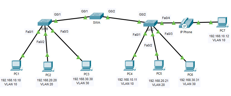
3.6.1 Packet Tracer – Implement VLANs and Trunking (Instructor Version)

Addressing Table
| Device | Interface | IP Address | Subnet Mask | Switchport | VLAN |
|---|---|---|---|---|---|
| PC1 | NIC | 192.168.10.10 | 255.255.255.0 | SWB F0/1 | VLAN 10 |
| PC2 | NIC | 192.168.20.20 | 255.255.255.0 | SWB F0/2 | VLAN 20 |
| PC3 | NIC | 192.168.30.30 | 255.255.255.0 | SWB F0/3 | VLAN 30 |
| PC4 | NIC | 192.168.10.11 | 255.255.255.0 | SWC F0/1 | VLAN 10 |
| PC5 | NIC | 192.168.20.21 | 255.255.255.0 | SWC F0/2 | VLAN 20 |
| PC6 | NIC | 192.168.30.31 | 255.255.255.0 | SWC F0/3 | VLAN 30 |
| PC7 | NIC | 192.168.10.12 | 255.255.255.0 | SWC F0/4 | VLAN 10 VLAN 40 (Voice) |
| SWA | SVI | 192.168.99.252 | 255.255.255.0 | N/A | VLAN 99 |
| SWB | SVI | 192.168.99.253 | 255.255.255.0 | N/A | VLAN 99 |
| SWC | SVI | 192.168.99.254 | 255.255.255.0 | N/A | VLAN 99 |
Objectives
- Part 1: Configure VLANs
- Part 2: Assign Ports to VLANs
- Part 3: Configure Static Trunking
- Part 4: Configure Dynamic Trunking
Background
You are working in a company that is getting ready to deploy a set of new 2960 switches in a branch office.
You are working in the lab to test out the VLAN and trunking configurations that are planned. Configure and test the VLANs and trunks.
Instructions
Part 1: Configure VLANs
Configure VLANs on all three switches. Refer to the VLAN Table. Note that the VLAN names must match the values in the table exactly.
VLAN Table
| VLAN Number | VLAN Name |
|---|---|
| 10 | Admin |
| VLAN Number | VLAN Name |
| 20 | Accounts |
| 30 | HR |
| 40 | Voice |
| 99 | Management |
| 100 | Native |
Switch A / Switch B / Switch C
enable
configure terminal
vlan 10
name Admin
vlan 20
name Accounts
vlan 30
name HR
vlan 40
name Voice
vlan 99
name Management
vlan 100
name Native
Part 2: Assign Ports to VLANs
Step 1: Assign access ports to VLANs
On SWB and SWC, assign ports to the VLANs. Refer to the Addressing Table.
Switch B
interface f0/1
switchport mode access
switchport access vlan 10
interface f0/2
switchport mode access
switchport access vlan 20
interface f0/3
switchport mode access
switchport access vlan 30
Switch C
interface f0/1
switchport mode access
switchport access vlan 10
interface f0/2
switchport mode access
switchport access vlan 20
interface f0/3
switchport mode access
switchport access vlan 30
interface f0/4
switchport mode access
switchport access vlan 10
Step 2: Configure the Voice VLAN port
Configure the appropriate port on switch SWC for voice VLAN functionality.
Switch C
interface f0/4
mls qos trust cos
switchport voice vlan 40
Step 3: Configure the virtual management interfaces
a. Create the virtual management interfaces, on all three switches.
b. Address the virtual management interfaces according to the Addressing Table.
c. The switches should not be able to ping each other.
Part 3: Configure Static Trunking
a. Configure the link between SWA and SWB as a static trunk. Disable dynamic trunking on this port.
b. Disable DTP on the switch port on both ends of the trunk link.
c. Configure the trunk with the native VLAN and eliminate native VLAN conflicts if any.
SWA(config)#interface g0/1
SWA(config-if)#switchport mode trunk
SWA(config-if)#switchport nonegotiate
SWA(config-if)#switchport trunk native vlan 100
SWB(config)#interface g0/1
SWB(config-if)#switchport mode trunk
SWB(config-if)#switchport nonegotiate
SWB(config-if)#switchport trunk native vlan 100
Part 4: Configure Dynamic Trunking
a. Assume that the trunk port on SWC is set to the default DTP mode for 2960 switches. Configure G0/2 on SWA so that it successfully negotiates trunking with SWC.
b. Configure the trunk with the native VLAN and eliminate native VLAN conflicts if any.
SWA(config)#interface g0/2
SWA(config-if)#switchport mode dynamic desirable
SWC(config)#interface g0/2
SWC(config-if)#switchport mode trunk
SWC(config-if)#switchport trunk native vlan 100
Answer Scripts
Switch SWA
enaable
conf t
vlan 10
 name Admin
vlan 20
 name Accounts
vlan 30
 name HR
vlan 40
 name Voice
vlan 99
 name Management
vlan 100
 name Native
interface GigabitEthernet0/1
 switchport trunk native vlan 100
 switchport mode trunk
 switchport nonegotiate
interface GigabitEthernet0/2
 switchport trunk native vlan 100
 switchport mode dynamic desirable
interface Vlan1
 no ip address
 shutdown
interface Vlan99
ip address 192.168.99.252 255.255.255.0
end
Switch SWB
enaable
conf t
vlan 10
 name Admin
vlan 20
 name Accounts
vlan 30
 name HR
vlan 40
 name Voice
vlan 99
 name Management
vlan 100
 name Native
interface FastEthernet0/1
 switchport access vlan 10
 switchport mode access
interface FastEthernet0/2
 switchport access vlan 20
 switchport mode access
interface FastEthernet0/3
 switchport access vlan 30
 switchport mode access
interface GigabitEthernet0/1
 switchport trunk native vlan 100
 switchport mode trunk
 switchport nonegotiate
interface Vlan99
ip address 192.168.99.253 255.255.255.0
end
Switch SWC
enable
conf t
vlan 10
 name Admin
vlan 20
 name Accounts
vlan 30
 name HR
vlan 40
 name Voice
vlan 99
 name Management
vlan 100
 name Native
interface FastEthernet0/1
 switchport access vlan 10
 switchport mode access
interface FastEthernet0/2
 switchport access vlan 20
 switchport mode access
interface FastEthernet0/3
 switchport access vlan 30
 switchport mode access
interface FastEthernet0/4
 switchport access vlan 10
 switchport mode access
 switchport voice vlan 40
 mls qos trust cos
interface GigabitEthernet0/2
 switchport trunk native vlan 100
 switchport mode trunk
interface Vlan99
ip address 192.168.99.254 255.255.255.0
end

You miss spelled enable as enaable.
ø
no enaable