4.0. Introduction
4.0.1 Why should I take this module?
Welcome to Inter-VLAN Routing!
Now you know how to segment and organize your network into VLANs. Hosts can communicate with other hosts in the same VLAN, and you no longer have hosts sending out broadcast messages to every other device in your network, eating up needed bandwidth. But what if a host in one VLAN needs to communicate with a host in a different VLAN? If you are a network administrator, you know that people will want to communicate with other people outside of your network. This is where inter-VLAN routing can help you. Inter-VLAN routing uses a Layer 3 device such as a router or a Layer 3 switch. Let’s take your VLAN expertise and combine it with your network layer skills and put them to the test!
4.0.2 What will I learn to do in this module?
Module Title: Inter-VLAN Routing
Module Objective: Troubleshoot inter-VLAN routing on Layer 3 devices.
| Topic Title | Topic Objective |
|---|---|
| Inter-VLAN Routing Operation | Describe options for configuring inter-VLAN routing. |
| Router-on-a-Stick Inter-VLAN Routing | Configure router-on-a-stick inter-VLAN routing. |
| Inter-VLAN Routing using Layer 3 Switches | Configure inter-VLAN routing using Layer 3 switching. |
| Troubleshoot Inter-VLAN Routing | Troubleshoot common inter-VLAN configuration issues. |
4.1 Inter-VLAN Routing Operation
4.1.1 What is Inter-VLAN Routing?
VLANs are used to segment switched Layer 2 networks for a variety of reasons. Regardless of the reason, hosts in one VLAN cannot communicate with hosts in another VLAN unless there is a router or a Layer 3 switch to provide routing services.
Inter-VLAN routing is the process of forwarding network traffic from one VLAN to another VLAN.
There are three inter-VLAN routing options:
- Legacy Inter-VLAN routing – This is a legacy solution. It does not scale well.
- Router-on-a-Stick – This is an acceptable solution for a small to medium-sized network.
- Layer 3 switch using switched virtual interfaces (SVIs) – This is the most scalable solution for medium to large organizations.
4.1.2 Legacy Inter-VLAN Routing
The first inter-VLAN routing solution relied on using a router with multiple Ethernet interfaces. Each router interface was connected to a switch port in different VLANs. The router interfaces served as the default gateways to the local hosts on the VLAN subnet.
For example, refer to the topology where R1 has two interfaces connected to switch S1.
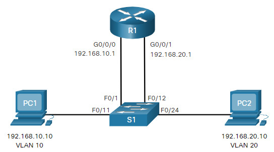
Notice in the example MAC address table of S1 is populated as follows:
- Fa0/1 port is assigned to VLAN 10 and is connected to the R1 G0/0/0 interface.
- Fa0/11 port is assigned to VLAN 10 and is connected to PC1.
- Fa0/12 port is assigned to VLAN 20 and is connected to the R1 G0/0/1 interface.
- Fa0/11 port is assigned to VLAN 20 and is connected to PC2.
MAC Address table for S1
| Port | MAC Address | VLAN |
|---|---|---|
| F0/1 | R1 G0/0/0 MAC | 10 |
| F0/11 | PC1 MAC | 10 |
| F0/12 | R1 G0/0/1 MAC | 20 |
| F0/24 | PC2 MAC | 20 |
When PC1 sends a packet to PC2 on another network, it forwards it to its default gateway 192.168.10.1. R1 receives the packet on its G0/0/0 interface and examines the destination address of the packet. R1 then routes the packet out its G0/0/1 interface to the F0/12 port in VLAN 20 on S1. Finally, S1 forwards the frame to PC2.
Legacy inter-VLAN routing using physical interfaces works, but it has a significant limitation. It is not reasonably scalable because routers have a limited number of physical interfaces. Requiring one physical router interface per VLAN quickly exhausts the physical interface capacity of a router.
In our example, R1 required two separate Ethernet interfaces to route between VLAN 10 and VLAN 20. What if there were six (or more) VLANs to interconnect? A separate interface would be required for each VLAN. Obviously, this solution is not scalable.
Note: This method of inter-VLAN routing is no longer implemented in switched networks and is included for explanation purposes only.
4.1.3 Router-on-a-Stick Inter-VLAN Routing
The ‘router-on-a-stick’ inter-VLAN routing method overcomes the limitation of the legacy inter-VLAN routing method. It only requires one physical Ethernet interface to route traffic between multiple VLANs on a network.
A Cisco IOS router Ethernet interface is configured as an 802.1Q trunk and connected to a trunk port on a Layer 2 switch. Specifically, the router interface is configured using subinterfaces to identify routable VLANs.
The configured subinterfaces are software-based virtual interfaces. Each is associated with a single physical Ethernet interface. Subinterfaces are configured in software on a router. Each subinterface is independently configured with an IP address and VLAN assignment. Subinterfaces are configured for different subnets that correspond to their VLAN assignment. This facilitates logical routing.
When VLAN-tagged traffic enters the router interface, it is forwarded to the VLAN subinterface. After a routing decision is made based on the destination IP network address, the router determines the exit interface for the traffic. If the exit interface is configured as an 802.1q subinterface, the data frames are VLAN-tagged with the new VLAN and sent back out the physical interface.
The figure to view an animation of how a router-on-a-stick performs its routing function.
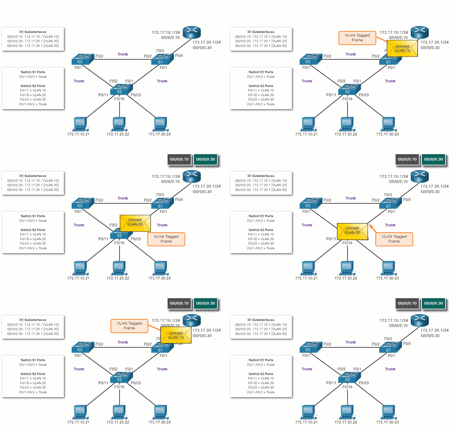
As seen in the animation, PC1 on VLAN 10 is communicating with PC3 on VLAN 30. When R1 accepts the tagged unicast traffic on VLAN 10, it routes that traffic to VLAN 30, using its configured subinterfaces. Switch S2 removes the VLAN tag of the unicast frame and forwards the frame out to PC3 on port F0/23.
Note: The router-on-a-stick method of inter-VLAN routing does not scale beyond 50 VLANs.
4.1.4 Inter-VLAN Routing on a Layer 3 Switch
The modern method of performing inter-VLAN routing is to use Layer 3 switches and switched virtual interfaces (SVI). An SVI is a virtual interface that is configured on a Layer 3 switch, as shown in the figure.
Note: A Layer 3 switch is also called a multilayer switch as it operates at Layer 2 and Layer 3. However, in this course we use the term Layer 3 switch.
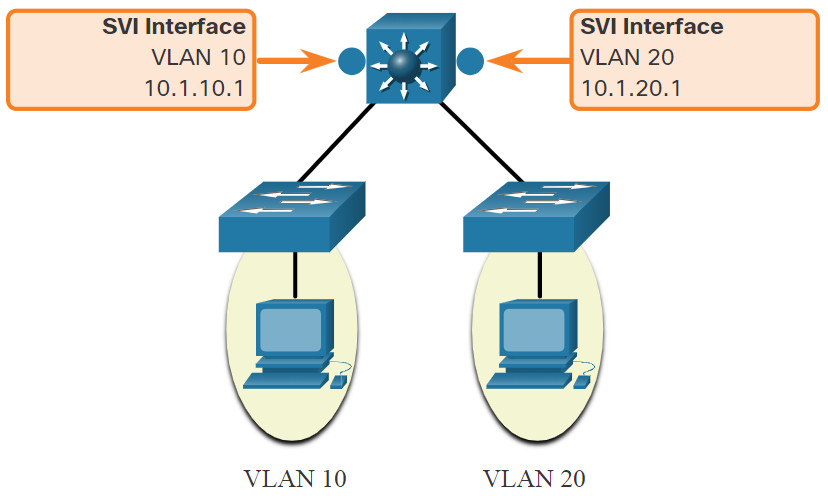
Inter-VLAN SVIs are created the same way that the management VLAN interface is configured. The SVI is created for a VLAN that exists on the switch. Although virtual, the SVI performs the same functions for the VLAN as a router interface would. Specifically, it provides Layer 3 processing for packets that are sent to or from all switch ports associated with that VLAN.
The following are advantages of using Layer 3 switches for inter-VLAN routing:
- They are much faster than router-on-a-stick because everything is hardware switched and routed.
- There is no need for external links from the switch to the router for routing.
- They are not limited to one link because Layer 2 EtherChannels can be used as trunk links between the switches to increase bandwidth.
- Latency is much lower because data does not need to leave the switch in order to be routed to a different network.
- They more commonly deployed in a campus LAN than routers.
The only disadvantage is that Layer 3 switches are more expensive.
4.2 Router-on-a-Stick Inter-VLAN Routing
4.2.1 Router-on-a-Stick Scenario
In the previous topic, three different ways to create inter-VLAN routing were listed, and legacy inter-VLAN routing was detailed. This topic details how to configure router-on-a-stick inter-VLAN routing. You can see in the figure that the router is not in the center of the topology but instead, appears to be on a stick near the border, hence the name.
In the figure, the R1 GigabitEthernet 0/0/1 interface is connected to the S1 FastEthernet 0/5 port. The S1 FastEthernet 0/1 port is connected to the S2 FastEthernet 0/1 port. These are trunk links that are required to forward traffic within and between VLANs.
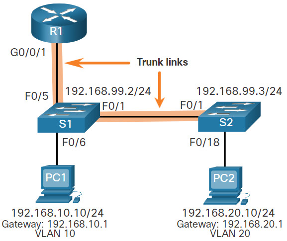
To route between VLANs, the R1 GigabitEthernet 0/0/1 interface is logically divided into three subinterfaces, as shown in the table. The table also shows the three VLANs that will be configured on the switches.
| Subinterface | VLAN | IP Address |
|---|---|---|
| G0/0/1.10 | 10 | 192.168.10.1/24 |
| G0/0/1.20 | 20 | 192.168.20.1/24 |
| G0/0/1.30 | 99 | 192.168.99.1/24 |
4.2.2 S1 VLAN and Trunking Configuration
Complete the following steps to configure S1 with VLANs and trunking:
Step 1. Create and name the VLANs.
Step 2. Create the management interface.
Step 3. Configure access ports.
Step 4. Configure trunking ports.
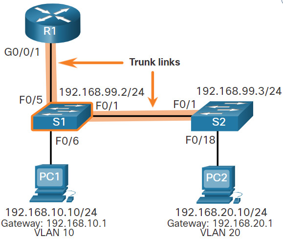
The configuration step.
1. Create and name the VLANs.
First, the VLANs are created and named. VLANs are only created after you exit out of VLAN subconfiguration mode.
S1(config)# vlan 10
S1(config-vlan)# name LAN10
S1(config-vlan)# exit
S1(config)# vlan 20
S1(config-vlan)# name LAN20
S1(config-vlan)# exit
S1(config)# vlan 99
S1(config-vlan)# name Management
S1(config-vlan)# exit
S1(config)#
2. Create the management interface.
Next, the management interface is created on VLAN 99 along with the default gateway of R1.
S1(config)# interface vlan 99
S1(config-if)# ip add 192.168.99.2 255.255.255.0
S1(config-if)# no shut
S1(config-if)# exit
S1(config)# ip default-gateway 192.168.99.1
S1(config)#
3. Configure access ports.
Next, port Fa0/6 connecting to PC1 is configured as an access port in VLAN 10. Assume PC1 has been configured with the correct IP address and default gateway.
S1(config)# interface fa0/6
S1(config-if)# switchport mode access
S1(config-if)# switchport access vlan 10
S1(config-if)# no shut
S1(config-if)# exit
S1(config)#
4. Configure trunking ports.
Finally, ports Fa0/1 connecting to S2 and Fa05 connecting to R1 are configured as trunk ports.
S1(config)# interface fa0/1
S1(config-if)# switchport mode trunk
S1(config-if)# no shut
S1(config-if)# exit
S1(config)# interface fa0/5
S1(config-if)# switchport mode trunk
S1(config-if)# no shut
S1(config-if)# end
*Mar  1 00:23:43.093: %LINEPROTO-5-UPDOWN: Line protocol on Interface FastEthernet0/1, changed state to up
*Mar  1 00:23:44.511: %LINEPROTO-5-UPDOWN: Line protocol on Interface FastEthernet0/5, changed state to up
4.2.3 S2 VLAN and Trunking Configuration
The configuration for S2 is similar to S1.
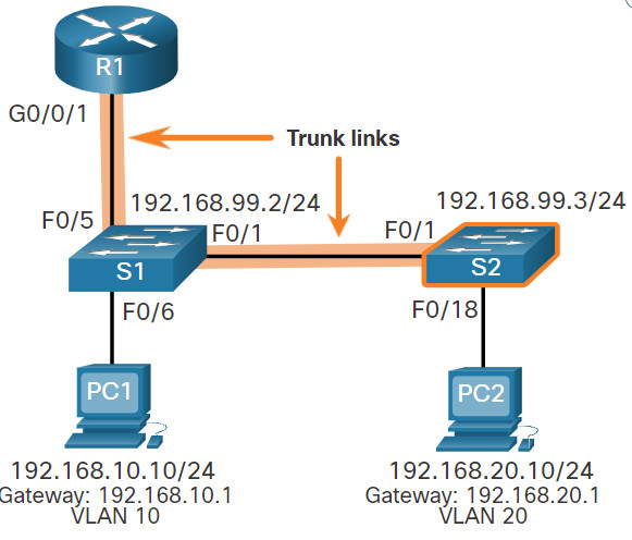
S2(config)# vlan 10
S2(config-vlan)# name LAN10
S2(config-vlan)# exit
S2(config)# vlan 20
S2(config-vlan)# name LAN20
S2(config-vlan)# exit
S2(config)# vlan 99
S2(config-vlan)# name Management
S2(config-vlan)# exit
S2(config)#
S2(config)# interface vlan 99
S2(config-if)# ip add 192.168.99.3 255.255.255.0
S2(config-if)# no shut
S2(config-if)# exit
S2(config)# ip default-gateway 192.168.99.1
S2(config)# interface fa0/18
S2(config-if)# switchport mode access
S2(config-if)# switchport access vlan 20
S2(config-if)# no shut
S2(config-if)# exit
S2(config)# interface fa0/1
S2(config-if)# switchport mode trunk
S2(config-if)# no shut
S2(config-if)# exit
S2(config-if)# end
*Mar  1 00:23:52.137: %LINEPROTO-5-UPDOWN: Line protocol on Interface FastEthernet0/1, changed state to up
4.2.4 R1 Subinterface Configuration
The router-on-a-stick method requires you to create a subinterface for each VLAN to be routed.
A subinterface is created using the interface interface_id subinterface_id global configuration mode command. The subinterface syntax is the physical interface followed by a period and a subinterface number. Although not required, it is customary to match the subinterface number with the VLAN number.
Each subinterface is then configured with the following two commands:
- encapsulation dot1q vlan_id [native] – This command configures the subinterface to respond to 802.1Q encapsulated traffic from the specified vlan-id. The native keyword option is only appended to set the native VLAN to something other than VLAN 1.
- ip address ip-address subnet-mask – This command configures the IPv4 address of the subinterface. This address typically serves as the default gateway for the identified VLAN.
Repeat the process for each VLAN to be routed. Each router subinterface must be assigned an IP address on a unique subnet for routing to occur.
When all subinterfaces have been created, enable the physical interface using the no shutdown interface configuration command. If the physical interface is disabled, all subinterfaces are disabled.
In the following configuration, the R1 G0/0/1 subinterfaces are configured for VLANs 10, 20, and 99.
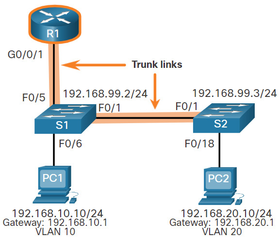
R1(config)# interface G0/0/1.10
R1(config-subif)# description Default Gateway for VLAN 10
R1(config-subif)# encapsulation dot1Q 10
R1(config-subif)# ip add 192.168.10.1 255.255.255.0
R1(config-subif)# exit
R1(config)#
R1(config)# interface G0/0/1.20
R1(config-subif)# description Default Gateway for VLAN 20
R1(config-subif)# encapsulation dot1Q 20
R1(config-subif)# ip add 192.168.20.1 255.255.255.0
R1(config-subif)# exit
R1(config)#
R1(config)# interface G0/0/1.99
R1(config-subif)# description Default Gateway for VLAN 99
R1(config-subif)# encapsulation dot1Q 99
R1(config-subif)# ip add 192.168.99.1 255.255.255.0
R1(config-subif)# exit
R1(config)#
R1(config)# interface G0/0/1
R1(config-if)# description Trunk link to S1
R1(config-if)# no shut
R1(config-if)# end
R1#
*Sep 15 19:08:47.015: %LINK-3-UPDOWN: Interface GigabitEthernet0/0/1, changed state to down
*Sep 15 19:08:50.071: %LINK-3-UPDOWN: Interface GigabitEthernet0/0/1, changed state to up
*Sep 15 19:08:51.071: %LINEPROTO-5-UPDOWN: Line protocol on Interface GigabitEthernet0/0/1, changed state to up
R1#
4.2.5 Verify Connectivity Between PC1 and PC2
The router-on-a-stick configuration is complete after the switch trunk and the router subinterfaces have been configured. The configuration can be verified from the hosts, router, and switch.
From a host, verify connectivity to a host in another VLAN using the ping command. It is a good idea to first verify the current host IP configuration using the ipconfig Windows host command.
C:\Users\PC1> ipconfig
Windows IP Configuration
Ethernet adapter Ethernet0:
  Connection-specific DNS Suffix . :
  Link-local IPv6 Address          : fe80::5c43:ee7c:2959:da68%6
  IPv4 Address                     : 192.168.10.10
  Subnet Mask                      : 255.255.255.0
  Default Gateway                  : 192.168.10.1
C:\Users\PC1>
The output confirms the IPv4 address and default gateway of PC1. Next, use ping to verify connectivity with PC2 and S1, as shown in the figure. The ping output successfully confirms inter-VLAN routing is operating.
C:\Users\PC1> ping 192.168.20.10
Pinging 192.168.20.10 with 32 bytes of data:
Reply from 192.168.20.10: bytes=32 time<1ms TTL=127
Reply from 192.168.20.10: bytes=32 time<1ms TTL=127
Reply from 192.168.20.10: bytes=32 time<1ms TTL=127
Reply from 192.168.20.10: bytes=32 time<1ms TTL=127 Ping statistics for 192.168.20.10: Packets: Sent = 4, Received = 4, Lost = 0 (0% loss). Approximate round trip times in milli-seconds: Minimum = 0ms, Maximum = 0ms, Average = 0ms C:\Users\PC1>
C:\Users\PC1> ping 192.168.99.2
Pinging 192.168.99.2 with 32 bytes of data:
Request timed out.
Request timed out.
Reply from 192.168.99.2: bytes=32 time=2ms TTL=254
Reply from 192.168.99.2: bytes=32 time=1ms TTL=254	|
Ping statistics for 192.168.99.2:
    Packets: Sent = 4, Received = 2, Lost = 2 (50% loss).
Approximate round trip times in milli-seconds:
    Minimum = 1ms, Maximum = 2ms, Average = 1ms
C:\Users\PC1>
4.2.6 Router-on-a-Stick Inter-VLAN Routing Verification
In addition to using ping between devices, the following show commands can be used to verify and troubleshoot the router-on-a-stick configuration.
-
- show ip route
Verify that the subinterfaces are appearing in the routing table of R1 by using theshow ip routecommand. Notice that there are three connected routes (C) and their respective exit interfaces for each routable VLAN. The output confirms that the correct subnets, VLANs, and subinterfaces are active.R1# show ip route | begin Gateway Gateway of last resort is not set 192.168.10.0/24 is variably subnetted, 2 subnets, 2 masks C 192.168.10.0/24 is directly connected, GigabitEthernet0/0/1.10 L 192.168.10.1/32 is directly connected, GigabitEthernet0/0/1.10 192.168.20.0/24 is variably subnetted, 2 subnets, 2 masks C 192.168.20.0/24 is directly connected, GigabitEthernet0/0/1.20 L 192.168.20.1/32 is directly connected, GigabitEthernet0/0/1.20 192.168.99.0/24 is variably subnetted, 2 subnets, 2 masks C 192.168.99.0/24 is directly connected, GigabitEthernet0/0/1.99 L 192.168.99.1/32 is directly connected, GigabitEthernet0/0/1.99 R1# - show ip interface brief
Another useful router command isshow ip interface brief, as shown in the output. The output confirms that the subinterfaces have the correct IPv4 address configured, and that they are operational.R1# show ip interface brief | include up GigabitEthernet0/0/1 unassigned YES unset up up Gi0/0/1.10 192.168.10.1 YES manual up up Gi0/0/1.20 192.168.20.1 YES manual up up Gi0/0/1.99 192.168.99.1 YES manual up up R1#
- show interfaces
Subinterfaces can be verified using theshow interfacessubinterface-id command, as shown.R1# show interfaces g0/0/1.10 GigabitEthernet0/0/1.10 is up, line protocol is up Hardware is ISR4221-2x1GE, address is 10b3.d605.0301 (bia 10b3.d605.0301) Description: Default Gateway for VLAN 10 Internet address is 192.168.10.1/24 MTU 1500 bytes, BW 100000 Kbit/sec, DLY 100 usec, reliability 255/255, txload 1/255, rxload 1/255 Encapsulation 802.1Q Virtual LAN, Vlan ID 10. ARP type: ARPA, ARP Timeout 04:00:00 Keepalive not supported Last clearing of "show interface" counters never R1# - show interfaces trunk
- show ip route
The misconfiguration could also be on the trunking port of the switch. Therefore, it is also useful to verify the active trunk links on a Layer 2 switch by using the show interfaces trunk command, as shown in the output. The output confirms that the link to R1 is trunking for the required VLANs.
Note: Although VLAN 1 was not explicitly configured, it was automatically included because control traffic on trunk links will always be forwarded on VLAN 1.
S1# show interfaces trunk
Port        Mode             Encapsulation  Status        Native vlan
Fa0/1       on               802.1q         trunking      1
Fa0/5       on               802.1q         trunking      1
Port        Vlans allowed on trunk
Fa0/1       1-4094
Fa0/5       1-4094
Port        Vlans allowed and active in management domain
Fa0/1       1,10,20,99
Fa0/5       1,10,20,99
Port        Vlans in spanning tree forwarding state and not pruned
Fa0/1       1,10,20,99
Fa0/5       1,10,20,99
S1#
4.2.7 Packet Tracer – Configure Router-on-a-Stick Inter-VLAN Routing
In this activity, you will check for connectivity prior to implementing inter-VLAN routing. Then you will configure VLANs and inter-VLAN routing. Finally, you will enable trunking and verify connectivity between VLANs.
4.2.7 Packet Tracer – Configure Router-on-a-Stick Inter-VLAN Routing
4.2.8 Lab – Configure Router-on-a-Stick Inter-VLAN Routing
In this lab, you will complete the following objectives:
- Part 1: Build the Network and Configure Basic Device Settings
- Part 2: Configure Switches with VLANs and Trunking
- Part 3: Configure Trunk-Based Inter-VLAN Routing
4.2.8 Lab – Configure Router-on-a-Stick Inter-VLAN Routing
4.3 Inter-VLAN Routing using Layer 3 Switches
4.3.1 Layer 3 Switch Inter-VLAN Routing
Modern, enterprise networks rarely use router-on-a-stick because it does not scale easily to meet requirements. In these very large networks, network administrators use Layer 3 switches to configure inter-VLAN routing.
Inter-VLAN routing using the router-on-a-stick method is simple to implement for a small to medium-sized organization. However, a large enterprise requires a faster, much more scalable method to provide inter-VLAN routing.
Enterprise campus LANs use Layer 3 switches to provide inter-VLAN routing. Layer 3 switches use hardware-based switching to achieve higher-packet processing rates than routers. Layer 3 switches are also commonly implemented in enterprise distribution layer wiring closets.
Capabilities of a Layer 3 switch include the ability to do the following:
- Route from one VLAN to another using multiple switched virtual interfaces (SVIs).
- Convert a Layer 2 switchport to a Layer 3 interface (i.e., a routed port). A routed port is similar to a physical interface on a Cisco IOS router.
To provide inter-VLAN routing, Layer 3 switches use SVIs. SVIs are configured using the same interface vlan vlan-id command used to create the management SVI on a Layer 2 switch. A Layer 3 SVI must be created for each of the routable VLANs.
4.3.2 Layer 3 Switch Scenario
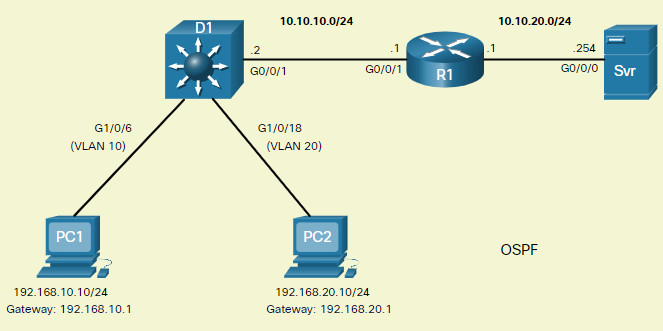
In the figure, the Layer 3 switch, D1, is connected to two hosts on different VLANs. PC1 is in VLAN 10 and PC2 is in VLAN 20, as shown. The Layer 3 switch will provide inter-VLAN routing services to the two hosts.
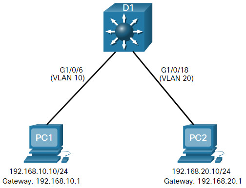
The table shows the IP addresses for each VLAN.
D1 VLAN IP Addresses
| VLAN Interface | IP Address |
|---|---|
| 10 | 192.168.10.1/24 |
| 20 | 192.168.20.1/24 |
4.3.3 Layer 3 Switch Configuration
Complete the following steps to configure S1 with VLANs and trunking:
Step 1. Create the VLANs.
First, create the two VLANs as shown in the output.
D1(config)# vlan 10
D1(config-vlan)# name LAN10
D1(config-vlan)# vlan 20
D1(config-vlan)# name LAN20
D1(config-vlan)# exit
D1(config)#
Step 2. Create the SVI VLAN interfaces.
Configure the SVI for VLANs 10 and 20. The IP addresses that are configured will serve as the default gateways to the hosts in the respective VLANs. Notice the informational messages showing the line protocol on both SVIs changed to up.
D1(config)# interface vlan 10
D1(config-if)# description Default Gateway SVI for 192.168.10.0/24
D1(config-if)# ip add 192.168.10.1 255.255.255.0
D1(config-if)# no shut
D1(config-if)# exit
D1(config)#
D1(config)# int vlan 20
D1(config-if)# description Default Gateway SVI for 192.168.20.0/24
D1(config-if)# ip add 192.168.20.1 255.255.255.0
D1(config-if)# no shut
D1(config-if)# exit
D1(config)#
*Sep 17 13:52:16.053: %LINEPROTO-5-UPDOWN: Line protocol on Interface Vlan10, changed state to up
*Sep 17 13:52:16.160: %LINEPROTO-5-UPDOWN: Line protocol on Interface Vlan20, changed state to up
Step 3. Configure access ports.
Next, configure the access ports connecting to the hosts and assign them to their respective VLANs.
D1(config)# interface GigabitEthernet1/0/6
D1(config-if)# description Access port to PC1
D1(config-if)# switchport mode access
D1(config-if)# switchport access vlan 10
D1(config-if)# exit
D1(config)#
D1(config)# interface GigabitEthernet1/0/18
D1(config-if)# description Access port to PC2
D1(config-if)# switchport mode access
D1(config-if)# switchport access vlan 20
D1(config-if)# exit
Step 4. Enable IP routing.
Finally, enable IPv4 routing with the ip routing global configuration command to allow traffic to be exchanged between VLANs 10 and 20. This command must be configured to enable inter-VAN routing on a Layer 3 switch for IPv4.
D1(config)# ip routing
D1(config)#
4.3.4 Layer 3 Switch Inter-VLAN Routing Verification
Inter-VLAN routing using a Layer 3 switch is simpler to configure than the router-on-a-stick method. After the configuration is complete, the configuration can be verified by testing connectivity between the hosts.
From a host, verify connectivity to a host in another VLAN using the ping command. It is a good idea to first verify the current host IP configuration using the ipconfig Windows host command. The output confirms the IPv4 address and default gateway of PC1.
C:\Users\PC1> ipconfig
Windows IP Configuration
Ethernet adapter Ethernet0:
  Connection-specific DNS Suffix . :
  Link-local IPv6 Address          : fe80::5c43:ee7c:2959:da68%6
  IPv4 Address                     : 192.168.10.10
  Subnet Mask                      : 255.255.255.0
  Default Gateway                  : 192.168.10.1
C:\Users\PC1>
Next, verify connectivity with PC2 using the ping Windows host command, as shown in the output. The ping output successfully confirms inter-VLAN routing is operating.
C:\Users\PC1> ping 192.168.20.10
Pinging 192.168.20.10 with 32 bytes of data:
Reply from 192.168.20.10: bytes=32 time<1ms TTL=127
Reply from 192.168.20.10: bytes=32 time<1ms TTL=127
Reply from 192.168.20.10: bytes=32 time<1ms TTL=127
Reply from 192.168.20.10: bytes=32 time<1ms TTL=127 Ping statistics for 192.168.20.10: Packets: Sent = 4, Received = 4, Lost = 0 (0% loss), Approximate round trip times in milli-seconds: Minimum = 0ms, Maximum = 0ms, Average = 0ms C:\Users\PC1>
4.3.5 Routing on a Layer 3 Switch
If VLANs are to be reachable by other Layer 3 devices, then they must be advertised using static or dynamic routing. To enable routing on a Layer 3 switch, a routed port must be configured.
A routed port is created on a Layer 3 switch by disabling the switchport feature on a Layer 2 port that is connected to another Layer 3 device. Specifically, configuring the no switchport interface configuration command on a Layer 2 port converts it into a Layer 3 interface. Then the interface can be configured with an IPv4 configuration to connect to a router or another Layer 3 switch.
4.3.6 Routing Scenario on a Layer 3 Switch
In the figure, the previously configured D1 Layer 3 switch is now connected to R1. R1 and D1 are both in an Open Shortest Path First (OSPF) routing protocol domain. Assume inter-VLAN has been successfully implemented on D1. The G0/0/1 interface of R1 has also been configured and enabled. Additionally, R1 is using OSPF to advertise its two networks, 10.10.10.0/24 and 10.20.20.0/24.
Note: OSPF routing configuration is covered in another course. In this module, OSPF configuration commands will be given to you in all activities and assessments. It is not required that you understand the configuration in order to enable OSPF routing on the Layer 3 switch.
4.3.7 Routing Configuration on a Layer 3 Switch
Complete the following steps to configure D1 to route with R1:
Step 1. Configure the routed port.
Configure G1/0/1 to be a routed port, assign it an IPv4 address, and enable it.
D1(config)# interface GigabitEthernet0/0/1
D1(config-if)# description routed Port Link to R1
D1(config-if)# no switchport
D1(config-if)# ip address 10.10.10.2 255.255.255.0
D1(config-if)# no shut
D1(config-if)# exit
D1(config)#
Step 2. Enable routing.
Ensure IPv4 routing is enabled with the ip routing global configuration command.
D1(config)# ip routing
D1(config)#
Step 3. Configure routing.
Configure the OSPF routing protocol to advertise the VLAN 10 and VLAN 20 networks, along with the network that is connected to R1. Notice the message informing you that an adjacency has been established with R1.
D1(config)# router ospf 10
D1(config-router)# network 192.168.10.0 0.0.0.255 area 0
D1(config-router)# network 192.168.20.0 0.0.0.255 area 0
D1(config-router)# network 10.10.10.0 0.0.0.3 area 0
D1(config-router)# ^Z
D1#
*Sep 17 13:52:51.163: %OSPF-5-ADJCHG: Process 10, Nbr 10.20.20.1 on GigabitEthernet1/0/1 from LOADING to FULL, Loading Done
D1#
Step 4. Verify routing.
Verify the routing table on D1. Notice that D1 now has a route to the 10.20.20.0/24 network.
D1# show ip route | begin Gateway
Gateway of last resort is not set
      10.0.0.0/8 is variably subnetted, 3 subnets, 3 masks
C        10.10.10.0/30 is directly connected, GigabitEthernet1/0/1
L        10.10.10.2/32 is directly connected, GigabitEthernet1/0/1
O        10.20.20.0/24 [110/2] via 10.10.10.1, 00:00:06, GigabitEthernet1/0/1
      192.168.10.0/24 is variably subnetted, 2 subnets, 2 masks
C        192.168.10.0/24 is directly connected, Vlan10
L        192.168.10.1/32 is directly connected, Vlan10
      192.168.20.0/24 is variably subnetted, 2 subnets, 2 masks
C        192.168.20.0/24 is directly connected, Vlan20
L        192.168.20.1/32 is directly connected, Vlan20
D1#
Step 5. Verify connectivity.
At this time, PC1 and PC2 are able to ping the server connected to R1.
C:\Users\PC1> ping 10.20.20.254
Pinging 10.20.20.254 with 32 bytes of data:
Request timed out.
Reply from 10.20.20.254: bytes=32 time<1ms TTL=127
Reply from 10.20.20.254: bytes=32 time<1ms TTL=127
Reply from 10.20.20.254: bytes=32 time<1ms TTL=127 Ping statistics for 10.20.20.254: Packets: Sent = 4, Received = 3, Lost = 1 (25% loss). Approximate round trip times in milli-seconds: Minimum = 1ms, Maximum = 2ms, Average = 1ms C:\Users\PC1>
!==================================================
C:\Users\PC2> ping 10.20.20.254
Pinging 10.20.20.254 with 32 bytes of data:
Reply from 10.20.20.254: bytes=32 time<1ms TTL=127
Reply from 10.20.20.254: bytes=32 time<1ms TTL=127
Reply from 10.20.20.254: bytes=32 time<1ms TTL=127
Reply from 10.20.20.254: bytes=32 time<1ms TTL=127 Ping statistics for 10.20.20.254: Packets: Sent = 4, Received = 4, Lost = 0 (0% loss). Approximate round trip times in milli-seconds: Minimum = 1ms, Maximum = 2ms, Average = 1ms C:\Users\PC2>
4.3.8 Packet Tracer – Configure Layer 3 Switching and Inter-VLAN Routing
In this activity, you will configure Layer 3 switching and Inter-VLAN routing on a Cisco 3560 switch.
4.3.8 Packet Tracer – Configure Layer 3 Switching and Inter-VLAN Routing
4.4 Troubleshoot Inter-VLAN Routing
4.4.1 Common Inter-VLAN Issues
By now, you know that when you configure and verify, you must also be able to troubleshoot. This topic discusses some common network problems associated with inter-VLAN routing.
There are a number of reasons why an inter-VAN configuration may not work. All are related to connectivity issues. First, check the physical layer to resolve any issues where a cable might be connected to the wrong port. If the connections are correct, then use the list in the table for other common reasons why inter-VLAN connectivity may fail.
| Issue Type | How to Fix | How to Verify |
|---|---|---|
| Missing VLANs | Create (or re-create) the VLAN if it does not exist. Ensure host port is assigned to the correct VLAN. |
show vlan [brief] show interfaces switchportping |
| Switch Trunk Port Issues | Ensure trunks are configured correctly. Ensure port is a trunk port and enabled. |
show interfaces trunk show running-config |
| Switch Access Port Issues | Assign correct VLAN to access port. Ensure port is an access port and enabled. Host is incorrectly configured in the wrong subnet. |
show interfaces switchport show running-config interface ipconfig |
| Router Configuration Issues | Router subinterface IPv4 address is incorrectly configured. Router subinterface is assigned to the VLAN ID. |
show ip interface brief show interfaces |
4.4.2 Troubleshoot Inter-VLAN Routing Scenario
Examples of some of these inter-VLAN routing problems will now be covered in more detail.
This topology will be used for all of these issues.
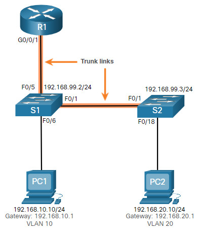
The VLAN and IPv4 addressing information for R1 is shown in the table.
Router R1 Subinterfaces
| Subinterface | VLAN | IP Address |
|---|---|---|
| G0/0/0.10 | 10 | 192.168.10.1/24 |
| G0/0/0.20 | 20 | 192.168.20.1/24 |
| G0/0/0.30 | 99 | 192.168.99.1/24 |
4.4.3 Missing VLANs
An inter-VLAN connectivity issue could be caused by a missing VLAN. The VLAN could be missing if it was not created, it was accidently deleted, or it is not allowed on the trunk link.
For example, PC1 is currently connected to VLAN 10, as shown in the show vlan brief command output.
S1# show vlan brief
VLAN Name                             Status    Ports
---- -------------------------------- --------- -------------------------------
1    default                          active    Fa0/2, Fa0/3, Fa0/4, Fa0/7
                                                Fa0/8, Fa0/9, Fa0/10, Fa0/11
                                                Fa0/12, Fa0/13, Fa0/14, Fa0/15
                                                Fa0/16, Fa0/17, Fa0/18, Fa0/19
                                                Fa0/20, Fa0/21, Fa0/22, Fa0/23
                                                Fa0/24, Gi0/1, Gi0/2
10   LAN10                            active    Fa0/6
20   LAN20                            active
99   Management                       active
1002 fddi-default                     act/unsup
1003 token-ring-default               act/unsup
1004 fddinet-default                  act/unsup
1005 trnet-default                    act/unsup
S1#
Now assume that VLAN 10 is accidently deleted, as shown in the following output.
S1(config)# no vlan 10
S1(config)# do show vlan brief
VLAN Name                             Status    Ports
---- -------------------------------- --------- -------------------------------
1    default                          active    Fa0/2, Fa0/3, Fa0/4, Fa0/7
                                                Fa0/8, Fa0/9, Fa0/10, Fa0/11
                                                Fa0/12, Fa0/13, Fa0/14, Fa0/15
                                                Fa0/16, Fa0/17, Fa0/18, Fa0/19
                                                Fa0/20, Fa0/21, Fa0/22, Fa0/23
                                                Fa0/24, Gi0/1, Gi0/2
20   LAN20                            active
99   Management                       active
1002 fddi-default                     act/unsup
1003 token-ring-default               act/unsup
1004 fddinet-default                  act/unsup
1005 trnet-default                    act/unsup
S1(config)#
Notice VLAN 10 is now missing from the output. Also notice that port Fa0/6 has not been reassigned to the default VLAN. The reason is because when you delete a VLAN, any ports assigned to that VLAN become inactive. They remain associated with the VLAN (and thus inactive) until you assign them to a new VLAN or recreate the missing VLAN.
Use the show interface interface-id switchport command to verify the VLAN membership.
S1(config)# do show interface fa0/6 switchport
Name: Fa0/6
Switchport: Enabled
Administrative Mode: static access
Operational Mode: static access
Administrative Trunking Encapsulation: dot1q
Operational Trunking Encapsulation: native
Negotiation of Trunking: Off
Access Mode VLAN: 10 (Inactive)
Trunking Native Mode VLAN: 1 (default)
Administrative Native VLAN tagging: enabled
Voice VLAN: none
(Output omitted)
Recreating the missing VLAN would automatically reassign the hosts to it, as shown in the following output.
S1(config)# vlan 10
S1(config-vlan)# do show vlan brief
VLAN Name                             Status    Ports
---- -------------------------------- --------- -------------------------------
1    default                          active    Fa0/2, Fa0/3, Fa0/4, Fa0/7
                                                Fa0/8, Fa0/9, Fa0/10, Fa0/11
                                                Fa0/12, Fa0/13, Fa0/14, Fa0/15
                                                Fa0/16, Fa0/17, Fa0/18, Fa0/19
                                                Fa0/20, Fa0/21, Fa0/22, Fa0/23
                                                Fa0/24, Gi0/1, Gi0/2
20   LAN20                            active
99   Management                       active
1002 fddi-default                     act/unsup
1003 token-ring-default               act/unsup
1004 fddinet-default                  act/unsup
1005 trnet-default                    act/unsup
S1(config-vlan)#
Notice that the VLAN has not been created as expected. The reason is because you must exit from VLAN sub-configuration mode to create the VLAN, as shown in the following output.
S1(config-vlan)# exit
S1(config)# do show vlan brief
VLAN Name                             Status    Ports
---- -------------------------------- --------- -------------------------------
1    default                          active    Fa0/2, Fa0/3, Fa0/4, Fa0/7
                                                Fa0/8, Fa0/9, Fa0/10, Fa0/11
                                                Fa0/12, Fa0/13, Fa0/14, Fa0/15
                                                Fa0/16, Fa0/17, Fa0/18, Fa0/19
                                                Fa0/20, Fa0/21, Fa0/22, Fa0/23
                                                Fa0/24, Gi0/1, Gi0/2
10   VLAN0010                         active    Fa0/6
20   LAN20                            active
99   Management                       active
1002 fddi-default                     act/unsup
1003 token-ring-default               act/unsup
1004 fddinet-default                  act/unsup
1005 trnet-default                    act/unsup
S1(config)#
Now notice that the VLAN is included in the list and that the host connected to Fa0/6 is on VLAN 10.
4.4.4 Switch Trunk Port Issues
Another issue for inter-VLAN routing includes misconfigured switch ports. In a legacy inter-VLAN solution, this could be caused when the connecting router port is not assigned to the correct VLAN.
However, with a router-on-a-stick solution, the most common cause is a misconfigured trunk port.
For example, assume PC1 was able to connect to hosts in other VLANs until recently. A quick look at maintenance logs revealed that the S1 Layer 2 switch was recently accessed for routine maintenance. Therefore, you suspect the problem may be related to that switch.
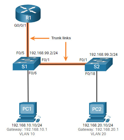
On S1, verify that the port connecting to R1 (i.e., F0/5) is correctly configured as a trunk link using the show interfaces trunk command, as shown.
S1# show interfaces trunk
Port        Mode             Encapsulation  Status        Native vlan
Fa0/1       on               802.1q         trunking      1
Port        Vlans allowed on trunk
Fa0/1       1-4094
Port        Vlans allowed and active in management domain
Fa0/1       1,10,20,99
Port        Vlans in spanning tree forwarding state and not pruned
Fa0/1       1,10,20,99
S1#
The Fa0/5 port connecting to R1 is mysteriously missing from the output. Verify the interface configuration using the show running-config interface fa0/5 command, as shown.
S1# show running-config interface fa0/5
Building configuration...
Current configuration : 96 bytes
!
interface FastEthernet0/5
 description Trunk link to R1
 switchport mode trunk
 shutdown
end
S1#
As you can see, the port was accidently shut down. To correct the problem, re-enable the port and verify the trunking status, as shown in the output.
S1(config)# interface fa0/5
S1(config-if)# no shut
S1(config-if)#
*Mar  1 04:46:44.153: %LINK-3-UPDOWN: Interface FastEthernet0/5, changed state to up
S1(config-if)#
*Mar  1 04:46:47.962: %LINEPROTO-5-UPDOWN: Line protocol on Interface FastEthernet0/5, changed state to up
S1(config-if)# do show interface trunk
Port        Mode             Encapsulation  Status        Native vlan
Fa0/1       on               802.1q         trunking      1
Fa0/5       on               802.1q         trunking      1
Port        Vlans allowed on trunk
Fa0/1       1-4094
Fa0/5       1-4094
Port        Vlans allowed and active in management domain
Fa0/1       1,10,20,99
Fa0/5       1,10,20,99
Port        Vlans in spanning tree forwarding state and not pruned
Fa0/1       1,10,20,99
Fa0/1       1,10,20,99
S1(config-if)#
To reduce the risk of a failed inter-switch link disrupting inter-VLAN routing, redundant links and alternate paths should be part of the network design.
4.4.5 Switch Access Port Issues
When a problem is suspected with a switch access port configuration, use verification commands to examine the configuration and identify the problem.
Assume PC1 has the correct IPv4 address and default gateway but is not able to ping its own default gateway. PC1 is supposed to be connected to a VLAN 10 port.
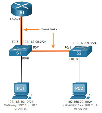
Verify the port configuration on S1 using the show interfaces interface-id switchport command.
S1# show interface fa0/6 switchport
Name: Fa0/6
Switchport: Enabled
Administrative Mode: static access
Operational Mode: static access
Administrative Trunking Encapsulation: dot1q
Operational Trunking Encapsulation: native
Negotiation of Trunking: Off
Access Mode VLAN: 1 (default)
Trunking Native Mode VLAN: 1 (default)
Administrative Native VLAN tagging: enabled
Voice VLAN: none
The Fa0/6 port has been configured as an access port as indicated by “static access”. However, it appears that it has not been configured to be in VLAN 10. Verify the configuration of the interface.
S1# show running-config interface fa0/6
Building configuration...
Current configuration : 87 bytes
!
interface FastEthernet0/6
 description PC-A access port
 switchport mode access
end
S1#
Assign port Fa0/6 to VLAN 10 and verify the port assignment.
S1# configure terminal
S1(config)# interface fa0/6
S1(config-if)# switchport access vlan 10
S1(config-if)#
S1(config-if)# do show interface fa0/6 switchport
Name: Fa0/6
Switchport: Enabled
Administrative Mode: static access
Operational Mode: static access
Administrative Trunking Encapsulation: dot1q
Operational Trunking Encapsulation: native
Negotiation of Trunking: Off
Access Mode VLAN: 10 (VLAN0010)
Trunking Native Mode VLAN: 1 (default)
Administrative Native VLAN tagging: enabled
Voice VLAN: none
(Output omitted)
PC1 is now able to communicate with hosts on other VLANs.
4.4.6 Router Configuration Issues
Router-on-a-stick configuration problems are usually related to subinterface misconfigurations. For example, an incorrect IP address was configured or the wrong VLAN ID was assigned to the subinterface.
For example, R1 should be providing inter-VLAN routing for users in VLANs 10, 20, and 99. However, users in VLAN 10 cannot reach any other VLAN.
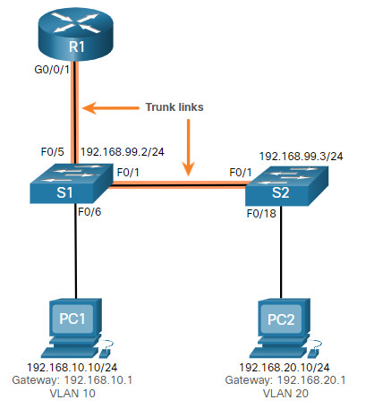
You verified the switch trunk link and all appears to be in order. Verify the subinterface status using the show ip interface brief command.
R1# show ip interface brief
Interface              IP-Address      OK? Method Status                Protocol
GigabitEthernet0/0/0   unassigned      YES unset  administratively down down
GigabitEthernet0/0/1   unassigned      YES unset  up                    up
Gi0/0/1.10             192.168.10.1    YES manual up                    up
Gi0/0/1.20             192.168.20.1    YES manual up                    up
Gi0/0/1.99             192.168.99.1    YES manual up                    up
Serial0/1/0            unassigned      YES unset  administratively down down
Serial0/1/1            unassigned      YES unset  administratively down down
R1#
The subinterfaces have been assigned the correct IPv4 addresses and they are operational.
Verify which VLANs each of the subinterfaces is on. To do so, the show interfaces command is useful but it generates a great deal of additional unrequired output. The command output can be reduced using IOS command filters as shown in the output.
R1# show interfaces | include Gig|802.1Q
GigabitEthernet0/0/0 is administratively down, line protocol is down
GigabitEthernet0/0/1 is up, line protocol is up
  Encapsulation 802.1Q Virtual LAN, Vlan ID  1., loopback not set
GigabitEthernet0/0/1.10 is up, line protocol is up
  Encapsulation 802.1Q Virtual LAN, Vlan ID  100.
GigabitEthernet0/0/1.20 is up, line protocol is up
  Encapsulation 802.1Q Virtual LAN, Vlan ID  20.
GigabitEthernet0/0/1.99 is up, line protocol is up
  Encapsulation 802.1Q Virtual LAN, Vlan ID  99.
R1#
The pipe symbol (|) along with some select keywords is a useful method to help filter command output. In this example, the keyword include was used to identify that only lines containing the letters “Gig” or “802.1Q” will be displayed. Because of the way the show interface output is naturally listed, using these filters produces a condensed list of interfaces and their assigned VLANs.
Notice that the G0/0/1.10 interface has been incorrectly assigned to VLAN 100 instead of VLAN 10. This is confirmed by looking at the configuration of the R1 GigabitEthernet 0/0/1.10 subinterface, as shown.
R1# show running-config interface g0/0/1.10
Building configuration...
Current configuration : 146 bytes
!
interface GigabitEthernet0/0/1.10
 description Default Gateway for VLAN 10
 encapsulation dot1Q 100
 ip address 192.168.10.1 255.255.255.0
end
R1#
To correct this problem, configure subinterface G0/0/1.10 to be on the correct VLAN using the encapsulation dot1q 10 subinterface configuration mode command.
R1# conf t
Enter configuration commands, one per line.  End with CNTL/Z.
R1(config)# interface gigabitEthernet 0/0/1.10
R1(config-subif)# encapsulation dot1Q 10
R1(config-subif)# end
R1#
R1# show interfaces | include Gig|802.1Q
GigabitEthernet0/0/0 is administratively down, line protocol is down
GigabitEthernet0/0/1 is up, line protocol is up
  Encapsulation 802.1Q Virtual LAN, Vlan ID  1., loopback not set
GigabitEthernet0/0/1.10 is up, line protocol is up
  Encapsulation 802.1Q Virtual LAN, Vlan ID  10.
GigabitEthernet0/0/1.20 is up, line protocol is up
  Encapsulation 802.1Q Virtual LAN, Vlan ID  20.
GigabitEthernet0/0/1.99 is up, line protocol is up
R1#
When the subinterface has been assigned to the correct VLAN, it is accessible by devices on that VLAN and the router can perform inter-VLAN routing.
With verification, router configuration problems are quickly addressed, allowing inter-VLAN routing to function properly.
4.4.8 Packet Tracer – Troubleshoot Inter-VLAN Routing
In this Packet Tracer activity, you will complete the following objectives:
- Part 1: Locate Network Problems
- Part 2: Implement the Solution
- Part 3: Verify Network Connectivity
4.4.8 Packet Tracer – Troubleshoot Inter-VLAN Routing
4.4.9 Lab – Troubleshoot Inter-VLAN Routing
Skills Practice Opportunity
In this lab, you will complete the following objectives:
- Part 1: Evaluate Network Operation
- Part 2: Gather Information, Create an Action Plan, and Implement Corrections
You can practice these skills using the Packet Tracer or lab equipment, if available.
Packet Tracer – Physical Mode (PTPM)
4.4.9 Packet Tracer – Troubleshoot Inter-VLAN Routing – Physical Mode
Lab Equipment
4.4.9 Lab – Troubleshoot Inter-VLAN Routing
4.5 Module Practice and Quiz
4.5.1 Packet Tracer – Inter-VLAN Routing Challenge
In this activity, you will demonstrate and reinforce your ability to implement inter-VLAN routing, including configuring IP addresses, VLANs, trunking, and subinterfaces.
4.5.1 Packet Tracer – Inter-VLAN Routing Challenge
4.5.2 Lab – Implement Inter-VLAN Routing
In this lab, you will complete the following objectives:
- Part 1: Build the Network and Configure Basic Device Settings
- Part 2: Create VLANs and Assign Switch Ports
- Part 3: Configure an 802.1Q Trunk between the Switches
- Part 4: Configure Inter-VLAN Routing on the S1 Switch
- Part 5: Verify Inter-VLAN Routing is Working
4.5.2 Lab – Implement Inter-VLAN Routing
4.5.3 What did I learn in this module?
Inter-VLAN Routing Operation
Hosts in one VLAN cannot communicate with hosts in another VLAN unless there is a router or a Layer 3 switch to provide routing services. Inter-VLAN routing is the process of forwarding network traffic from one VLAN to another VLAN. Three options include legacy, router-on-a-stick, and Layer 3 switch using SVIs. Legacy used a router with multiple Ethernet interfaces. Each router interface was connected to a switch port in different VLANs. Requiring one physical router interface per VLAN quickly exhausts the physical interface capacity of a router. The ‘router-on-a-stick’ inter-VLAN routing method only requires one physical Ethernet interface to route traffic between multiple VLANs on a network. A Cisco IOS router Ethernet interface is configured as an 802.1Q trunk and connected to a trunk port on a Layer 2 switch. The router interface is configured using subinterfaces to identify routable VLANs. The configured subinterfaces are software-based virtual interfaces, associated with a single physical Ethernet interface. The modern method is Inter-VLAN routing on a Layer 3 switch using SVIs. The SVI is created for a VLAN that exists on the switch. The SVI performs the same functions for the VLAN as a router interface. It provides Layer 3 processing for packets being sent to or from all switch ports associated with that VLAN.
Router-on-a-Stick Inter-VLAN Routing
To configure a switch with VLANs and trunking, complete the following steps: create and name the VLANs, create the management interface, configure access ports, and configure trunking ports. The router-on-a-stick method requires a subinterface to be created for each VLAN to be routed. A subinterface is created using the interface interface_id subinterface_id global configuration mode command. Each router subinterface must be assigned an IP address on a unique subnet for routing to occur. When all subinterfaces have been created, the physical interface must be enabled using the no shutdown interface configuration command. From a host, verify connectivity to a host in another VLAN using the ping command. Use ping to verify connectivity with the host and the switch. To verify and troubleshoot use the show ip route, show ip interface brief, show interfaces, and show interfaces trunk commands.
Inter-VLAN Routing using Layer 3 Switches
Enterprise campus LANs use Layer 3 switches to provide inter-VLAN routing. Layer 3 switches use hardware-based switching to achieve higher-packet processing rates than routers. Capabilities of a Layer 3 switch include routing from one VLAN to another using multiple switched virtual interfaces (SVIs) and converting a Layer 2 switchport to a Layer 3 interface (i.e., a routed port). To provide inter-VLAN routing, Layer 3 switches use SVIs. SVIs are configured using the same interface vlan vlan-id command used to create the management SVI on a Layer 2 switch. A Layer 3 SVI must be created for each of the routable VLANs. To configure a switch with VLANS and trunking, complete the following steps: create the VLANS, create the SVI VLAN interfaces, configure access ports, and enable IP routing. From a host, verify connectivity to a host in another VLAN using the ping command. Next, verify connectivity with the host using the ping Windows host command. VLANs must be advertised using static or dynamic routing. To enable routing on a Layer 3 switch, a routed port must be configured. A routed port is created on a Layer 3 switch by disabling the switchport feature on a Layer 2 port that is connected to another Layer 3 device. The interface can be configured with an IPv4 configuration to connect to a router or another Layer 3 switch. To configure a Layer 3 switch to route with a router, follow these steps: configure the routed port, enable routing, configure routing, verify routing, and verify connectivity.
Troubleshoot Inter-VLAN Routing
There are a number of reasons why an inter-VAN configuration may not work. All are related to connectivity issues such as missing VLANs, switch trunk port issues, switch access port issues, and router configuration issues. A VLAN could be missing if it was not created, it was accidently deleted, or it is not allowed on the trunk link. Another issue for inter-VLAN routing includes misconfigured switch ports. In a legacy inter-VLAN solution, a misconfigured switch port could be caused when the connecting router port is not assigned to the correct VLAN. With a router-on-a-stick solution, the most common cause is a misconfigured trunk port. When a problem is suspected with a switch access port configuration, use ping and show interfaces interface-id switchport commands to identify the problem. Router configuration problems with router-on-a-stick configurations are usually related to subinterface misconfigurations. Verify the subinterface status using the show ip interface brief command.
