12.0 Introduction
12.0.1 Why Should I Take this Module?
With the many threats to network security, how can networks be designed to protect data resources and ensure that network services are provided as required? The network security infrastructure defines the way in which devices are connected together to achieve end-to-end secure communications. Just as there are many sizes of networks, there are also many ways to build a secure network infrastructure. However, there are some standard designs that the network industry recommends achieving networks that are available and secure. This chapter covers the basic operation of network infrastructures, the various network security devices, and the security services that are used to monitor and maintain the safe and efficient transmission of data.
12.0.2 What Will I Learn in this Module?
Module Title: Network Security Infrastructure
Module Objective: Explain how devices and services are used to enhance network security.
| Topic Title | Topic Objective |
|---|---|
| Network Topologies | Explain how network designs influence the flow of traffic through the network. |
| Security Devices | Explain how specialized devices are used to enhance network security. |
| Security Services | Explain how network services enhance network security. |
12.1 Network Topologies
12.1.1 Network Representations
Network architects and administrators must be able to show what their networks will look like. They need to be able to easily see which components connect to other components, where they will be located, and how they will be connected. Diagrams of networks often use symbols, like those shown in the figure, to represent the different devices and connections that make up a network.
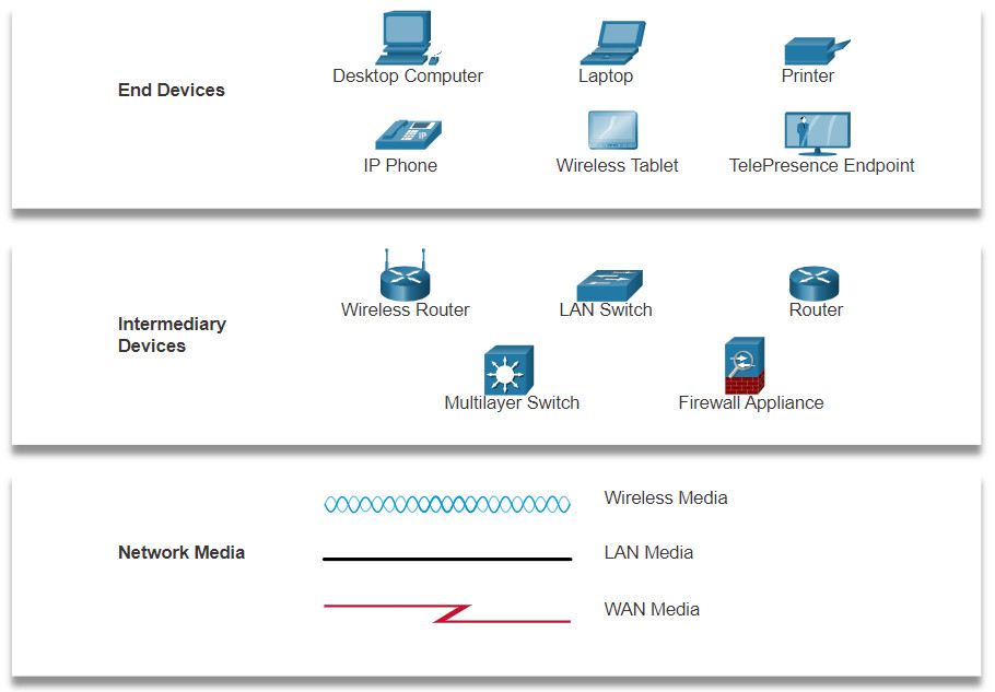
A diagram provides an easy way to understand how devices connect in a large network. This type of “picture” of a network is known as a topology diagram. The ability to recognize the logical representations of the physical networking components is critical to being able to visualize the organization and operation of a network.
In addition to these representations, specialized terminology is used to describe how each of these devices and media connect to each other:
- Network Interface Card (NIC) – A NIC physically connects the end device to the network.
- Physical Port – A connector or outlet on a networking device where the media connects to an end device or another networking device.
- Interface – Specialized ports on a networking device that connect to individual networks. Because routers connect networks, the ports on a router are referred to as network interfaces.
Note: The terms port and interface are often used interchangeably.
12.1.2 Topology Diagrams
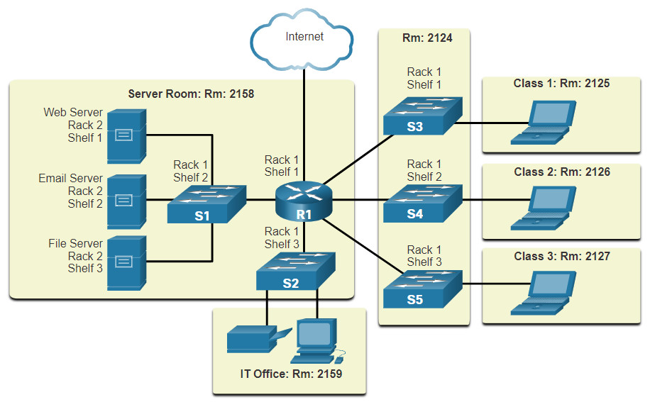
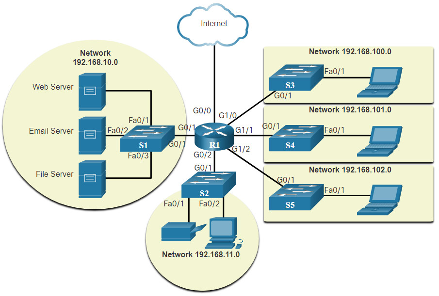
Topology diagrams are mandatory documentation for anyone working with a network. They provide a visual map of how the network is connected. There are two types of topology diagrams: physical and logical.
Physical Topology Diagrams
Physical topology diagrams illustrate the physical location of intermediary devices and cable installation, as shown in the figure. You can see that the rooms in which these devices are located are labeled in this physical topology.
Logical Topology Diagrams
Logical topology diagrams illustrate devices, ports, and the addressing scheme of the network, as shown in the figure. You can see which end devices are connected to which intermediary devices and what media is being used.
The topologies shown in the physical and logical diagrams are appropriate for your level of understanding at this point in the course. Search the internet for “network topology diagrams” to see some more complex examples. If you add the word “Cisco” to your search phrase, you will find many topologies using icons that are similar to what you have seen in these figures.
12.1.3 Networks of Many Sizes
Now that you are familiar with the components that make up networks and their representations in physical and logical topologies, you are ready to learn about the many different types of networks.
Networks come in all sizes. They range from simple networks consisting of two computers, to networks connecting millions of devices.
Simple home networks let you share resources, such as printers, documents, pictures, and music, among a few local end devices.
Small office and home office (SOHO) networks allow people to work from home, or a remote office. Many self-employed workers use these types of networks to advertise and sell products, order supplies, and communicate with customers.
Businesses and large organizations use networks to provide consolidation, storage, and access to information on network servers. Networks provide email, instant messaging, and collaboration among employees. Many organizations use their network’s connection to the internet to provide products and services to customers.
The internet is the largest network in existence. In fact, the term internet means a “network of networks”. It is a collection of interconnected private and public networks.
In small businesses and homes, many computers function as both the servers and clients on the network. This type of network is called a peer-to-peer network.
12.1.4 LANs and WANs
Network infrastructures vary greatly in terms of:
- Size of the area covered
- Number of users connected
- Number and types of services available
- Area of responsibility
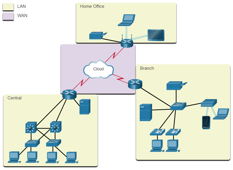
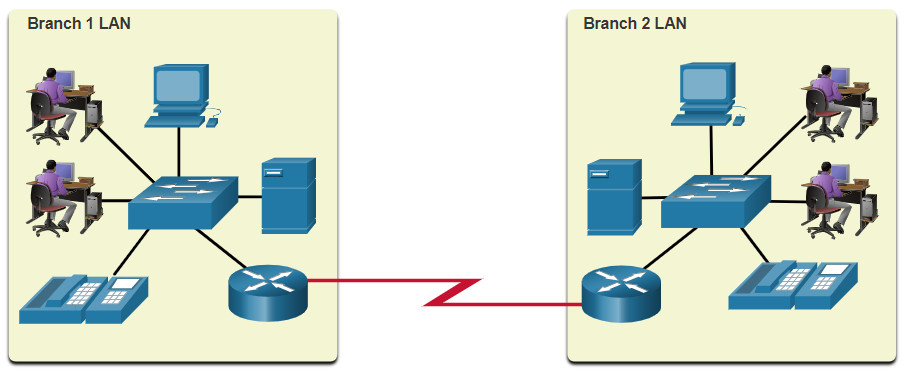
The two most common types of network infrastructures are Local Area Networks (LANs), and Wide Area Networks (WANs). A LAN is a network infrastructure that provides access to users and end devices in a small geographical area. A LAN is typically used in a department within an enterprise, a home, or a small business network. A WAN is a network infrastructure that provides access to other networks over a wide geographical area, which is typically owned and managed by a larger corporation or a telecommunications service provider. The figure shows LANs connected to a WAN.
LANs
A LAN is a network infrastructure that spans a small geographical area. LANs have specific characteristics:
- LANs interconnect end devices in a limited area such as a home, school, office building, or campus.
- A LAN is usually administered by a single organization or individual. Administrative control is enforced at the network level and governs the security and access control policies.
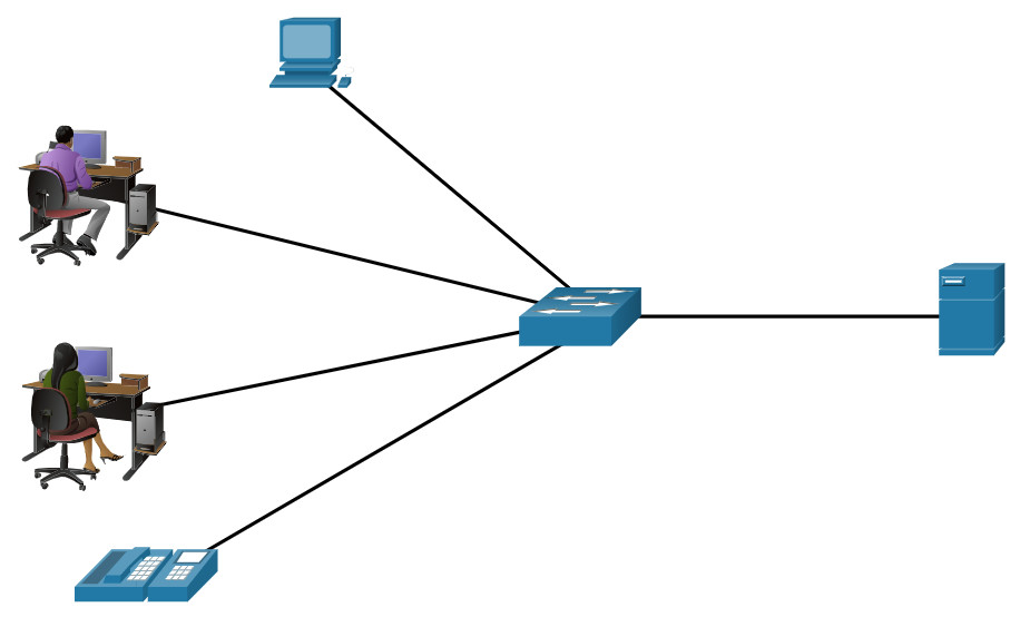
- LANs provide high-speed bandwidth to internal end devices and intermediary devices, as shown in the figure.
A network serving a home, small building, or a small campus is considered a LAN.
WANs
The figure shows a WAN which interconnects two LANs. A WAN is a network infrastructure that spans a wide geographical area. WANs are typically managed by service providers (SPs) or Internet Service Providers (ISPs).
WANs have specific characteristics:
- WANs interconnect LANs over wide geographical areas such as between cities, states, provinces, countries, or continents.
- WANs are usually administered by multiple service providers.
- WANs typically provide slower speed links between LANs.
12.1.5 The Three-Layer Network Design Model
The campus wired LAN uses a hierarchical design model to separate the network topology into modular groups or layers. Separating the design into layers allows each layer to implement specific functions, which simplifies the network design. This also simplifies the deployment and management of the network.
The campus wired LAN enables communications between devices in a building or group of buildings, as well as interconnection to the WAN and Internet edge at the network core.
A hierarchical LAN design includes the access, distribution, and core layers as shown in the figure.
Hierarchical Design Model
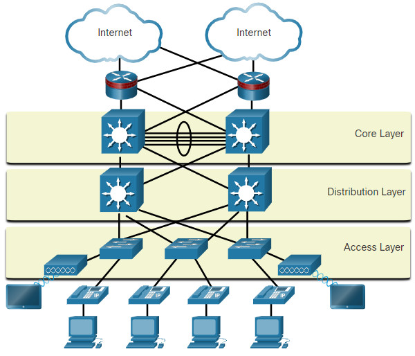
Each layer is designed to meet specific functions.
The access layer provides endpoints and users direct access to the network. The distribution layer aggregates access layers and provides connectivity to services. Finally, the core layer provides connectivity between distribution layers for large LAN environments. User traffic is initiated at the access layer and passes through the other layers if the functionality of those layers is required.
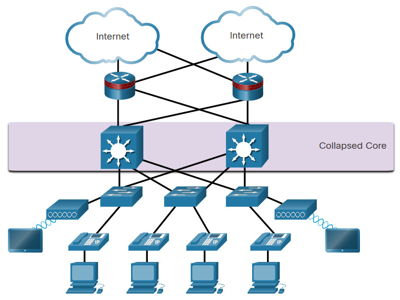
Even though the hierarchical model has three layers, some smaller enterprise networks may implement a two-tier hierarchical design. In a two-tier hierarchical design, the core and distribution layers are collapsed into one layer, reducing cost and complexity, as shown in the figure.
Collapsed Core
In flat or meshed network architectures, changes tend to affect a large number of systems. Hierarchical design helps constrain operational changes to a subset of the network, which makes it easy to manage as well as improve resiliency. Modular structuring of the network into small, easy-to-understand elements also facilitates resiliency through improved fault isolation.
12.1.6 Video – Three-Layer Network Design
Watch this video to learn about the three-layer network design model.
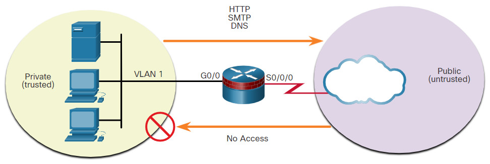
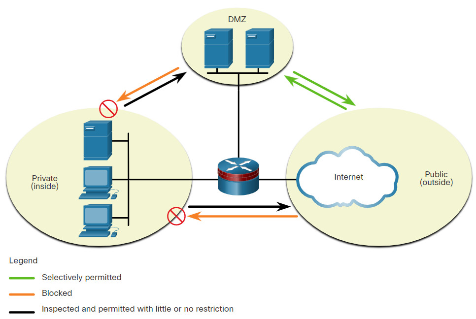
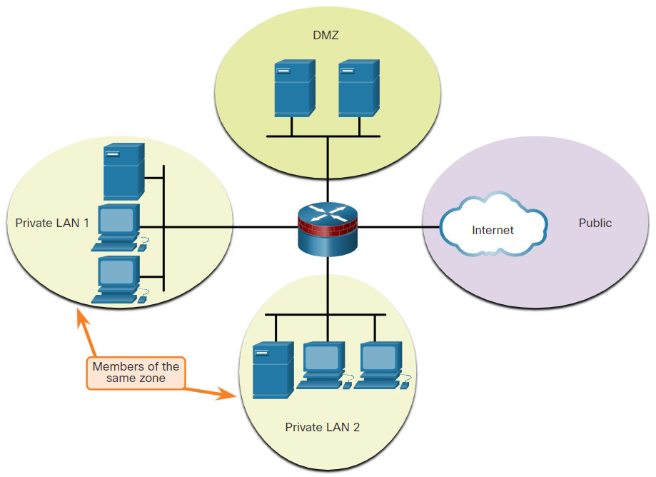
12.1.7 Common Security Architectures
Firewall design is primarily about device interfaces permitting or denying traffic based on the source, the destination, and the type of traffic. Some designs are as simple as designating an outside network and inside network, which are determined by two interfaces on a firewall.
Here are three common firewall designs.
12.1.9 Packet Tracer – Identify Packet Flow
In this Packet Tracer activity, you will observe packet flow in a LAN and WAN topology. You will also observe how the packet flow path may change when there is a change in the network topology
12.2 Security Devices
12.2.1 Video – Security Devices
Play the video to learn more about security services.
12.2.2 Firewalls
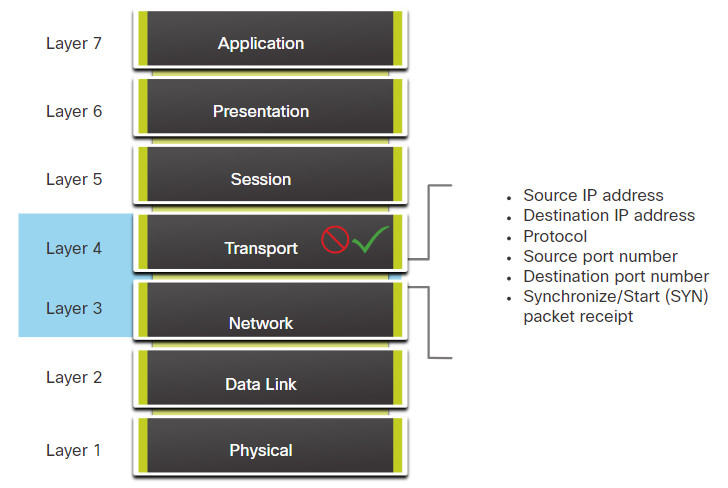
A firewall is a system, or group of systems, that enforces an access control policy between networks.
Play the animation in the figure to view a firewall in operation.
Firewall Operation

Click each button to learn more about firewalls.
12.2.3 Firewall Type Descriptions
It is important to understand the different types of firewalls and their specific capabilities so that the right firewall is used for each situation.
Other methods of implementing firewalls include:
- Host-based (server and personal) firewall – A PC or server with firewall software running on it.
- Transparent firewall – Filters IP traffic between a pair of bridged interfaces.
- Hybrid firewall – A combination of the various firewall types. For example, an application inspection firewall combines a stateful firewall with an application gateway firewall.
12.2.5 Intrusion Prevention and Detection Devices
A networking architecture paradigm shift is required to defend against fast-moving and evolving attacks. This must include cost-effective detection and prevention systems, such as intrusion detection systems (IDS) or the more scalable intrusion prevention systems (IPS). The network architecture integrates these solutions into the entry and exit points of the network.
When implementing IDS or IPS, it is important to be familiar with the types of systems available, host-based and network-based approaches, the placement of these systems, the role of signature categories, and possible actions that a Cisco IOS router can take when an attack is detected.
The figure shows how an IPS device handles malicious traffic.
IDS and IPS Characteristics
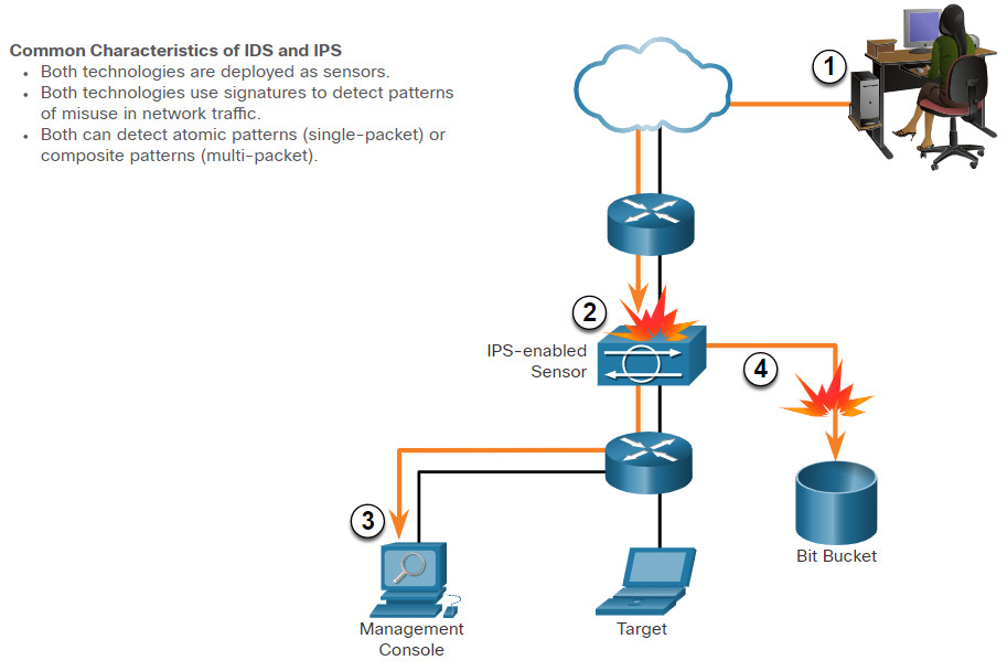
- Malicious traffic is sent to the target host that is inside the network.
- The traffic is routed into the network and received by an IPS-enabled sensor where it is blocked.
- The IPS-enabled sensor sends logging information regarding the traffic to the network security management console.
- The IPS-enabled sensor kills the traffic. (It is sent to the “Bit Bucket.”)
IDS and IPS technologies are both deployed as sensors. An IDS or IPS sensor can be in the form of several different devices:
- A router configured with Cisco IOS IPS software
- A device specifically designed to provide dedicated IDS or IPS services
- A network module installed in an adaptive security appliance (ASA), switch, or router
IDS and IPS technologies use signatures to detect patterns in network traffic. A signature is a set of rules that an IDS or IPS uses to detect malicious activity. Signatures can be used to detect severe breaches of security, to detect common network attacks, and to gather information. IDS and IPS technologies can detect atomic signature patterns (single-packet) or composite signature patterns (multi-packet).
12.2.6 Advantages and Disadvantages of IDS and IPS
IDS Advantages and Disadvantages
The table lists the advantages and disadvantages of IDS and IPS.
| Solution | Advantages | Disadvantages |
|---|---|---|
| IDS |
|
|
| IPS |
|
|
Click on each button to learn more about IDS and IPS sensors.
12.2.7 Types of IPS
There are two primary kinds of IPS available: host-based IPS and network-based IPS.
Host-based IPS
Host-based IPS (HIPS) is software installed on a host to monitor and analyze suspicious activity. A significant advantage of HIPS is that it can monitor and protect operating system and critical system processes that are specific to that host. With detailed knowledge of the operating system, HIPS can monitor abnormal activity and prevent the host from executing commands that do not match typical behavior. This suspicious or malicious behavior might include unauthorized registry updates, changes to the system directory, executing installation programs, and activities that cause buffer overflows. Network traffic can also be monitored to prevent the host from participating in a denial-of-service (DoS) attack or being part of an illicit FTP session.
HIPS can be thought of as a combination of antivirus software, antimalware software, and a firewall. Combined with a network-based IPS, HIPS is an effective tool in providing additional protection for the host.
A disadvantage of HIPS is that it operates only at a local level. It does not have a complete view of the network, or coordinated events that might be happening across the network. To be effective in a network, HIPS must be installed on every host and have support for every operating system. The table lists the advantages and disadvantages of HIPS.
| Advantages | Disadvantages |
|---|---|
|
|
Network-based IPS
A network-based IPS can be implemented using a dedicated or non-dedicated IPS device. Network-based IPS implementations are a critical component of intrusion prevention. There are host-based IDS/IPS solutions, but these must be integrated with a network-based IPS implementation to ensure a robust security architecture.
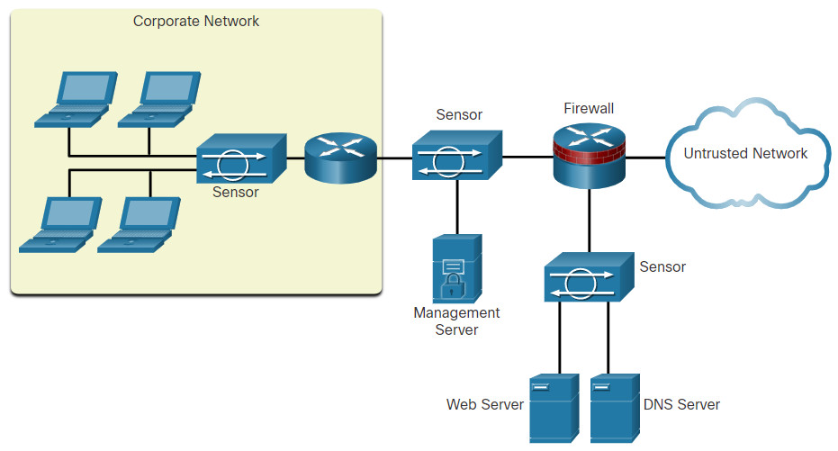
Sensors detect malicious and unauthorized activity in real time and can take action when required. As shown in the figure, sensors are deployed at designated network points. This enables security managers to monitor network activity while it is occurring, regardless of the location of the attack target.
Sample IPS Sensor Deployment
12.2.8 Specialized Security Appliances
There are a variety of specialized security appliances available. Here are a few examples.
12.3 Security Services
12.3.1 Video – Security Services
Watch the video to learn more about security services.
12.3.2 Traffic Control with ACLs
An Access Control List (ACL) is a series of commands that control whether a device forwards or drops packets based on information found in the packet header. When configured, ACLs perform the following tasks:
- They limit network traffic to increase network performance. For example, if corporate policy does not allow video traffic on the network, ACLs that block video traffic could be configured and applied. This would greatly reduce the network load and increase network performance.
- They provide traffic flow control. ACLs can restrict the delivery of routing updates to ensure that the updates are from a known source.
- They provide a basic level of security for network access. ACLs can allow one host to access a part of the network and prevent another host from accessing the same area. For example, access to the Human Resources network can be restricted to authorized users.
- They filter traffic based on traffic type. For example, an ACL can permit email traffic, but block all Telnet traffic.
- They screen hosts to permit or deny access to network services. ACLs can permit or deny a user to access file types, such as FTP or HTTP.
In addition to either permitting or denying traffic, ACLs can be used for selecting types of traffic to be analyzed, forwarded, or processed in other ways. For example, ACLs can be used to classify traffic to enable priority processing. This capability is similar to having a VIP pass at a concert or sporting event. The VIP pass gives selected guests privileges not offered to general admission ticket holders, such as priority entry or being able to enter a restricted area.
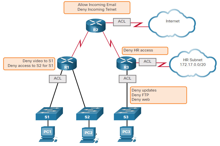
The figure shows a sample topology with ACLs applied to routers R1, R2, and R3.
What Is an ACL?
12.3.3 ACLs: Important Features
Two types of Cisco IPv4 ACLs are standard and extended. Standard ACLs can be used to permit or deny traffic only from source IPv4 addresses. The destination of the packet and the ports involved are not evaluated.
Extended ACLs filter IPv4 packets based on several attributes that include:
- Protocol type
- Source IPv4 address
- Destination IPv4 address
- Source TCP or UDP ports
- Destination TCP or UDP ports
- Optional protocol type information for finer control
Standard and extended ACLs can be created using either a number or a name to identify the ACL and its list of statements.
Using numbered ACLs is an effective method for determining the ACL type on smaller networks with more homogeneously defined traffic. However, a number does not provide information about the purpose of the ACL. For this reason, a name can be used to identify a Cisco ACL.
By configuring ACL logging, an ACL message can be generated and logged when traffic meets the permit or deny criteria defined in the ACL.
Cisco ACLs can also be configured to only allow TCP traffic that has an ACK or RST bit set, so that only traffic from an established TCP session is permitted. This can be used to deny any TCP traffic from outside the network that is trying to establish a new TCP session.
12.3.4 Packet Tracer – ACL Demonstration
In this activity, you will observe how an access control list (ACL) can be used to prevent a ping from reaching hosts on remote networks. After removing the ACL from the configuration, the pings will be successful.
12.3.5 SNMP
Simple Network Management Protocol (SNMP) allows administrators to manage end devices such as servers, workstations, routers, switches, and security appliances, on an IP network. It enables network administrators to monitor and manage network performance, find and solve network problems, and plan for network growth.
SNMP is an application layer protocol that provides a message format for communication between managers and agents.
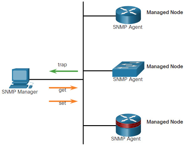
As shown in the figure, the SNMP system consists of two elements.
- SNMP manager that runs SNMP management software.
- SNMP agents which are the nodes being monitored and managed.
The Management Information Base (MIB) is a database on the agents that stores data and operational statistics about the device.
To configure SNMP on a networking device, it is first necessary to define the relationship between the manager and the agent.
The SNMP manager is part of a network management system (NMS). The SNMP manager runs SNMP management software. As shown in the figure, the SNMP manager can collect information from an SNMP agent by using the “get” action and can change configurations on an agent by using the “set” action. In addition, SNMP agents can forward information directly to a network manager by using “traps”.
12.3.6 NetFlow
NetFlow is a Cisco IOS technology that provides statistics on packets flowing through a Cisco router or multilayer switch. While SNMP attempts to provide a very wide range of network management features and options, NetFlow is focused on providing statistics on IP packets flowing through network devices.
NetFlow provides data to enable network and security monitoring, network planning, traffic analysis to include identification of network bottlenecks, and IP accounting for billing purposes. For example, in the figure, PC 1 connects to PC 2 using an application such as HTTPS.
NetFlow in the Network
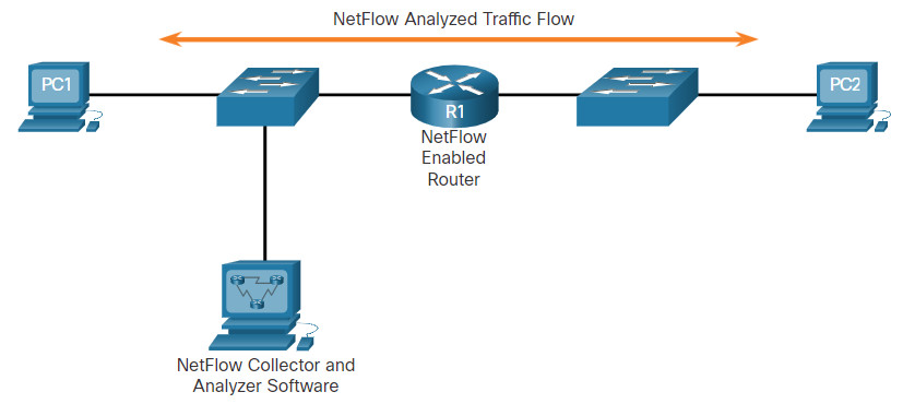
NetFlow can monitor that application connection, tracking byte and packet counts for that individual application flow. It then pushes the statistics over to an external server called a NetFlow collector.
NetFlow technology has seen several generations that provide more sophistication in defining traffic flows, but “original NetFlow” distinguished flows using a combination of seven fields. Should one of these fields vary in value from another packet, the packets could be safely determined to be from different flows:
- Source IP address
- Destination IP address
- Source port number
- Destination port number
- Layer 3 protocol type
- Type of Service (ToS) marking
- Input logical interface
The first four of the fields NetFlow uses to identify a flow should be familiar. The source and destination IP addresses, plus the source and destination ports, identify the connection between source and destination application. The Layer 3 protocol type identifies the type of header that follows the IP header (usually TCP or UDP, but other options include ICMP). The ToS byte in the IPv4 header holds information about how devices should apply quality of service (QoS) rules to the packets in that flow.
12.3.7 Port Mirroring
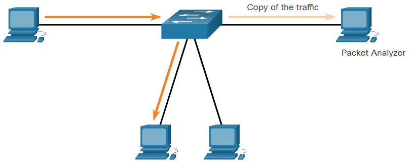
A packet analyzer (also known as a packet sniffer or traffic sniffer) is typically software that captures packets entering and exiting the network interface card (NIC). It is not always possible or desirable to have the packet analyzer on the device that is being monitored. Sometimes it is better on a separate station designated to capture the packets.
Because network switches can isolate traffic, traffic sniffers or other network monitors, such as IDS, cannot access all the traffic on a network segment. Port mirroring is a feature that allows a switch to make duplicate copies of traffic passing through a switch, and then send it out a port with a network monitor attached. The original traffic is forwarded in the usual manner. An example of port mirroring is illustrated in the figure.
Traffic Sniffing Using a Switch
12.3.8 Syslog Servers
When certain events occur on a network, networking devices have trusted mechanisms to notify the administrator with detailed system messages. These messages can be either non-critical or significant. Network administrators have a variety of options for storing, interpreting, and displaying these messages, and for being alerted to those messages that could have the greatest impact on the network infrastructure.
The most common method of accessing system messages is to use a protocol called syslog.
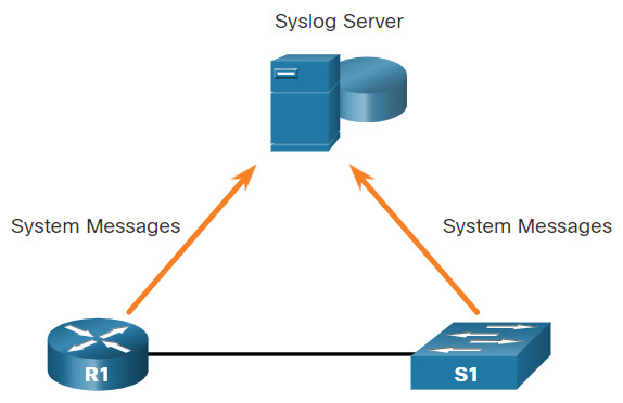
Many networking devices support syslog, including routers, switches, application servers, firewalls, and other network appliances. The syslog protocol allows networking devices to send their system messages across the network to syslog servers as shown in the figure.
Syslog
The syslog logging service provides three primary functions:
- The ability to gather logging information for monitoring and troubleshooting
- The ability to select the type of logging information that is captured
- The ability to specify the destination of captured syslog messages
12.3.9 NTP
It is important to synchronize the time across all devices on the network because all aspects of managing, securing, troubleshooting, and planning networks require accurate and consistent timestamping. When the time is not synchronized between devices, it will be impossible to determine the order of the events that have occurred in different parts of the network.
Typically, the date and time settings on a network device can be set using one of two methods:
- Manual configuration of the date and time
- Configuring the Network Time Protocol (NTP)
As a network grows, it becomes difficult to ensure that all infrastructure devices are operating with synchronized time. Even in a smaller network environment, the manual method is not ideal. If a device reboots, how will it get an accurate date and timestamp?
A better solution is to configure the NTP on the network. This protocol allows routers on the network to synchronize their time settings with an NTP server. A group of NTP clients that obtain time and date information from a single source have more consistent time settings. When NTP is implemented in the network, it can be set up to synchronize to a private master clock or it can synchronize to a publicly available NTP server on the Internet.
NTP networks use a hierarchical system of time sources. Each level in this hierarchical system is called a stratum. The stratum level is defined as the number of hop counts from the authoritative source. The synchronized time is distributed across the network using NTP. The figure displays a sample NTP network.
NTP Stratum Levels
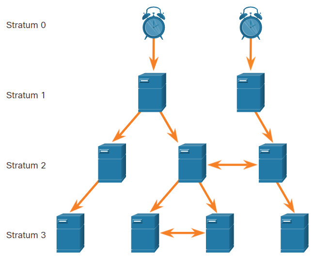
NTP servers are arranged in three levels known as strata:
- Stratum 0 – An NTP network gets the time from authoritative time sources. These authoritative time sources, also referred to as stratum 0 devices, are high-precision timekeeping devices assumed to be accurate and with little or no delay associated with them.
- Stratum 1 – The stratum 1 devices are directly connected to the authoritative time sources. They act as the primary network time standard.
- Stratum 2 and lower strata – The stratum 2 servers are connected to stratum 1 devices through network connections. Stratum 2 devices, such as NTP clients, synchronize their time using the NTP packets from stratum 1 servers. They could also act as servers for stratum 3 devices.
Smaller stratum numbers indicate that the server is closer to the authorized time source than larger stratum numbers. The larger the stratum number, the lower the stratum level. The max hop count is 15. Stratum 16, the lowest stratum level, indicates that a device is unsynchronized. Time servers on the same stratum level can be configured to act as a peer with other time servers on the same stratum level for backup or verification of time.
12.3.10 AAA Servers
The table lists the three independent security functions provided by the AAA architectural framework.
| AAA Provides | Description |
|---|---|
| Authentication |
|
| Authorization |
|
| Accounting |
|
Terminal Access Controller Access-Control System Plus (TACACS+) and Remote Authentication Dial-In User Service (RADIUS) are both authentication protocols that are used to communicate with AAA servers. Whether TACACS+ or RADIUS is selected depends on the needs of the organization.
While both protocols can be used to communicate between a router and AAA servers, TACACS+ is considered the more secure protocol. This is because all TACACS+ protocol exchanges are encrypted, while RADIUS only encrypts the user’s password. RADIUS does not encrypt usernames, accounting information, or any other information carried in the RADIUS message.
The table lists the differences between the two protocols.
| TACACS+ | RADIUS | |
|---|---|---|
| Functionality | Separates AAA according to the AAA architecture, allowing modularity of the security server implementation | Combines authentication and authorization but separates accounting, allowing less flexibility in implementation than TACACS+ |
| Standard | Mostly Cisco supported | Open/RFC standard |
| Transport | TCP | UDP |
| Protocol CHAP | Bidirectional challenge and response as used in Challenge Handshake Authentication Protocol (CHAP) | Unidirectional challenge and response from the RADIUS security server to the RADIUS client |
| Confidentiality | Entire packet encrypted | Password encrypted |
| Customization | Provides authorization of router commands on a per-user or per-group basis | Has no option to authorize router commands on a per-user or per-group basis |
| Accounting | Limited | Extensive |
12.3.11 VPN
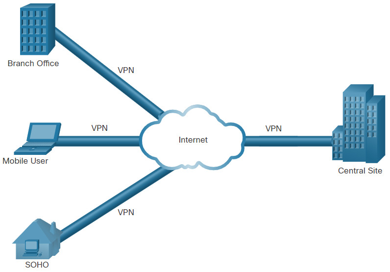
A VPN is a private network that is created over a public network, usually the internet, as shown in the figure.
Virtual Private Network
Instead of using a dedicated physical connection, a VPN uses virtual connections that are routed through the internet from the organization to the remote site. The first VPNs were strictly IP tunnels that did not include authentication or encryption of the data. For example, Generic Routing Encapsulation (GRE) is a tunneling protocol developed by Cisco that can encapsulate a wide variety of network layer protocol packet types inside IP tunnels. This creates a virtual point-to-point link to Cisco routers at remote points over an IP internetwork.
A VPN is virtual in that it carries information within a private network, but that information is actually transported over a public network. A VPN is private in that the traffic is encrypted to keep the data confidential while it is transported across the public network.
A VPN is a communications environment in which access is strictly controlled to permit peer connections within a defined community of interest. Confidentiality is achieved by encrypting the traffic within the VPN. Today, a secure implementation of VPN with encryption is what is generally equated with the concept of virtual private networking.
In the simplest sense, a VPN connects two endpoints, such as a remote office to a central office, over a public network, to form a logical connection. The logical connections can be made at either Layer 2 or Layer 3. Common examples of Layer 3 VPNs are GRE, Multiprotocol Label Switching (MPLS), and IPsec. Layer 3 VPNs can be point-to-point site connections, such as GRE and IPsec, or they can establish any-to-any connectivity to many sites using MPLS.
IPsec is a suite of protocols developed with the backing of the IETF to achieve secure services over IP packet-switched networks.
IPsec services allow for authentication, integrity, access control, and confidentiality. With IPsec, the information exchanged between remote sites can be encrypted and verified. VPNs are commonly deployed in a site-to-site topology to securely connect central sites with remote locations. They are also deployed in a remote-access topology to provide secure remote access to external users travelling or working from home. Both remote-access and site-to-site VPNs can be deployed using IPsec.
12.4 Network Security Infrastructure Summary
12.4.1 What Did I Learn in this Module?
Network Topologies
In this chapter, you learned the basic operation of the network infrastructure. Network infrastructures vary greatly depending on the size of the coverage area, the number of users connected, the number and types of services available, and the area of responsibility. Networks are typically represented as physical and logical topologies. A physical topology represents physical connections and how end devices are connected. A logical topology refers to the standards and protocols that devices use to communicate. Most topologies diagrams are a combination of both, showing how devices are physically and logically connected. The two most common types of network infrastructures are LANs and WANs. The campus wired LAN design consists of hierarchical layers with each layer assigned specific functions. The access layer provides direct access to the network for endpoints. The distribution layer aggregates access layers and provides connectivity to services. Lastly the core layer provides connectivity between distribution layers in large environments. In some cases, the distribution and core layers may be combined to reduce cost and complexity.
Common security architectures define the boundaries of traffic entering and leaving the network. When looking at a topology that has access to outside or public networks, you should be able to determine the security architecture. Some designs are as simple as designating an outside network and inside network which are determined by two interfaces on a firewall. Networks that require public access to services will often include a DMZ that the public can access, while strictly blocking access to the inside network. ZPFs use the concept of zones to provide additional flexibility. A zone is a group of one or more interfaces that have similar functions, features, and security requirements.
Security Devices
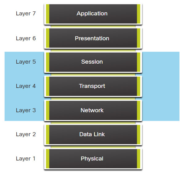
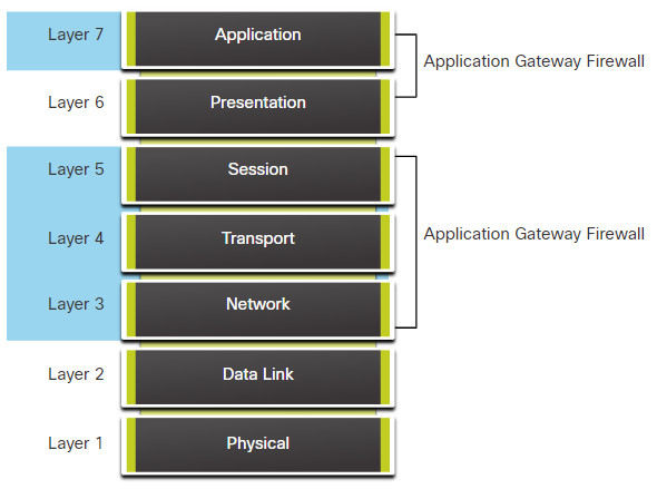
There are several different types of firewalls. Packet filtering (stateless) firewalls provide Layer 3 and sometimes Layer 4 filtering. A stateful inspection firewall allows or blocks traffic based on state, port, and protocol. Application gateway firewalls (proxy firewall) filter information at Layers 3, 4, 5, and 7. Next-generation firewalls provide additional services beyond application gateways such as Integrated intrusion prevention, application awareness and control to see and block risky apps, access to future information feeds, and techniques to address evolving security threats. Intrusion prevention systems (IPS) and intrusion detection systems (IDS) are used to detect potential security risks and alert/stop unsafe traffic. IDS/IPS can be implemented as host-based or network based with specific advantages and disadvantages to each implementation. Specialized security appliances are available including Cisco Advanced Malware Protection (AMP), Cisco Web Security Appliance (WSA), and Cisco Email Security Appliance (WSA). These security appliances utilize the services of the Cisco Talos Security Intelligence and Research Group. Talos detects and correlates threats in real time using the largest threat-detection network in the world.
Security Services
Network security services include the following technologies. ACLs are a series of statements that control whether a device forwards or drops packets based on information found in the packet header. SNMP enables network administrators to monitor and manage network performance, find and solve network problems, and plan for network growth. NetFlow provides statistics on packets that are flowing through a Cisco router or multilayer switch. Port mirroring is a feature that allows a switch to make duplicate copies of traffic that is passing through the switch, and then send it out a port that has a network monitor attached. Syslog servers compile and provide access to the system messages generated by networking devices. NTP synchronizes the system time across all devices on the network to ensure accurate and consistent timestamping of system messages. AAA is a framework for configuring user authentication, authorization, and accounting services. AAA typically uses a TACACS+ or RADIUS server for this purpose. VPNs are private networks that are created between two endpoints across a public network.


