2.0 – Introduction
2.0.1 – Introduction
2.0.1.1 – Welcome
Assembling computers is often a large part of an IT technician’s job. You must work in a logical, methodical manner when working with computer components. At times, you might have to determine whether a component for a customer’s computer needs to be upgraded or replaced. It is important that you develop skills in installation procedures, troubleshooting techniques, and diagnostic methods. This chapter discusses the importance of component compatibility. It also covers the need for adequate system resources to efficiently run the customer’s hardware and software. Computers, computer components, and computer peripherals all contain hazards that can cause severe injury. Therefore, this chapter begins with general and fire safety guidelines to follow when working with computer components.
In this chapter, you will learn about PC power supplies and the voltages they provide to other computer components. You will learn about the components that are installed on the motherboard; the CPU, RAM, and various adapter cards. You will learn about different CPU architectures and how to select RAM that is compatible with the motherboard and the chipset. You will also learn about various types of storage drives and the factors to consider when selecting the appropriate drive.
It is important to not only learn about assembling computer components but also to build hands-on skills. In this chapter there are several labs where you will assemble a computer. Each of the labs have you progressively install components such as the power supply, CPU, RAM, drives, adapter cards, and cables until computer assembly is complete.
2.1 – Assemble the Computer
2.1.1 – General and Fire Safety
2.1.1.1 – Video Explanation – General and Fire Safety
Download transcript of this video:
2.1.2 – Open the Case and Connect the Power Supply
2.1.2.1 – Video Demonstration – Install the Power Supply
Download transcript of this video:
2.1.2.2 – Check Your Understanding – Install the Power Supply
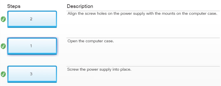
Check Your Understanding – Install the Power Supply
2.1.2.3 – Select the Case and Fans
The choice of motherboard and external components influences the selection of the case and power supply. The motherboard form factor must be matched with the correct type of computer case and power supply. For example, an ATX motherboard requires both an ATX-compatible case and power supply.
You can select a larger computer case to accommodate additional components that may be required in the future. Or you might select a smaller case that requires minimal space. In general, the computer case should be durable, easy to service, and have enough room for expansion.
Various factors affecting the choice of a computer case are described in Figure 1:
Model Type
The type of motherboard you choose determines the type of case that can be used. The size and shape must match exactly.
Size
If a computer has many components, it will need more room for airflow to keep the system cool.
Power Supply
You must match the power rating and connection type of the power supply to the type of motherboard you have chosen.
Appearance
For some people, how the case looks doesn’t matter at all. For others, it is critical. There are many case designs to choose from if it is necessary to have a case that is attractive.
Status Display
What is going on inside the case can be very important. LED indicators that are mounted on the outside of the case can tell you if the system is receiving power, when the hard drive is being used, and when the computer is in sleep or hibernate mode.
Vents
All cases have a vent on the power supply, and some have another vent on the back to help draw air into or out of the system. Some cases are designed with more vents in the event that the system needs a way to dissipate an unusual amount of heat. This situation may occur when many devices are installed close together in the case.
Cases often come with a power supply preinstalled. In this situation, you still need to verify that the power supply provides enough power to operate all the components that will be installed in the case.
A computer has many internal components that generate heat while the computer is running. Case fans should be installed to move cooler air into the computer case while moving heat out of the case. When choosing case fans, there are several factors to consider as described in Figure 2.
Note: The direction of air flow created by all the fans in the case must work together to inject cooler air and expel hotter air. Installing a fan backwards or using fans with the incorrect size or speed for the case can cause the air flows to work against each other.
Factors to Consider when Choosing a Case Fan
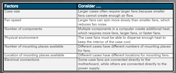
Factors to Consider when Choosing a Case Fan
2.1.2.4 – Select a Power Supply
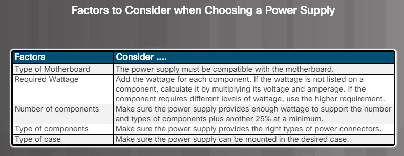
Power supplies convert AC input to DC output voltages. Power supplies typically provide voltages of 3.3V, 5V, and 12V, and are measured in wattage. The power supply must provide enough power for the installed components and allow for other components that may be added at a later time. If you choose a power supply that powers only the current components, you might need to replace the power supply when other components are upgraded.
The table in the figure describes various factors to consider when selecting a power supply.
Be careful when connecting the power supply cables to other components. If you have a difficult time inserting a connector, try repositioning it, or check to make sure that there are no bent pins or foreign objects in the way. If it is difficult to plug in a cable or other part, something is wrong. Cables, connectors, and components are designed to fit together snugly. Never force a connector or component. If a connector is plugged in incorrectly, it can damage the plug and the connector. Take your time and make sure that you are connecting the hardware correctly.
Note: Make sure to select a power supply with the proper connectors for the types of devices to be powered.
2.1.2.5 – Lab – Install the Power Supply
2.1.2.5 – Lab – Install the Power Supply Instruction Answers
2.1.3 – Install the Motherboard Components
2.1.3.1 – Video Demonstration – Install the CPU
Download transcript of this video:
2.1.3.2 – Check Your Understanding – Install the CPU
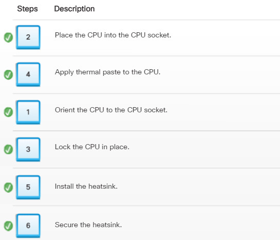
2.1.3.3 – Video Demonstration – Install the RAM
Download transcript of this video:
2.1.3.4 – Check Your Understanding – Install the RAM
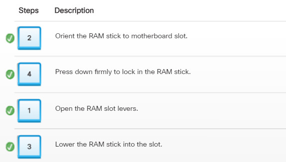
Check Your Understanding – Install the RAM
2.1.3.5 – Video Demonstration – Install the Motherboard
Download transcript of this video:
2.1.3.6 – Check Your Understanding – Install the Motherboard
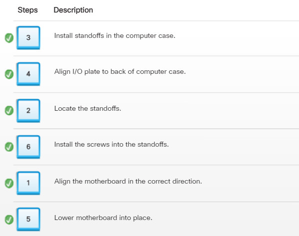
Check Your Understanding – Install the Motherboard
2.1.3.7 – Select the Motherboard
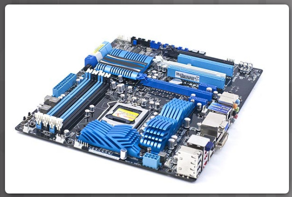
New motherboards often have new features or standards that may be incompatible with older components. When you select a replacement motherboard, make sure that it supports the CPU, RAM, video adapter, and other adapter cards. The socket and chipset on the motherboard must be compatible with the CPU. The motherboard must also accommodate the existing heat sink and fan assembly when reusing the CPU. Pay particular attention to the number and type of expansion slots. Make sure that they match the existing adapter cards and allow for new cards that will be used. The existing power supply must have connections that fit the new motherboard. Finally, the new motherboard must physically fit into the current computer case.
When building a computer, choose a chipset that provides the capabilities that you need. For example, you can purchase a motherboard with a chipset that enables multiple USB ports, eSATA connections, surround sound, and video.
The CPU package must match the CPU socket type. A CPU package contains the CPU, connection points, and materials that surround the CPU and dissipate heat.
Data travels from one part of a computer to another through a collection of wires known as the bus. The bus has two parts. The data portion of the bus, known as the data bus, carries data between the computer components. The address portion, known as the address bus, carries the memory addresses of the locations where data is read or written by the CPU.
The bus size determines how much data can be transmitted at one time. A 32-bit bus transmits 32 bits of data at one time from the processor to RAM, or to other motherboard components, while a 64-bit bus transmits 64 bits of data at one time. The speed at which data travels through the bus is determined by the clock speed, measured in MHz or GHz.
PCI expansion slots connect to a parallel bus, which sends multiple bits over multiple wires simultaneously. PCI expansion slots are being replaced with PCIe expansion slots that connect to a serial bus, which sends one bit at a time at a much faster rate.
When building a computer, choose a motherboard that has slots to meet your current and future needs.
2.1.3.8 – Select the CPU and CPU Cooling
Intel and AMD Sockets

Before you buy a CPU, make sure that it is compatible with the existing motherboard. Manufacturers’ websites are a good resource to investigate the compatibility between CPUs and other devices. The table in Figure 1 lists the various sockets available and their supported processors. The speed of a modern processor is measured in GHz. A maximum speed rating refers to the maximum speed at which a processor can function without errors. Two primary factors can limit the speed of a processor:
The processor chip is a collection of transistors interconnected by wires. Transmitting data through the transistors and wires creates delays.
As the transistors change state from on to off or off to on, a small amount of heat is generated. The amount of heat generated increases as the speed of the processor increases. When the processor becomes too hot, it begins to produce errors.
The front-side bus (FSB) is the path between the CPU and the Northbridge. It is used to connect various components, such as the chipset, expansion cards, and RAM. Data can travel in both directions across the FSB. The frequency of the bus is measured in MHz. The frequency at which a CPU operates is determined by applying a clock multiplier to the FSB speed. For example, a processor running at 3200 MHz might be using a 400 MHz FSB. 3200 MHz divided by 400 MHz is 8, so the CPU is eight times faster than the FSB.
Processors are further classified as 32-bit and 64-bit. The primary difference is the number of instructions that can be handled by the processor at one time. A 64-bit processor processes more instructions per clock cycle than a 32-bit processor. A 64-bit processor can also support more memory. To utilize the 64-bit processor capabilities, ensure that the operating system and applications installed support a 64-bit processor.
The CPU is one of the most expensive and sensitive components in the computer case. The CPU can become very hot; therefore most CPUs require an air-cooled or liquid cooled heat sink, combined with a fan for cooling.
Figure 2 list several factors to consider when choosing a CPU cooling system.
Choosing a CPU Cooling System

2.1.3.9 – Select the RAM
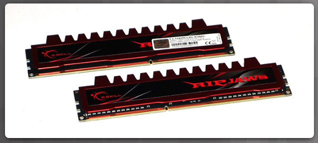
New RAM may be needed when an application locks up or the computer displays frequent error messages. When selecting new RAM, you must ensure that it is compatible with the current motherboard. Memory modules are commonly purchased in matched capacity pairs to support dual channel RAM that can be accessed at the same time. Also, the speed of the new RAM must be supported by the chipset. It may be helpful to take written notes about the original memory module when you shop for the replacement RAM.
Memory may also be categorized as unbuffered or buffered:
- Unbuffered memory – This is regular memory for computers. The computer reads data directly from the memory banks making it faster than buffered memory. However, there is a limit on the amount of RAM that can be installed.
- Buffered memory – This is specialized memory for servers and high-end workstations that use a large amount of RAM. These memory chips have a control chip built into the module. The control chip assists the memory controller in managing large quantities of RAM. Avoid buffered RAM for a gaming computer and the average workstation because the extra controller chip reduces RAM speed.
2.1.3.10 – Lab – Install the Motherboard in a Computer
In this lab, you will install a CPU, a heat sink/fan assembly, and RAM module(s) on the motherboard. You will then install the motherboard in the computer case.
2.1.3.10 – Lab – Install the Motherboard in a Computer Instruction
2.1.4 – Install Internal Drives
2.1.4.1 – Video Demonstration – Install the Drives
Download transcript of this video:
2.1.4.2 – Select Hard Drives
Purchasing a New Hard Disk Drive
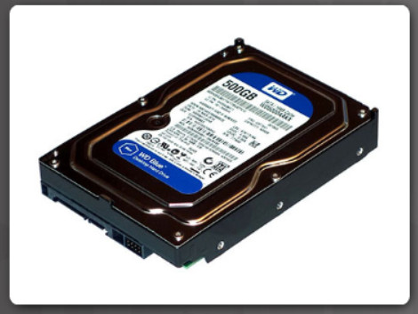
- Internal or external
- HDD, SSD, or SSHD
- Hot-swappable
- Heat generation
- Noise generation
- Power requirements
You may need to replace an internal storage device when it no longer meets your customer’s needs, or it fails. Signs that an internal storage device is failing might be unusual noises, unusual vibrations, error messages, or even corrupt data or applications that do not load.
Factors to consider when purchasing a new hard disk drive are listed in the figure.
Internal drives usually connect to the motherboard with SATA while external drives connect with USB, eSATA, or Thunderbolt. Legacy motherboards may only offer the IDE or EIDE interface. When selecting a HDD, it is important to choose one that is compatible with the interfaces offered by the motherboard.
Most internal HDDs are available in the 3.5 inch (8.9 cm) form factor, however 2.5 inch (6.4 cm) drives are becoming popular. SSDs are generally available in the 2.5 inch (6.4 cm) form factor.
Note: SATA and eSATA cables are similar but they are not interchangeable.
2.1.4.3 – Select Optical Drives
Factors to consider when purchasing an optical drive are listed in Figure 1.
Optical Drive Capabilities
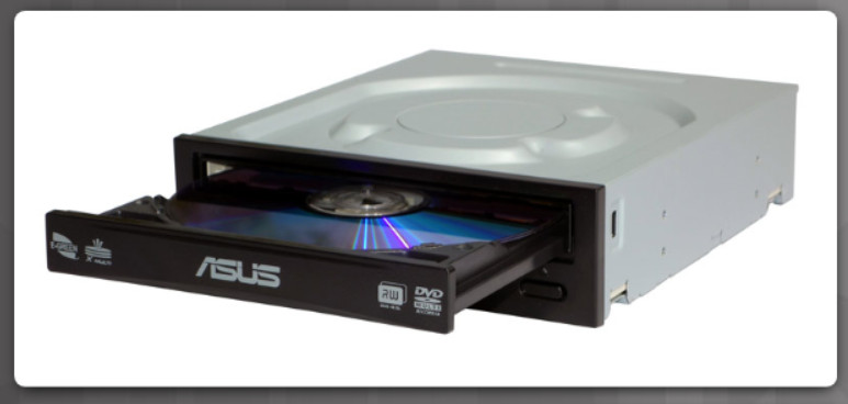
New Optical Drive Factors
- Connector type
- Reading capability
- Writing capability
- Optical media type
The table in Figure 2 summarizes optical drive capabilities.
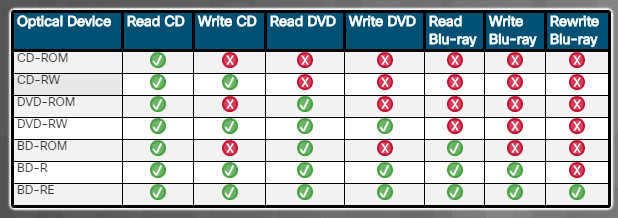
Optical Drive Capabilities
DVDs hold significantly more data than CDs and Blu-ray discs (BD) store significantly more data than DVDs. DVDs and BDs can also have dual layers for recording data, essentially doubling the amount of data that can be recorded on the media.
2.1.4.4 – Install the Hard Drive
Types of Drive Bays

A computer case holds drives in drive bays. The table in Figure 1 describes the three most common types of drive bays.
To install an HDD, find an empty hard drive bay in the case that will accommodate the width of the drive. Smaller drives can often be installed in wider drive bays using special trays or adapters.
When installing multiple drives in a case, it is recommended to maintain some space between the drives to help airflow and enhance cooling. Also, mount the drive with the metal side face up. This metal face helps to dissipate heat from the hard drive.
Insert HDD into the Bay
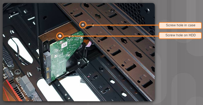
Secure the HDD
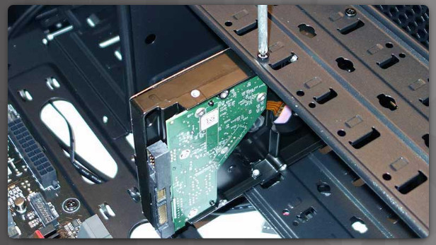
Installation Tip: Slightly hand-tighten all the screws before tightening any of them with a screw driver. This will make it easier to tighten the last two screws.
2.1.4.5 – Install the Optical Drive
Optical drives are installed in 5.25 inch (13.34 cm.) drive bays that are accessed from the front of the case. The bays allow access to the media without opening the case. In new installations, the bays are covered with a plastic insert that keeps dust from entering the case. Remove the plastic cover prior to mounting the drive.
To install an optical drive, follow these steps:
Step 1. From the front of the case, choose the drive bay that you want to hold the drive. Remove the faceplate from that bay if necessary.
Step 2: Position the optical drive so that it aligns with the 5.25 inch (13.34 cm.) drive bay opening at the front of the case, as shown in the figure.
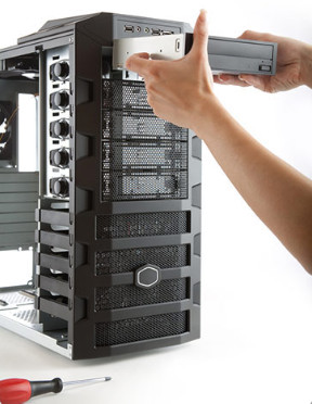
Optical Drive Installation
Step 3. Insert the optical drive into the drive bay so that the optical drive screw holes align with the screw holes in the case.
Step 4. Secure the optical drive to the case using the proper screws.
Installation Tip: Slightly hand-tighten all the screws before tightening any of them with a screw driver. This will make it easier to tighten the last two screws.
2.1.4.6 – Check Your Understanding – Installing Drives
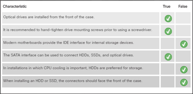
Check-Your-Understanding-Installing-Drives.jpg
2.1.4.7 – Lab – Install the Drives
2.1.4.7 Lab – Install the Drives Instruction Answers
2.1.5 – Install the Adapter Cards
2.1.5.1 – Video Demonstration – Install the Adapter Cards
Download transcript of this video:
2.1.5.2 – Select Adapter Cards
Many of the functions of the hardware of a computer are found onboard the motherboard, such as audio, USB, or network connection. Adapter cards, also called expansion cards or add-on cards, are designed for a specific task and add extra functionality to a computer. They can also be installed when an onboard function has failed. There are a variety of adapter cards available that are used to expand and customize the capability of a computer.
The following list provides an overview of expansion cards that may be upgraded:
Graphics card – The type of graphics card installed affects the overall performance of a computer. For example, a graphics card that needs to support intensive graphics could be RAM intensive, CPU intensive, or both. The computer must have the slots, RAM, and CPU to support the full functionality of an upgraded graphics card. Choose the graphics card based on current and future needs. For example, to play 3D games, the graphics card must meet or exceed the minimum requirements. Some GPUs are integrated into the CPU. When the GPU is integrated into the CPU, there is no need to purchase a graphics card unless advanced video features, such as 3D graphics, or very high resolution are required.
Sound card – The type of sound card installed determines the sound quality of your computer. A computer system must have quality speakers and a subwoofer to support the full functionality of an upgraded sound card. Choose the correct sound card based on your customer’s current and future needs. For example, if a customer wants to hear a specific type of surround sound, the sound card must have the correct hardware decoder to reproduce it. In addition, the customer can get improved sound accuracy with a sound card that has a higher sample rate.
Storage controller – Storage controllers can be integrated or added as an expansion card. They allow for the expansion of internal and external drives for a computer system. Storage controllers, such as RAID controllers, can also provide fault tolerance or increased speed. The amount of data and the level of data protection needed for the customer influences the type of storage controller required. Choose the correct storage controller based on your customer’s current and future needs. For example, if a customer wants to implement RAID 5, a RAID storage controller with at least three drives is needed.
I/O card – Installing an I/O card in a computer is a fast and easy way to add I/O ports. USB are some of the most common ports to install on a computer. Choose the correct I/O card based on your customer’s current and future needs. For example, if a customer wants to add an internal card reader, and the motherboard has no internal USB connection, a USB I/O card with an internal USB connection is needed.
NIC – Customers often upgrade a network interface card (NIC) to get wireless connectivity or to increase bandwidth.
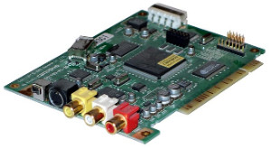
Capture card – A capture card imports video into a computer and records it on a hard drive. The addition of a capture card with a television tuner allows you to view and record television programming. The computer system must have enough CPU power, adequate RAM, and a high-speed storage system to support the capture, recording, and editing demands of the customer. Choose the correct capture card based on your customer’s current and future needs. For example, if a customer wants to record one program while watching another, either multiple capture cards or a capture card with multiple TV tuners must be installed.
Adapter cards are inserted into two types of expansion slots on a motherboard:
- Peripheral Component Interconnect (PCI) – PCI is commonly available to support older expansion cards.
- PCI Express (PCIe) – PCIe has four types of slots; x1, x4, x8, and x16. These PCIe slots vary in length from shortest (X1) to longest (x16) respectively.
The figure displays the different types of expansion slots.
PCI
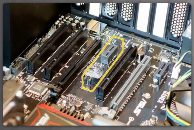
PCle x 1
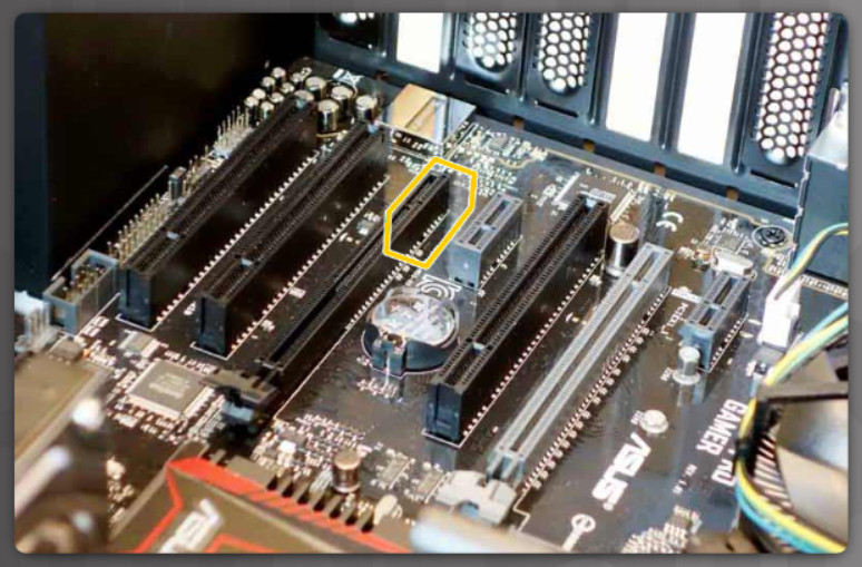
PCle x 16
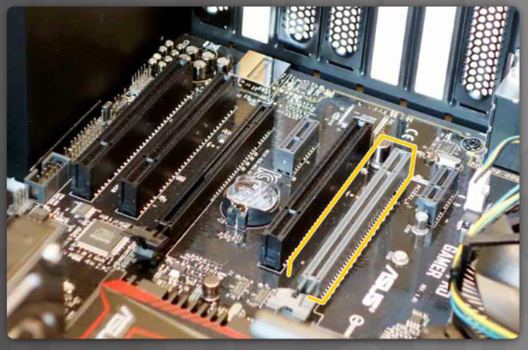
Note: If the motherboard does not have a compatible expansion slot, an external device may be an option.
2.1.5.3 – Other Factors for Adapter Card Selection
- What are the user’s current and future needs?
- Is there an open and compatible expansion slot available?
- What are the possible configuration options?
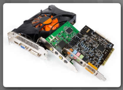
Factors to consider when purchasing a new graphic card
|
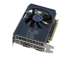 Graphics card |
Factors to consider when purchasing a new sound card
|
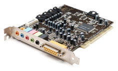 Sound card |
Factors to consider when purchasing a new storage controller card
|
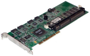 Storage controller card |
Factors to consider when purchasing a new I/O card
|
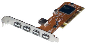 I/O card |
Factors to consider when purchasing a new NIC
|
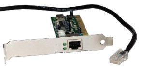 NIC |
Factors to consider when purchasing a new capture card
|
 Capture card |
2.1.5.4 – Install the Adapter Cards
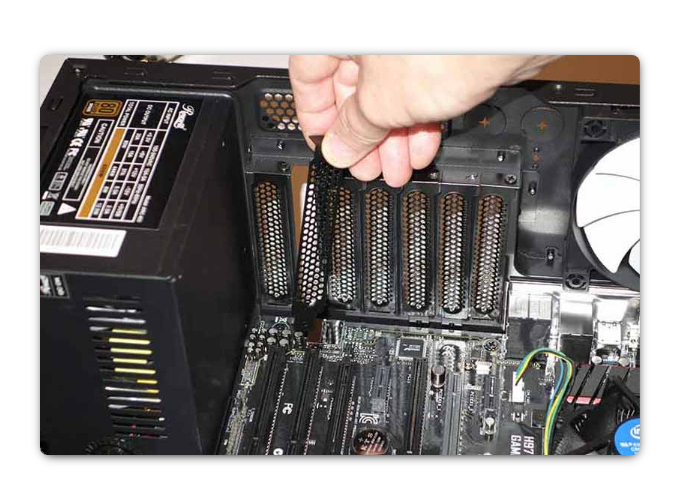
Expansion cards are installed into an empty but appropriate slot on a computer motherboard.
For example, a wireless NIC enables a computer to connect to a wireless (Wi-Fi) network. Wireless NICs can be integrated into the motherboard, connected using a USB connector, or installed using a PCI or PCIe expansion slots on the motherboard.
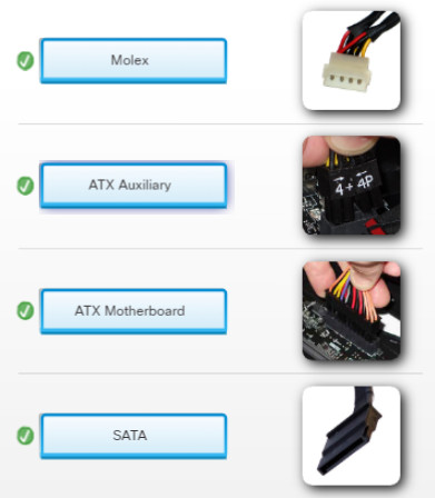
Many video adapter cards require separate power from the power supply using a 6-pin or 8-pin power connector. Some cards may need two of these connectors. If possible, provide some space between the video adapter and other expansion cards. Video adapters create excessive heat, which is often moved away from the card with a fan.
Installation Tip: Research the length of the video card (and other adapter cards) before purchase. Longer cards may not be compatible with certain motherboards. Chips and other electronics may stand in the way of the adapter card when trying to seat them in the expansion slot. Some cases might also limit the size of adapter cards that can be installed. Some adapter cards may come with mounting brackets of different heights to accommodate these cases.
Installation Tip: Some cases have small slots at the bottom of the hole where the cover was removed. Slide the bottom of the mounting bracket into this slot before seating the card.
2.1.5.5 – Check Your Understanding – Installing Adapter Cards
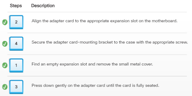
Check Your Understanding – Installing Adapter Cards
2.1.5.6 – Lab – Install Adapter Card
In this lab, you will install a NIC, a wireless NIC, and a video adapter card.
2.1.5.6 – Lab – Install Adapter Card Instruction Answers
2.1.6 – Select Additional Storage
2.1.6.1 – Select a Media Reader
Many digital devices such as cameras, smart phones, and tablets use media cards to store information, music, pictures, videos, data, and more.
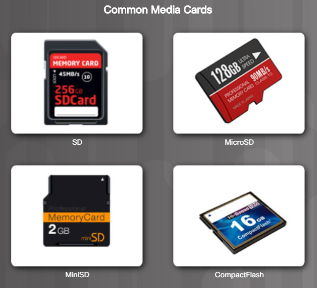
Several media card formats have been developed over the years including:
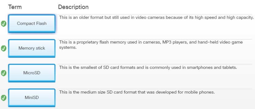
- Secure digital (SD) – SD cards were designed for use in portable devices such as cameras, MP3 players, and laptops. SD cards can hold as much as 2 TB of data.
- MicroSD – This is a much smaller version of SD, commonly used in smartphones and tablets.
- MiniSD – A version of SD between the size of an SD card and a microSD card. The format was developed for mobile phones.
- CompactFlash – CompactFlash is an older format, but still in wide use because of its high speed and high capacity (up to 128 GB is common). CompactFlash is often used as storage for video cameras.
- Memory Stick – Created by Sony Corporation, Memory Stick is a proprietary flash memory used in cameras, MP3 players, hand-held video game systems, mobile phones, cameras, and other portable electronics.
- xD – Also known as Picture Card, it was used in some digital cameras.
Figure 1 displays some of these media cards.
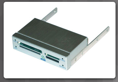
It is useful to have an internal or external device that can be used to read or write to media cards. When purchasing or replacing a media reader, ensure that it supports the types of media cards that will be used.
Figure 2 displays an external media card reader and lists factors to consider when purchasing a media reader.
Choose the correct media reader based on your customer’s current and future needs. For example, if a customer needs to use multiple types of media cards, a multiple format media reader is needed.
New Media Reader Factors
- Media cards supported
- Internal or external
- Size
- Connector type
2.1.6.2 – Select External Storage
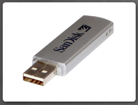
External storage offers portability and convenience when working with multiple computers. External USB flash drives, sometimes called thumb drives, are commonly used as removable external storage. External storage devices connect to an external port using USB, eSATA, or Thunderbolt ports.
The figure displays an external flash drive and lists factors to consider when purchasing an external storage solution.
Choose the correct type of external storage for your customer’s needs. For example, if your customer needs to transfer a small amount of data, such as a single presentation, an external flash drive is a good choice. If your customer needs to back up or transfer large amounts of data, choose an external hard drive.
Purchasing a New External Storage Solution
New External Storage Factors
- Port type
- Storage capacity
- Speed
- Portability
- Power requirements
2.1.6.3 – Check Your Understanding – Media Cards
2.1.7 – Install the Cables
2.1.7.1 – Video Demonstration – Connect the Internal Power Cables
Download transcript of this video:
2.1.7.1 Video Demonstration - Connect the Internal Power Cables.pdf 116.05 KB 839 downloads
...2.1.7.2 – Check Your Understanding – Identify the Power Connectors
2.1.7.3 – Video Demonstration – Connect the Internal Data Cables
Download transcript of this video:
2.1.7.3 Video Demonstration - Connect the Internal Data Cables.pdf 110.83 KB 764 downloads
...2.1.7.4 – Lab – Install Internal Cables
In this lab, install the internal power and data cables in the computer.
2.1.7.4 – Lab – Install Internal Cables Instruction Answers
2.1.7.5 – Video Demonstration – Install the Front Panel Cables
Download transcript of this video:
2.1.7.5 Video Demonstration - Install the Front Panel Cables.pdf 115.69 KB 856 downloads
...2.1.7.6 – Install the Front Panel Cables
Front Panel Connectors
System Panel Connectors
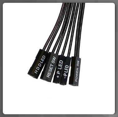
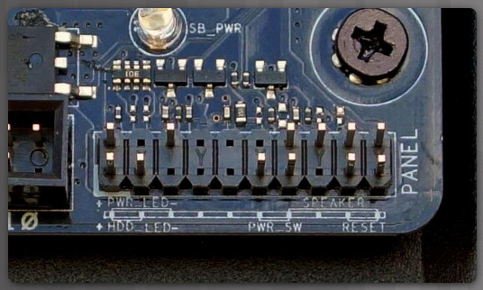
A computer case typically has a power button and visible activity lights on the front of the case. The case will include front panel cables that must be connected to a common system panel connector on a motherboard as shown in Figure 1. Writing on the motherboard near the system panel connector shows where each cable is connected.
System panel connectors include:
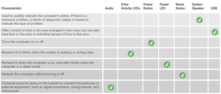
- Power Button – The power button turns the computer on or off. If the power button fails to turn off the computer, hold down the power button for several (i.e., 5 or more) seconds.
- Reset Button – The reset button (if available) restarts the computer without turning it off.
- Power LED – The power LED remains lit when the computer is on, and often blinks when the computer is in sleep mode.
- Drive Activity LEDs – The drive activity LED remains lit or blinks when the system is reading or writing to hard drives.
- System Speaker – The motherboard uses a case speaker (if available) to indicate the computer’s status. For example, one beep indicates that the computer started without problems. If there is a hardware problem, a series of diagnostic beeps is issued to indicate the type of problem. It is important to note that the system speaker is not the same as the speakers the computer uses to play music and other audio. The system speaker cable typically uses four pins on the system panel connector.
- Audio – Some cases have audio ports and jacks on the outside to connect microphones, external audio equipment such as signal processors, mixing boards, and instruments. Special audio panels can also be purchased and connected directly to the motherboard. These panels can install into one or more external drive bays, or be standalone panels.
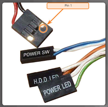
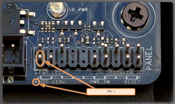
System panel connectors are not keyed. However, each front panel cable usually has a small arrow indicating pin 1, and each pair of LED pins on the motherboard system panel connector has pin 1 marked with a plus sign (+), as shown in Figure 2.
Pin 1 Arrow Indicator
System Panel Connectors Pin 1 Indicator
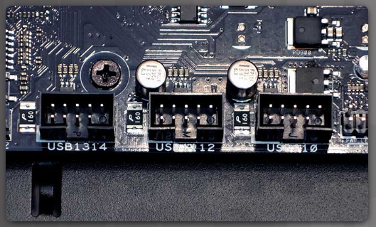
New cases and motherboards have USB 3.0 or may even have USB 3.1 capabilities. The USB 3.0 and 3.1 motherboard connector is similar in design to a USB connector, but has additional pins. USB connector cables are often 9 or 10 pins arranged in two rows. These cables connect to USB motherboard connectors as shown in Figure 3. This arrangement allows for two USB connections, so USB connectors are often in pairs. Sometimes the two connectors are together in one piece, as shown in the figure, and can be connected to the entire USB motherboard connector. USB connectors can also have four or five pins or individual groups of four or five pins. Most USB devices only require the connection of four pins. The fifth pin is used to ground the shielding of some USB cables.
USB Motherboard Connectors
Internal USB Connectors
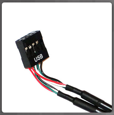
CAUTION: Make sure that the motherboard connector is marked USB. FireWire connectors are very similar. Connecting a USB cable to a FireWire connector will cause damage.
The table in Figure 4 provides connecting notes on various front panel connections.
Front Panel Cable Connection Specifics
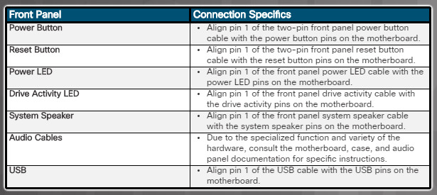
Generally, if a button or LED does not function, the connector is incorrectly oriented. To correct this, shut down the computer and unplug it, open the case, and turn the connector around for the button or LED that does not function. To avoid wiring incorrectly, some manufacturers include a keyed pin extender that combines multiple front-panel cables (i.e., power and reset LEDs) connectors into one connector.
Installation Tip: The panel connector and case cable ends are very small. Take pictures of them to locate pin 1. Because space in the case can be limited at the end of assembly, a part retriever can be used to plug the cables into the connectors.
2.1.7.7 – Checking Your Understanding – Identify the Front Panel Cables
2.1.7.8 – Lab – Install the Front Panel Cables
In this lab, you will install the front panel cables in the computer.
2.1.7.8 – Lab – Install the Front Panel Cables Instruction
2.1.7.9 – Video Demonstration – Complete the Computer Assembly
Download transcript of this video:
2.1.7.9 Video Demonstration - Complete the Computer Assembly.pdf 115.59 KB 815 downloads
...2.1.7.10 – Check Your Understanding – Identify the External Connectors
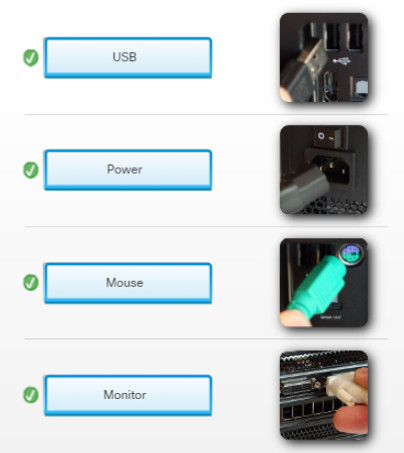
2.1.7.11 – Lab – Complete the Computer Assembly
In this lab, you will install the side panels and the external cables on the computer.
2.1.7.11 – Lab – Complete the Computer Assembly Instruction
2.2 – Summary
In this chapter you learned that assembling computers is often a large part of a technician’s job and that as a technician, you must work in a logical, methodical manner when working with computer components. For example, the choice of motherboard and external components influences the selection of the case and power supply and the motherboard form factor must be matched with the correct type of computer case and power supply.
You learned that PC power supplies convert AC input to DC output voltages. Power supplies typically provide voltages of 3.3V, 5V, and 12V to power the various internal components of the computer and that the power supply must have the proper connectors for the motherboard and the various types of devices to be powered.
After learning about power supplies, you installed a power supply as well as other internal components including a CPU and RAM. You learned that when you select a motherboard it must support the CPU, RAM, video adapter, and other adapter cards and that the socket and chipset on the motherboard must be compatible with the CPU. The motherboard sockets may be designed to support Intel CPUs, which support an LGA architecture, or AMD CPUs which support a PGA architecture.
In addition to learning about CPU architectures, you also learned that when selecting new RAM, it must be compatible with the motherboard and that the speed of the RAM must be supported by the chipset. You then performed labs where you installed a CPU, a heat sink/fan assembly, and RAM modules on the motherboard. You also installed the motherboard assembly into the computer case.
Next, you learned about the various types of storage drives, such as internal drives, external drives, hard-disk drives, solid-state drives, and optical drives and the factors to consider when selecting the appropriate drive. You then installed drives in the computer case.
Finally, you learned about adapter cards, which are also called expansion cards, or add-on cards. There are many types of adapter cards and each is designed for a specific task and to add extra functionality to a computer. The chapter covered graphics cards, sound cards, storage controllers, I/O cards, and NICs. These adapter cards are inserted into two types of expansion slots on a motherboard: PCI and PCIe. At the end of the chapter, there were labs where you installed an adapter card, connected the appropriate internal power cables, front panel connectors, and performed final computer assembly.
