
15.2.2 Packet Tracer - Configure NAT for IPv4 (Answers)
Topology
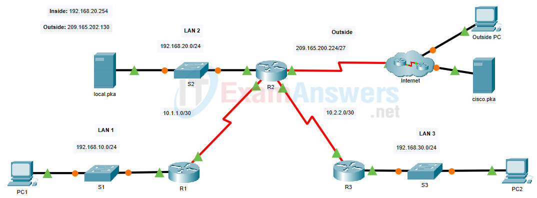
15.2.2 Packet Tracer - Configure NAT for IPv4
Addressing Table
| Device | Interface | IP Address |
|---|---|---|
| R1 | S0/0/0 | 10.1.1.1/30 |
| F0/0 | 192.168.10.1/24 | |
| R2 | S0/0/0 | 10.1.1.2/30 |
| S0/0/1 | 10.2.2.1/30 | |
| S0/1/0 | 209.165.200.225/27 | |
| F0/0 | 192.168.20.1/24 | |
| R3 | S0/0/1 | 10.2.2.2/30 |
| F0/0 | 192.168.30.1/24 | |
| PC1 | NIC | 192.168.10.10/24 |
| PC2 | NIC | 192.168.30.10/24 |
| local.pka | NIC | 192.168.20.254/24 |
| Outside PC | NIC | 209.165.201.14/28 |
| cisco.pka | NIC | 209.165.201.30/28 |
Objectives
- Configure Dynamic NAT with PAT
- Configure Static NAT
Background / Scenario
In this lab, you will configure a router with dynamic NAT with PAT. This will translate addresses from the three internal LANs to a single outside address. In addition, you will configure static NAT to translate an internal server address to an outside address.
Instructions
In this activity you will only configure router R2.
- Use a named ACL to permit the addresses from LAN1, LAN2, and LAN3 to be translated. Specify the LANs in this order. Use the name R2NAT. The name you use must match this name exactly.
- Create a NAT pool named R2POOL. The pool should use the first address from the 165.202.128/30 address space. The pool name you use must match this name exactly. All translated addresses must use this address as their outside address.
- Configure NAT with the ACL and NAT pool that you have created.
- Configure static NAT to map the local.pka server inside address to the second address from the 165.202.128/30 address space.
- Configure the interfaces that will participate in NAT.
Device Configs - Final
Router R2
! ==============================================================
!--- 15.2.2 Packet Tracer - Configure NAT for IPv4
!--- ANSWER SCRIPT FOR ROUTER R2
!--- Usage: copy this whole file and paste it into the R2 terminal (start at the R2> prompt). Every line beginning with "!" is a comment; IOS ignores it, so pasting a comment by accident is harmless.
!--- Scope: only R2 is configured in this activity - R1, R3 and all
!--- switches/PCs are already set up per the addressing table.
! ==============================================================

enable
configure terminal

! --------------------------------------------------------------
!--- Part 1: Define which traffic is allowed to be translated.
!--- Named ACL R2NAT permits LAN1, LAN2 and LAN3 in that exact order,
!--- as required.
! --------------------------------------------------------------

ip access-list standard R2NAT
 permit 192.168.10.0 0.0.0.255
 permit 192.168.20.0 0.0.0.255
 permit 192.168.30.0 0.0.0.255
 exit

! --------------------------------------------------------------
!--- Part 2: Create the dynamic NAT pool for PAT overload.
!--- 209.165.202.128/30 has two usable host addresses: .129 (first)
!--- and .130 (second). The pool uses only the first one, .129, since
!--- every dynamically-translated host will share it via overload.
! --------------------------------------------------------------

ip nat pool R2POOL 209.165.202.129 209.165.202.129 netmask 255.255.255.252

! --------------------------------------------------------------
!--- Part 3: Tie the ACL and the pool together as dynamic NAT with PAT.
!--- "overload" is what makes this PAT (many inside hosts sharing one
!--- outside address) rather than plain one-to-one dynamic NAT.
! --------------------------------------------------------------

ip nat inside source list R2NAT pool R2POOL overload

! --------------------------------------------------------------
!--- Part 4: Static NAT for the local.pka server - always reachable
!--- from outside at the same address, using the pool's second usable
!--- address, .130.
! --------------------------------------------------------------

ip nat inside source static 192.168.20.254 209.165.202.130

! --------------------------------------------------------------
!--- Part 5: Mark each interface as NAT inside or outside. Every LAN
!--- reaches the Internet through R2, so both branch serial links
!--- (which carry LAN1's and LAN3's traffic to R2) count as inside,
!--- along with R2's own local LAN2 interface. Only the link facing the
!--- Internet is outside.
! --------------------------------------------------------------

interface fastethernet 0/0
 ip nat inside
 exit
interface serial 0/0/0
 ip nat inside
 exit
interface serial 0/0/1
 ip nat inside
 exit
interface serial 0/1/0
 ip nat outside
 exit

end

! --------------------------------------------------------------
!--- Save the configuration to NVRAM. (Press Enter when prompted for the destination filename.)
! --------------------------------------------------------------
copy running-config startup-config


! ==============================================================
!--- Verification:
!---   show ip nat translations   -> static entry for 192.168.20.254 <-> 209.165.202.130 always present
!---   show ip nat statistics     -> pool R2POOL, 1 address, overload; ACL R2NAT hit count
!---   show access-lists R2NAT    -> permits in the order 10.0/20.0/30.0
!---   ping 209.165.201.30 / 209.165.201.14 (from PC1, local.pka, PC2)  -> Outside PC / cisco.pka, translated via overload
!--- Note: the lab's own Addressing Table lists R2's LAN2 interface as
!--- "F0/0/0" (three segments), but the Topology diagram and this
!--- script both use "F0/0" (two segments) - matching what a router
!--- with a single onboard FastEthernet port actually exposes. Likely a
!--- stray extra "/0" in the published table, not a real third
!--- interface segment.
! ==============================================================

