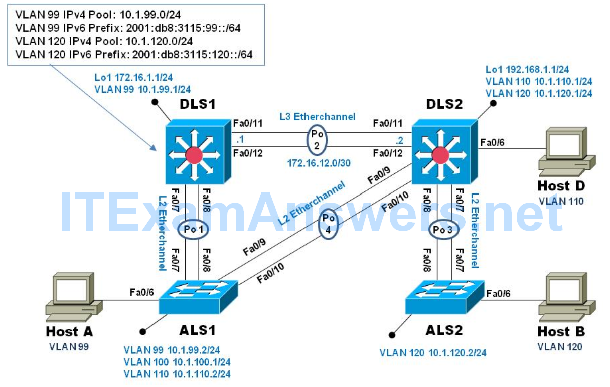
Topology

Objectives
- Configure DHCP for IPv4
- Configure Stateless DHCP for IPv6
- Configure Stateful DHCP for IPv6
Background
To practice the various configuration and options associated with DHCP for IPv4 and IPv6, you will configure a DHCP server on switch DLS1. Hosts A and B will receive IP addresses from DLS1 and validate continued connectivity.
Note: This lab uses Cisco Catalyst 3560 and 2960 switches running Cisco IOS 15.0(2)SE6 IP Services and LAN Base images, respectively. The 3560 and 2960 switches are configured with the SDM templates “dualipv4-and-ipv6 routing” and “lanbase-routing”, respectively. Depending on the switch model and Cisco IOS Software version, the commands available and output produced might vary from what is shown in this lab. Catalyst 3650 switches (running any Cisco IOS XE release) and Catalyst 2960-Plus switches (running any comparable Cisco IOS image) can be used in place of the Catalyst 3560 switches and the Catalyst 2960 switches.
Required Resources
- 2 Cisco 2960 with the Cisco IOS Release 15.0(2)SE6 C2960-LANBASEK9-M or comparable
- 2 Cisco 3560v2 with the Cisco IOS Release 15.0(2)SE6 C3560-IPSERVICESK9-M or comparable
- Computer with terminal emulation software
- Ethernet and console cables
- 3 Windows 7 PCs with appropriate software
Step 1: Verify SDM template (dual-ipv4-and-ipv6 routing / lanbase-routing)
This lab starts with the switches being configured from the previous lab (5-1, Inter-VLAN Routing). To support IPv6, the correct SDM template must be in use on your switches (the 3560 will use dual-ipv4-and-ipv6 routing while the 2960 will use lanbase-routing). Verify this is the case on all four switches. If you must change the SDM template, do so (use the configuration command sdm prefer dual-ipv4-and-ipv6 routing on the 3560s and sdm prefer lanbase-routing on the 2960s) and then save the switch configuration and reload the switch to have the new SDM template take effect.
Step 2: Configure IPv4 DHCP server on DLS1 for VLAN 99 and 120
Configure a DHCP server for IPv4 on DLS1 using the following parameters:
For VLAN 99:
- Exclude addresses 10.1.99.1 through 10.1.99.2 and 10.1.99.100 through 10.1.99.104
- Set the default router to 10.1.99.1
- Set the DNS server to 10.1.99.100
For VLAN 120:
- Exclude addresses 10.1.120.1 through 10.1.120.2 and 10.1.120.100 through 10.1.120.104
- Set the default router to 10.1.120.1
- Set the DNS server to 10.1.99.100
Configure Interface F0/6 as an access port in VLAN 99 and issue the no shut command
Example of VLAN 99 pool configuration:
DLS1#conf t
Enter configuration commands, one per line. End with CNTL/Z.
DLS1(config)#ip dhcp excluded-address 10.1.99.1 10.1.99.2
DLS1(config)#ip dhcp excluded-address 10.1.99.100 10.1.99.104
DLS1(config)#ip dhcp pool VLAN99_DHCP
DLS1(dhcp-config)#network 10.1.99.0 255.255.255.0
DLS1(dhcp-config)#default-router 10.1.99.1
DLS1(dhcp-config)#dns-server 10.1.99.100
DLS1(dhcp-config)#exit
DLS1(config)#end
DLS1#
Step 3: Configure IPv6 support on all switches
Configure IPv6 support addresses on all switches using the following addresses:
• Enable IPv6 unicast-routing on DLS1 and DLS2
• Configure IPv6 addressing as shown in the table:
| Device | Interface | Link-Local Address | Global Unicast Address |
|---|---|---|---|
| DLS1 | VLAN99 | Fe80::d1 | 2001:db8:3115:99::d1/64 |
| DLS2 | VLAN110 | Fe80::d2 | 2001:db8:3115:110::d2/64 |
| DLS2 | VLAN120 | Fe80::d2 | 2001:db8:3115:120::d2/64 |
| ALS1 | VLAN99 | Fe80::a1 | 2001:db8:3115:99::a1/64 |
| ALS2 | VLAN120 | Fe80::a2 | 2001:db8:3115:120::a2/64 |
| DLS1 | Po2 | Fe80::d1 | 2001:db8:3115:12::d1/64 |
| DLS2 | Po2 | Fe80::d2 | 2001:db8:3115:12::d2/64 |
Step 4: Configure IPv6 Routing at DLS1 and DLS2
At DLS1 and DLS2, create an IPv6 default route that points to the other switch. Example from DLS1:
DLS1(config)#ipv6 route ::/0 2001:db8:3115:12::d2
Step 5: Configure a STATELESS DHCP server for IPv6 on DLS1 using the following parameters:
• Build a pool named MANAGEMENT_IPV6_DHCP
• Set the DNS server to 2001:db8:3115:99::100
• Associate the IPv6 pool with interface vlan 99 on DLS1
• Set the Other configuration flag on interface vlan 99 on DLS1
DLS1#conf t
Enter configuration commands, one per line. End with CNTL/Z.
DLS1(config)#ipv6 dhcp pool MANAGEMENT_IPV6_DHCP
DLS1(config-dhcpv6)#dns-server 2001:db8:3115:99::100
DLS1(config-dhcpv6)#exit
DLS1(config)#interface vlan 99
DLS1(config-if)#ipv6 dhcp server MANAGEMENT_IPV6_DHCP
DLS1(config-if)#ipv6 nd other-config-flag
DLS1(config-if)#exit
DLS1(config)#end
DLS1#
Step 6: Configure DHCP Relay on DLS2 for the VLAN 120 network
Redirect IPv4 and IPv6 DHCP requests to DLS1 at 10.1.99.1 and 2001:db8:3115:99::d1 respectively
DLS2(config)# int vlan 120
DLS2(config-if)# ipv6 dhcp relay destination 2001:db8:3115:99::d1 po2
DLS2(config-if)# ip helper-address 10.1.99.1
DLS2(config-if)# exit
Step 7: Configure switches for remote access
On each switch, create an enable secret password and configure the vty lines to allow remote access from other network devices.
DLS1 example:
DLS1(config)# enable secret class
DLS1(config)# line vty 0 4
DLS1(config-line)# password cisco
DLS1(config-line)# login
Note: The passwords configured here are required for NETLAB compatibility only and are NOT recommended for use in a live environment
Step 8: Configure hosts for both IPv4 and IPv6 addresses
Hosts should be attached to interface F0/6 on DLS2, ALS1 and ALS2.
• On ALS1, change interface F0/6 from an access port in VLAN 100 to an access port in VLAN 99.
• On ALS2, configure interface F0/6 as an access port in VLAN 120
• On DLS2, verify F0/6 is configured as an access port in VLAN 110.
First, verify that Host D (connected to DLS2 F0/6) receives an IP address from the VLAN 110 pool.
For the rest of this step, you will work with Host A connected to ALS1.
Once the interface on ALS1 is associated with proper VLAN, use the commands appropriate to the PC operating system to obtain IPv4 and IPv6 addressing.
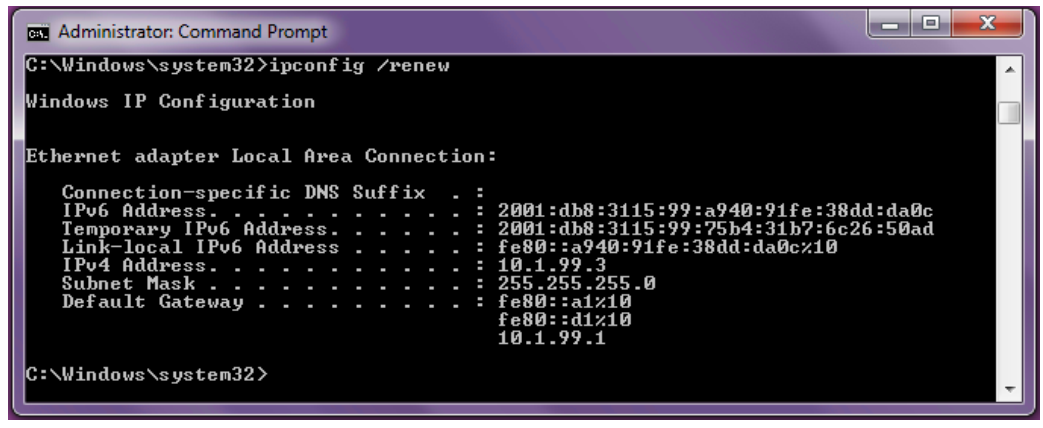
For a computer with Windows 7 installed (must be machine administrator): At the command prompt, issue the command ipconfig /renew to get an IPv4 address and ipconfig /renew6 to get an IPv6 address.

In the ipconfig output above, notice that there are two IPv6 addresses. The first address listed, 2001:db8:3115:99:a940:91fe:38dd:da0c is a permanent address while the second address listed, 2001:db8:3115:99:75b4:31b7:6c26:50ad, is a temporary address.
Also notice that the interface portion of the permanent address is the same as the interface portion of the linklocal address.
The temporary address is generated automatically because privacy extensions are enabled.
The permanent address will be used in DNS registration and when this host is providing a service, while the temporary address will be used when this host is serving in the client role and requesting services from another host, with the idea that this helps provide some privacy to the host.
The temporary address is valid for one day then a new temporary address is generated and then the old temporary address goes into a “deprecated” mode for seven days. The “active” temporary address may also be referred to as “preferred”.
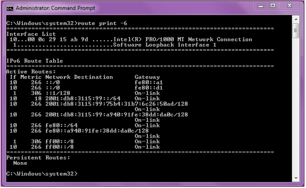
The second thing to note is from the output of the route print -6 command:

The default route, expressed as ::/0, points to the link-local address of the default gateway; there is also a route to the local IPv6 network 2001:db8:3115:99::/64 noted as “on link”.
Step 9: Test connectivity using IPv4 and IPv6 addresses
From Host A, attempt to ping and telnet to DLS2 using both IPv4 (10.1.110.1) and IPv6 addresses (2001:db8:3115:110::d2). All attempts should succeed.
Step 10: Configure Stateful DHCP for IPv6
In this step, you will configure stateful DHCP for VLAN 120. In this scenario, DLS1 will be providing DHCP services for VLAN 120 even though it does not have an interface on VLAN 120. The DHCP Helper configuration from step 6 will allow DHCP traffic from HOST B to reach the DHCP server. However, some additional configuration is necessary on DLS2 to ensure everything works as expected.
In most cases when an external DHCP server is used, the device sourcing router advertisement (DLS2 in this instance) simply has to have the “M” flag enabled on the interface receiving the DHCP Solicit messages.
The M flag being received in the RA will cause the host to ask for a DHCP address. However, it will also
configure a SLAAC address using the prefix information in the RA. This is due to the fact that the autoconfig flag is on by default. The “A” flag tells the host to use the RA to build an address for the interface. We will illustrate this with a very different DHCP prefix and a couple of packet captures and debug outputs in a few moments.
• Configure DLS1 with an IPv6 DHCP pool named VLAN120-IPV6-POOL
• Set the address prefix to 3333:120::/64
• Set the DNS server to 2001:db8:3115:99::100
• Set the domain name to switch.ccnp
• Apply this DHCP configuration to interface Port-Channel 2
DLS1(config)# ipv6 dhcp pool VLAN120-IPV6-POOL
DLS1(config-dhcpv6)# address prefix 3333:120::/64
DLS1(config-dhcpv6)# dns-server 2001:db8:3115:99::100
DLS1(config-dhcpv6)# domain-name switch.ccnp
DLS1(config-dhcpv6)# exit
DLS1(config)# interface port-channel 2
DLS1(config-if)# ipv6 dhcp server VLAN120-IPV6-POOL
• Set the managed configuration flag on interface vlan 120 on DLS2
DLS2(config)# int vlan 120
DLS2(config-if)# ipv6 nd managed-config-flag
DLS2(config-if)# exit
Step 11: Configure the hosts for IPv6 addresses
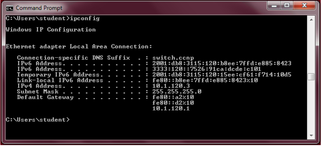
Use the previously provided instructions on Host B to obtain an IPv6 address. If you do NOT receive an address with the 3333:120::/64 prefix, make sure DHCP relay is working. You can use debug ipv6 dhcp relay on DLS2 and debug ipv6 dhcp on DLS1.

Notice the IPv6 addresses. This machine has two addresses with the 2001:db8:3115:120::/64 prefix, and only one from the 3333:120::/64 prefix. What happened?
The results here are a result of the autoconfig flag being set in the router advertisements sent by DLS2. The “A” flag being on tells the host to use the RA to create an address, even if the “M” flag is on. To see the “A” flag, you could use Wireshark on the host or simply debug ipv6 nd on DLS2:
*Mar 1 05:11:45.135: ICMPv6-ND: Request to send RA for FE80::D2
*Mar 1 05:11:45.135: ICMPv6-ND: Setup RA from FE80::D2 to FF02::1 on Vlan120
*Mar 1 05:11:45.135: ICMPv6-ND: Setup RA common:Managed address configuration
*Mar 1 05:11:45.135: ICMPv6-ND:  MTU = 1500
*Mar 1 05:11:45.135: ICMPv6-ND:   prefix = 2001:DB8:3115:120::/64 onlink autoconfig
*Mar 1 05:11:45.135: ICMPv6-ND:    2592000/604800 (valid/preferred)
We used different numbers on the DLS2 VLAN120 interface and the DHCP scope to illustrate the impact of the autoconfig flag.
To make DLS2 remove the autoconfig flag from the RA, add the ipv6 nd prefix xx::/yy no-autoconfig interface configuration command (xx::/yy is the prefix assigned to int VLAN 120).
Please note that as of this writing, the no-autoconfig parameter is hidden, so it will not appear in help or tabcompletion.
DLS2(config)#int vlan 120
DLS2(config-if)#ipv6 nd prefix 2001:db8:3115:120::/64 no-autoconfig
DLS2(config-if)#end
*Mar 1 06:19:21.891: ICMPv6-ND: Setup RA common:Managed address configuration
*Mar 1 06:19:21.891: ICMPv6-ND: MTU = 1500
*Mar 1 06:19:21.891: ICMPv6-ND:     prefix = 2001:DB8:3115:120::/64 onlink
*Mar 1 06:19:21.891: ICMPv6-ND:             2592000/604800 (valid/preferred)
Note: Due to the way the values are stored, your Windows 7 host may not release the originally configured addresses in the 2001::db8:3115:120::/64 network.
Now, reconfigure the DHCP pool at DLS1 to use the correct prefix for VLAN 120 (2001:db8:3115:120::/64), disable and re-enable the adapter on HOST B, and the host should receive a single IPv6 address. Due to the fact that this is the same prefix, and the way Windows generates the random interface ID, this will most likely be the same address.
DLS1(config)# no ipv6 dhcp pool VLAN120-IPV6-POOL
DLS1(config)# ipv6 dhcp pool VLAN120-IPV6-POOL
DLS1(config-dhcpv6)# address prefix 2001:db8:3115:120::/64
DLS1(config-dhcpv6)# dns-server 2001:db8:3115:99::100
DLS1(config-dhcpv6)# domain-name switch.ccnp
DLS1(config-dhcpv6)# interface po2
DLS1(config-if)# ipv6 dhcp server VLAN120-IPV6-POOL
Step 12: Test connectivity
As you did in step 9, test connectivity between the hosts using PING and TELNET.
Step 13: End of Lab
Use the tcl script “reset.tcl” created in Lab 1 to clear and reload all of your switches before the next lab.
Device Configurations:
Below are the final configurations for each switch.
DLS1:
DLS1# show run | exclude !
Building configuration...

Current configuration : 3586 bytes
version 15.0
no service pad
service timestamps debug datetime msec
service timestamps log datetime msec
no service password-encryption
hostname DLS1
boot-start-marker
boot-end-marker
enable secret 5 $1$fGsq$T7aNeecM3pExyGr261H9R/
no aaa new-model
system mtu routing 1500
vtp mode transparent
ip routing
no ip domain-lookup
ip domain-name CCNP.NET
ip dhcp excluded-address 10.1.99.1 10.1.99.2
ip dhcp excluded-address 10.1.99.100 10.1.99.104
ip dhcp excluded-address 10.1.120.1 10.1.120.2
ip dhcp excluded-address 10.1.120.100 10.1.120.104
ip dhcp pool VLAN99_DHCP
network 10.1.99.0 255.255.255.0
default-router 10.1.99.1
dns-server 10.1.99.100
ip dhcp pool VLAN120_DHCP
network 10.1.120.0 255.255.255.0
default-router 10.1.120.1
dns-server 10.1.99.100
ipv6 unicast-routing
ipv6 dhcp pool MANAGEMENT_IPV6_DHCP
dns-server 2001:DB8:3115:99::100
ipv6 dhcp pool VLAN120-IPV6-POOL
address prefix 2001:DB8:3115:120::/64
dns-server 2001:DB8:3115:99::100
domain-name switch.ccnp
spanning-tree mode pvst
spanning-tree extend system-id
vlan internal allocation policy ascending
vlan 99
name MGMT1
interface Loopback1
ip address 172.16.1.1 255.255.255.0
interface Port-channel1
switchport trunk encapsulation dot1q
switchport trunk allowed vlan 1-109,111-4094
switchport mode trunk
interface Port-channel2
no switchport
ip address 172.16.12.1 255.255.255.252
ipv6 address FE80::D1 link-local
ipv6 address 2001:DB8:3115:12::D1/64
ipv6 dhcp server VLAN120-IPV6-POOL
interface FastEthernet0/1
shutdown
interface FastEthernet0/2
shutdown
interface FastEthernet0/3
shutdown
interface FastEthernet0/4
shutdown
interface FastEthernet0/5
shutdown
interface FastEthernet0/6
switchport access vlan 99
switchport mode access
spanning-tree portfast
interface FastEthernet0/7
switchport trunk encapsulation dot1q
switchport trunk allowed vlan 1-109,111-4094
switchport mode trunk
channel-group 1 mode desirable
interface FastEthernet0/8
switchport trunk encapsulation dot1q
switchport trunk allowed vlan 1-109,111-4094
switchport mode trunk
channel-group 1 mode desirable
interface FastEthernet0/9
shutdown
interface FastEthernet0/10
shutdown
interface FastEthernet0/11
no switchport
no ip address
channel-group 2 mode desirable
interface FastEthernet0/12
no switchport
no ip address
channel-group 2 mode desirable
interface FastEthernet0/13
shutdown
interface FastEthernet0/14
shutdown
interface FastEthernet0/15
shutdown
interface FastEthernet0/16
shutdown
interface FastEthernet0/17
shutdown
interface FastEthernet0/18
shutdown
interface FastEthernet0/19
shutdown
interface FastEthernet0/20
shutdown
interface FastEthernet0/21
shutdown
interface FastEthernet0/22
shutdown
interface FastEthernet0/23
shutdown
interface FastEthernet0/24
shutdown
interface GigabitEthernet0/1
shutdown
interface GigabitEthernet0/2
shutdown
interface Vlan1
no ip address
shutdown
interface Vlan99
ip address 10.1.99.1 255.255.255.0
ipv6 address FE80::D1 link-local
ipv6 address 2001:DB8:3115:99::D1/64
ipv6 nd other-config-flag
ipv6 dhcp server MANAGEMENT_IPV6_DHCP
ip http server
ip http secure-server
ip route 0.0.0.0 0.0.0.0 Port-channel2 172.16.12.2
ip route 10.1.100.0 255.255.255.0 Vlan99
ipv6 route ::/0 2001:DB8:3115:12::D2
line con 0
exec-timeout 0 0
logging synchronous
line vty 0 4
password cisco
login
line vty 5 15
login
end
DLS2:
DLS2# show run | exclude !
Building configuration...

Current configuration : 3434 bytes
version 15.0
no service pad
service timestamps debug datetime msec
service timestamps log datetime msec
no service password-encryption
hostname DLS2
boot-start-marker
boot-end-marker
enable secret 5 $1$YDR/$Dop/MzbYbITZkzmeo7jl40
no aaa new-model
system mtu routing 1500
vtp mode transparent
ip routing
no ip domain-lookup
ip domain-name CCNP.NET
ipv6 unicast-routing
spanning-tree mode pvst
spanning-tree extend system-id
vlan internal allocation policy ascending
vlan 110
name INTERNODE
vlan 120
name MGMT2
interface Loopback1
ip address 192.168.1.1 255.255.255.0
interface Port-channel2
no switchport
ip address 172.16.12.2 255.255.255.252
ipv6 address FE80::D2 link-local
ipv6 address 2001:DB8:3115:12::D2/64
interface Port-channel3
switchport trunk encapsulation dot1q
switchport mode trunk
interface Port-channel4
switchport trunk encapsulation dot1q
switchport trunk allowed vlan 110
switchport mode trunk
interface FastEthernet0/1
shutdown
interface FastEthernet0/2
shutdown
interface FastEthernet0/3
shutdown
interface FastEthernet0/4
shutdown
interface FastEthernet0/5
shutdown
interface FastEthernet0/6
switchport access vlan 110
switchport mode access
spanning-tree portfast
interface FastEthernet0/7
switchport trunk encapsulation dot1q
switchport mode trunk
channel-group 3 mode desirable
interface FastEthernet0/8
switchport trunk encapsulation dot1q
switchport mode trunk
channel-group 3 mode desirable
interface FastEthernet0/9
switchport trunk encapsulation dot1q
switchport trunk allowed vlan 110
switchport mode trunk
channel-group 4 mode desirable
interface FastEthernet0/10
switchport trunk encapsulation dot1q
switchport trunk allowed vlan 110
switchport mode trunk
channel-group 4 mode desirable
interface FastEthernet0/11
no switchport
no ip address
channel-group 2 mode desirable
interface FastEthernet0/12
no switchport
no ip address
channel-group 2 mode desirable
interface FastEthernet0/13
shutdown
interface FastEthernet0/14
shutdown
interface FastEthernet0/15
shutdown
interface FastEthernet0/16
shutdown
interface FastEthernet0/17
shutdown
interface FastEthernet0/18
shutdown
interface FastEthernet0/19
shutdown
interface FastEthernet0/20
shutdown
interface FastEthernet0/21
shutdown
interface FastEthernet0/22
shutdown
interface FastEthernet0/23
shutdown
interface FastEthernet0/24
shutdown
interface GigabitEthernet0/1
shutdown
interface GigabitEthernet0/2
shutdown
interface Vlan1
no ip address
shutdown
interface Vlan110
ip address 10.1.110.1 255.255.255.0
ipv6 address FE80::D2 link-local
ipv6 address 2001:DB8:3115:110::D2/64
interface Vlan120
ip address 10.1.120.1 255.255.255.0
ip helper-address 10.1.99.1
ipv6 address FE80::D2 link-local
ipv6 address 2001:DB8:3115:120::D2/64
ipv6 nd prefix 2001:DB8:3115:120::/64 2592000 604800 no-autoconfig
ipv6 nd managed-config-flag
ipv6 dhcp relay destination 2001:DB8:3115:99::D1 Port-channel2
ip http server
ip http secure-server
ip route 0.0.0.0 0.0.0.0 Port-channel2 172.16.12.1
ip route 10.1.100.0 255.255.255.0 Vlan110
ipv6 route ::/0 2001:DB8:3115:12::D1
line con 0
exec-timeout 0 0
logging synchronous
line vty 0 4
password cisco
login
line vty 5 15
login
end
ALS1:
ALS1# show run | exclude !
Building configuration...

Current configuration : 2785 bytes
version 15.0
no service pad
service timestamps debug datetime msec
service timestamps log datetime msec
no service password-encryption
hostname ALS1
boot-start-marker
boot-end-marker
enable secret 5 $1$YDUK$0/lhaW7VU52.3OatxOK3J0
no aaa new-model
system mtu routing 1500
vtp mode transparent
ip routing
no ip domain-lookup
ip domain-name CCNP.NET
ipv6 unicast-routing
spanning-tree mode pvst
spanning-tree extend system-id
vlan internal allocation policy ascending
vlan 99
name MGMT1
vlan 100
name LOCAL
vlan 110
name INTERNODE
interface Port-channel1
switchport trunk allowed vlan 1-109,111-4094
switchport mode trunk
interface Port-channel4
switchport trunk allowed vlan 110
switchport mode trunk
interface FastEthernet0/1
shutdown
interface FastEthernet0/2
shutdown
interface FastEthernet0/3
shutdown
interface FastEthernet0/4
shutdown
interface FastEthernet0/5
shutdown
interface FastEthernet0/6
switchport access vlan 99
switchport mode access
spanning-tree portfast
interface FastEthernet0/7
switchport trunk allowed vlan 1-109,111-4094
switchport mode trunk
channel-group 1 mode desirable
interface FastEthernet0/8
switchport trunk allowed vlan 1-109,111-4094
switchport mode trunk
channel-group 1 mode desirable
interface FastEthernet0/9
switchport trunk allowed vlan 110
switchport mode trunk
channel-group 4 mode desirable
interface FastEthernet0/10
switchport trunk allowed vlan 110
switchport mode trunk
channel-group 4 mode desirable
interface FastEthernet0/11
shutdown
interface FastEthernet0/12
shutdown
interface FastEthernet0/13
shutdown
interface FastEthernet0/14
shutdown
interface FastEthernet0/15
shutdown
interface FastEthernet0/16
shutdown
interface FastEthernet0/17
shutdown
interface FastEthernet0/18
shutdown
interface FastEthernet0/19
shutdown
interface FastEthernet0/20
shutdown
interface FastEthernet0/21
shutdown
interface FastEthernet0/22
shutdown
interface FastEthernet0/23
shutdown
interface FastEthernet0/24
shutdown
interface GigabitEthernet0/1
shutdown
interface GigabitEthernet0/2
shutdown
interface Vlan1
no ip address
shutdown
interface Vlan99
ip address 10.1.99.2 255.255.255.0
ipv6 address FE80::A1 link-local
ipv6 address 2001:DB8:3115:99::A1/64
interface Vlan100
ip address 10.1.100.1 255.255.255.0
interface Vlan110
ip address 10.1.110.2 255.255.255.0
ip default-gateway 10.1.99.1
ip http server
ip http secure-server
ip route 0.0.0.0 0.0.0.0 10.1.99.1
ip route 192.168.1.0 255.255.255.0 Vlan110
line con 0
exec-timeout 0 0
logging synchronous
line vty 0 4
password cisco
login
line vty 5 15
login
end
ALS2:
ALS2# show run | exclude !
Building configuration...

Current configuration : 2093 bytes
version 15.0
no service pad
service timestamps debug datetime msec
service timestamps log datetime msec
no service password-encryption
hostname ALS2
boot-start-marker
boot-end-marker
no aaa new-model
system mtu routing 1500
vtp mode transparent
no ip domain-lookup
ip domain-name CCNP.NET
ipv6 unicast-routing
spanning-tree mode pvst
spanning-tree extend system-id
vlan internal allocation policy ascending
vlan 120
name MGMT2
interface Port-channel3
switchport mode trunk
interface FastEthernet0/1
shutdown
interface FastEthernet0/2
shutdown
interface FastEthernet0/3
shutdown
interface FastEthernet0/4
shutdown
interface FastEthernet0/5
shutdown
interface FastEthernet0/6
switchport access vlan 120
switchport mode access
spanning-tree portfast
interface FastEthernet0/7
switchport mode trunk
channel-group 3 mode desirable
interface FastEthernet0/8
switchport mode trunk
channel-group 3 mode desirable
interface FastEthernet0/9
shutdown
interface FastEthernet0/10
shutdown
interface FastEthernet0/11
shutdown
interface FastEthernet0/12
shutdown
interface FastEthernet0/13
shutdown
interface FastEthernet0/14
shutdown
interface FastEthernet0/15
shutdown
interface FastEthernet0/16
shutdown
interface FastEthernet0/17
shutdown
interface FastEthernet0/18
shutdown
interface FastEthernet0/19
shutdown
interface FastEthernet0/20
shutdown
interface FastEthernet0/21
shutdown
interface FastEthernet0/22
shutdown
interface FastEthernet0/23
shutdown
interface FastEthernet0/24
shutdown
interface GigabitEthernet0/1
shutdown
interface GigabitEthernet0/2
shutdown
interface Vlan1
no ip address
shutdown
interface Vlan120
ip address 10.1.120.2 255.255.255.0
ipv6 address FE80::A2 link-local
ipv6 address 2001:DB8:3115:120::A2/64
ip default-gateway 10.1.120.1
ip http server
ip http secure-server
line con 0
exec-timeout 0 0
logging synchronous
line vty 0 4
login
line vty 5 15
login
end
