Objectives
- Establishing EIGRP Neighbor Relationships
- Building the EIGRP Topology Table
- Optimizing EIGRP Behavior
- Configuring EIGRP for IPv6
- Named EIGRP Configuration
Establishing EIGRP Neighbor Relationships
Enhanced Interior Gateway Routing Protocol (EIGRP)
- Enhanced Interior Gateway Routing Protocol (EIGRP) is an advanced distance vector routing protocol designed by Cisco.
- The basic configuration is simple and easy to understand, so it is commonly used in smaller networks.
- Its advanced features, which provide rapid convergence, higher scalability, and support for multiple routed protocols, fulfill requirements in complex network environments.
- EIGRP supports both IPv4 and IPv6.
- Although standard EIGRP configuration between IPv4 and IPv6 differs, it can be unified using newly introduced named EIGRP configuration mode.
Establishing EIGRP Neighbor Relationships
- EIGRP Characteristics
- EIGRP Reliable Transport
- EIGRP Operation Overview
- Configuring and Verifying Basic EIGRP for IPv4
- EIGRP Timers
- EIGRP Adjacencies in a Frame Relay Network
- EIGRP Adjacencies in a Layer 3 MPLS VPN Network
- EIGRP Adjacencies in a Layer 2 MPLS VPN Ethernet Network
EIGRP Characteristics
Fast convergence
- EIGRP uses the diffusing update algorithm (DUAL) to achieve rapid convergence. A router running EIGRP stores its neighbors’ routing tables so that it can quickly adapt to changes in the network.
- If no appropriate route exists in the local routing table and no appropriate backup route exists in the topology table, EIGRP queries its neighbors to discover an alternative route. These queries are propagated until an alternative route is found or until it is determined that no alternative route exists.
Partial updates
- EIGRP sends partial triggered updates rather than periodic updates. These updates are sent only when the path or the metric for a route changes. They contain information about only that changed link rather than the entire routing table. Propagation of these partial updates is automatically bounded so that only those routers that require the information are updated. As a result, EIGRP consumes significantly less bandwidth than IGRP. This behavior also differs from link-state protocol operation, which sends a change update to all routers within an area.
Multiple network layer support
- EIGRP supports IP Version 4 (IPv4) and IP Version 6 (IPv6) using protocol-dependent modules that are responsible for protocol requirements specific to the network layer. EIGRP’s rapid convergence and sophisticated metric offer superior performance and stability when implemented in IPv4 and IPv6 networks.
Use of multicast and unicast
- For communication between routers, EIGRP uses multicast and unicast rather than broadcast. As a result, end stations are unaffected by routing updates or queries. The multicast address used for EIGRP for IPv4 is 224.0.0.10, and the multicast address for EIGRP for IPv6 is FF00::A.
VLSM support
- EIGRP is a classless routing protocol, which means that it advertises a subnet mask for each destination network. This enables EIGRP to support discontinuous subnetworks and VLSM.
Sophisticated metric
- EIGRP represents metric values in a 32-bit format to provide enough granularity. EIGRP supports unequal metric load balancing, which allows administrators to distribute traffic flow more efficiently in their networks.
EIGRP Reliable Transport
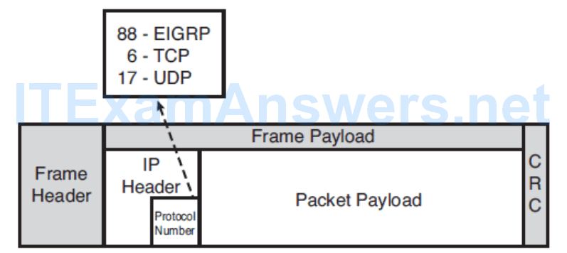
- EIGRP runs directly above the IP layer as its own protocol, numbered 88.
- RTP is the component of the EIGRP responsible for guaranteed, ordered delivery of EIGRP packets to all neighbors.
- It supports intermixed transmission of multicast or unicast packets.
EIGRP Operation Overview
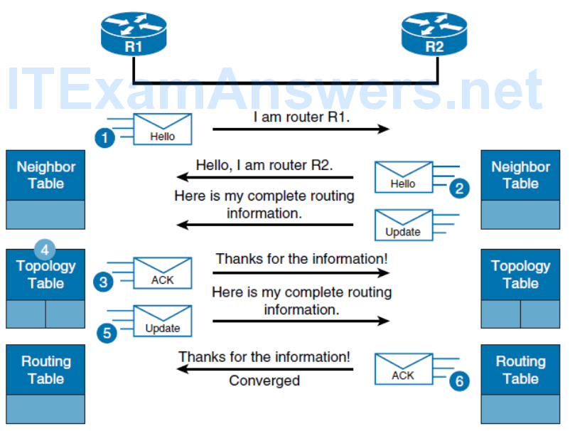
1. A new router (router R1 in this example) comes up on the link and sends a hello packet through all its EIGRP-configured interfaces.
2. Routers that are receiving the hello packet (R2) on one interface reply with update packets that contain all the routes that they have in their routing tables, except those that are learned through that interface (split horizon).
R2 sends an update packet to R1, but a neighbor relationship is not established until R2 sends a hello packet to R1. The update packet from R2 has the initialization bit set, indicating that this is the initialization process. The update packet includes information about the routes that the neighbor (R2) is aware of, including the metric that the neighbor is advertising for each destination.
3. After both routers have exchanged hellos and the neighbor adjacency is established, R1 replies to R2 with an ACK packet, indicating that it received the update information.
4. R1 assimilates all the update packets in its topology table. The topology table includes all destinations that are advertised by neighboring adjacent routers. It lists each destination, all the neighbors that can reach the destination, and their associated metric.
5. R1 sends an update packet to R2.
6. Upon receiving the update packet, R2 sends an ACK packet to R1
Configuring and Verifying Basic EIGRP for IPv4
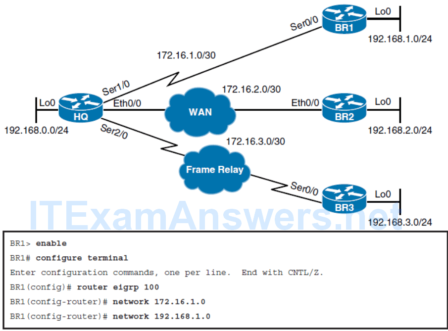

The router ID is a 32-bit value and is configured as any IPv4 address except 0.0.0.0 and 255.255.255.255. A unique 32-bit value should be configured for each router. If the router ID is not explicitly configured, the router will select the highest address of its loopback interfaces. If there is no loopback interface on the router, it will select the highest IPv4 address of any other active local interface. The router ID is not changed unless the EIGRP process is cleared or if the router ID is manually configured.
Verifying EIGRP Neighbor Relationships
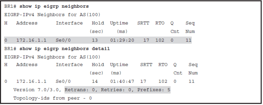
The command output shows you neighbor relationships established within an autonomous system:
- H column shows you the order in which peering sessions were formed.
- Address column shows you the IP address of the EIGRP peer.
- Interface column shows you the interface to which the peer is connected.
- Hold and Uptime columns show you the amount of time, in seconds, that the router will wait to hear from its EIGRP peer before declaring it unreachable and the amount time since the neighbor relationship formed, respectively.
- SRTT column shows the amount of time, in milliseconds, required for the router to send an EIGP packet to its neighbor and receive an acknowledgment for that packet.
- RTO or Retransmission timeout column shows you the amount of time the router waits before sending a packet from the retransmission queue.
- Q or Queue count column shows you the number of packets that the software is waiting to send. In case of network congestion, this number becomes greater than zero.
Additional information is displayed if you use the detail keyword:
- Retrans shows you the number of times that a packet has been retransmitted.
- Retries shows you the number of times an attempt was made to retransmit the packet.
- Prefixes is the number of prefixes received from the peer.
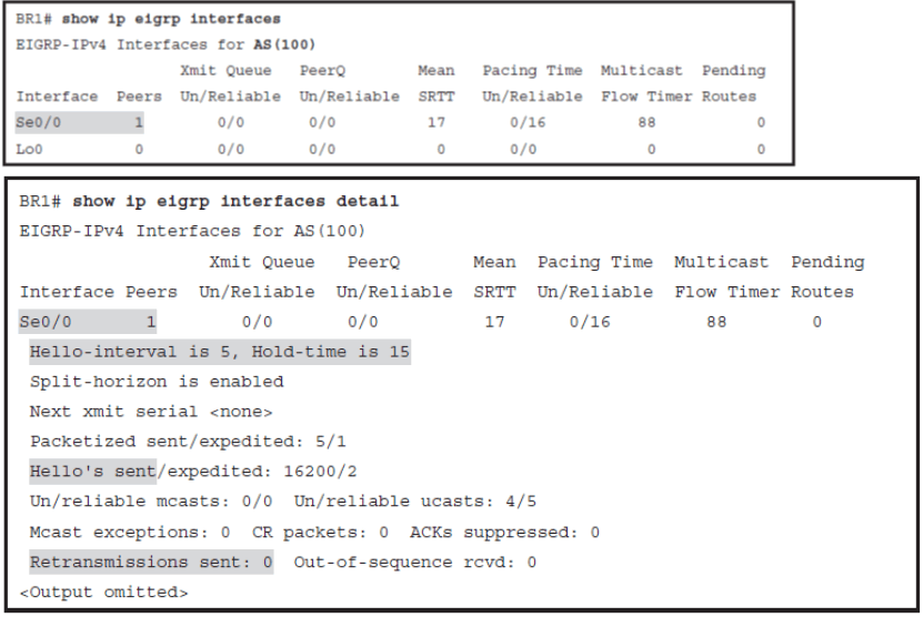
Verifying the EIGRP Interfaces
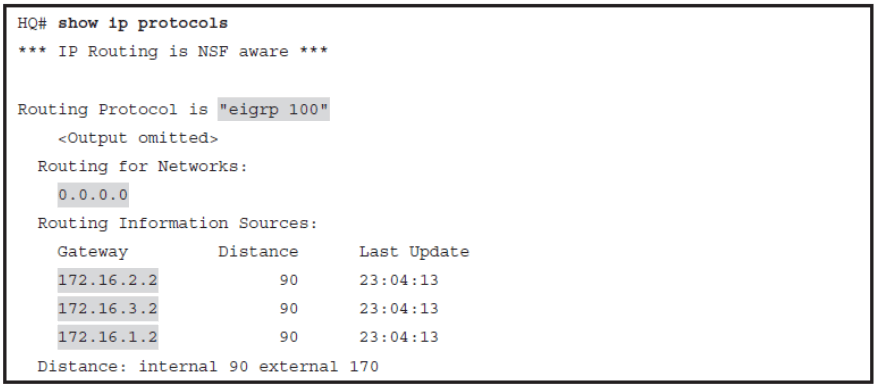
Verifying the EIGRP Networks
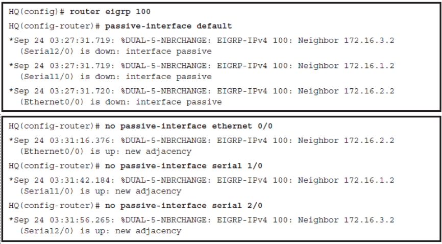
Configuring Passive Interfaces
Verifying Hello and Hold Timers
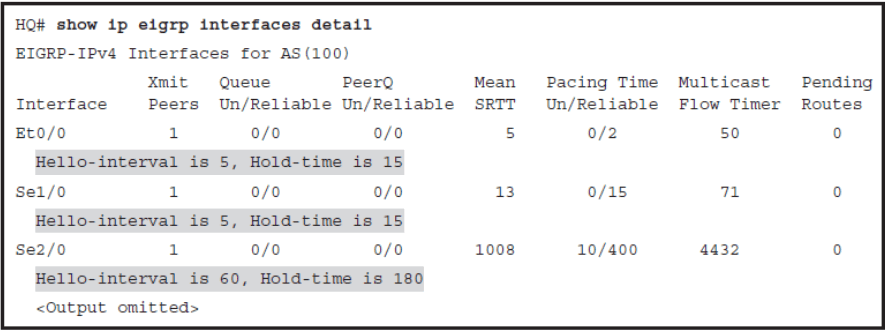
- Default Values in the pic
- Hello interval defaults to 5 seconds on all interfaces except on the low-speed NBMA links. Because Serial 2/0 uses Frame Relay with a default speed of 1544 Kbps, which is not greater than T1 speed, the hello timer defaults to 60 seconds. On NBMA links that are faster than T1, the hello timer defaults to 5 seconds
EIGRP Timers
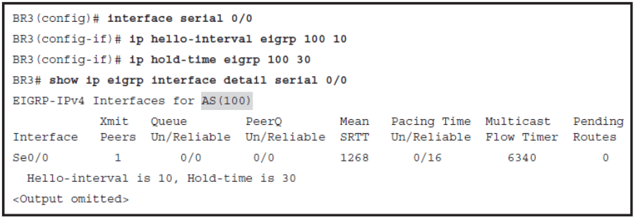
- EIGRP determines default timer values based on link type. If default values are not suitable for a specific network topology, you can manipulate values to improve convergence time.
- EIGRP hello and hold timers between neighbors do not need to be identical to successfully establish EIGRP neighbor relationship; however, asymmetrical timers may lead to flapping EIGRP neighbor relationships and network instability.
EIGRP Adjacencies in a Frame Relay Network
- When configuring EIGRP over point-to-multipoint subinterfaces, a single IP subnet is used.
- To emulate broadcast multiaccess network and enable EIGRP to send multicast packets over Frame Relay virtual circuits (VCs), you must add the broadcast keyword in the Frame Relay static mapping statement
- frame-relay map ip ip-address dlci broadcast
- When configuring EIGRP over point-to-point subinterfaces, a different IP subnet is used for each subinterface.
- These are logical interfaces that are emulating a leased line network and are a routing equivalent to point-to-point physical interfaces
EIGRP Adjacencies in a Layer 3 MPLS VPN Network
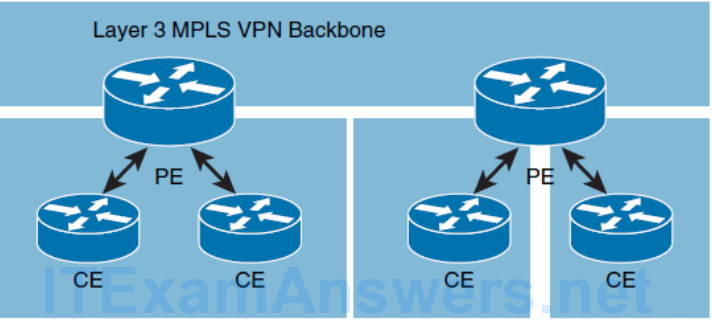
- Provider-edge (PE) routers participate in customer routing, guaranteeing optimum routing between customer sites.
- PE routers carry a separate set of routes for each customer, resulting in perfect isolation between the customers.
The Layer 3 MPLS VPN backbone looks like a standard corporate backbone to the CE routers. The CE routers run standard IP routing software and exchange routing updates with the PE routers that appear to them as normal routers in the customer network. The backbone routers in SP network are hidden from the view of the customer, and CE routers are unaware of the Layer 3 MPLS VPN. Therefore, the internal topology of the MPLS backbone is transparent to the customer.
EIGRP Adjacencies in a Layer 2 MPLS VPN Ethernet Network
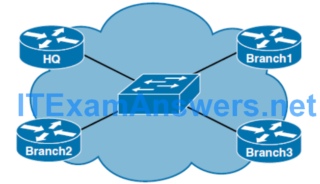
- Customer routers are located within single metropolitan area and they may be connected over the local Layer 2 MPLS VPN switch network. Customer traffic never passes through the SP backbone.
- Customer routers are located between several geographically distant areas that need to be connected over L2 MPLS VPN with point-to-point links through the SP backbone.
- Customer routers are located between several geographically distant areas that need to be connected over L2 MPLS VPN with multipoint links through the SP core. From the customer perspective SP network looks like a LAN switch.
- A point-to-point MPLS L2 VPN solution is where an MPLS backbone provides a Layer 2 Ethernet point-to-point connection between the customer routers. When establishing EIGRP neighbor relationships over point-to-point WAN Ethernet links, every point-to-point connection will be in its own IP subnet. This solution is not very scalable as the number of your branch offices rises and you want to ensure direct communication between branches.
- When you establish EIGRP neighbor relationships on the shared segment, every router on the segment will be neighbor with all other routers. In this topology, you will typically want to configure EIGRP authentication between neighbors to prevent unauthorized persons to add routers to your WAN network.
Building the EIGRP Topology Table
- EIGRP Neighbors Routing Information Exchange
- How EIGRP Chooses the Best Path through the Network
- Calculate EIGRP Metric
- Feasibility Condition prevents loops in EIGRP Networks
- Understand EIGRP Path Selection Process
EIGRP Neighbors Routing Information Exchange

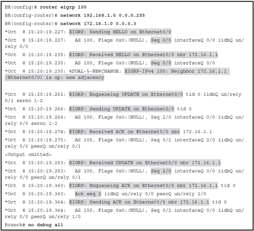
The numbers after the “Seq…” part of the debug output represent sequence and acknowledgment numbers. Looking at the debug output carefully, notice that each packet that is sent out reliabl has a sequence number. Acknowledgment that confirms a successful receipt of the packet must carry the same number as the received packet.
Verifying EIGRP Packet Traffic
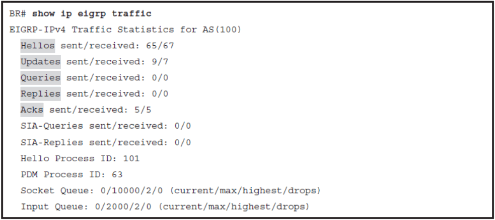
Verifying the EIGRP Routes
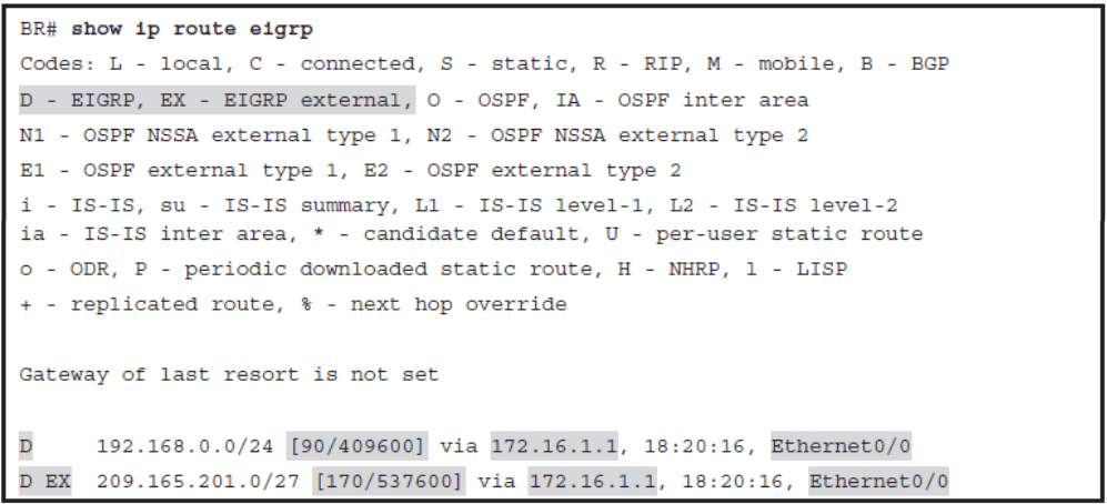
An internal route originated within an EIGRP autonomous system, meaning that a directly attached network that is configured in EIGRP is considered internal and is propagated through the EIGRP autonomous system. External routes, however, were learned by another routing protocol and redistributed to EIGRP. They are represented with code D EX.
Choosing the Best Path (DUAL)
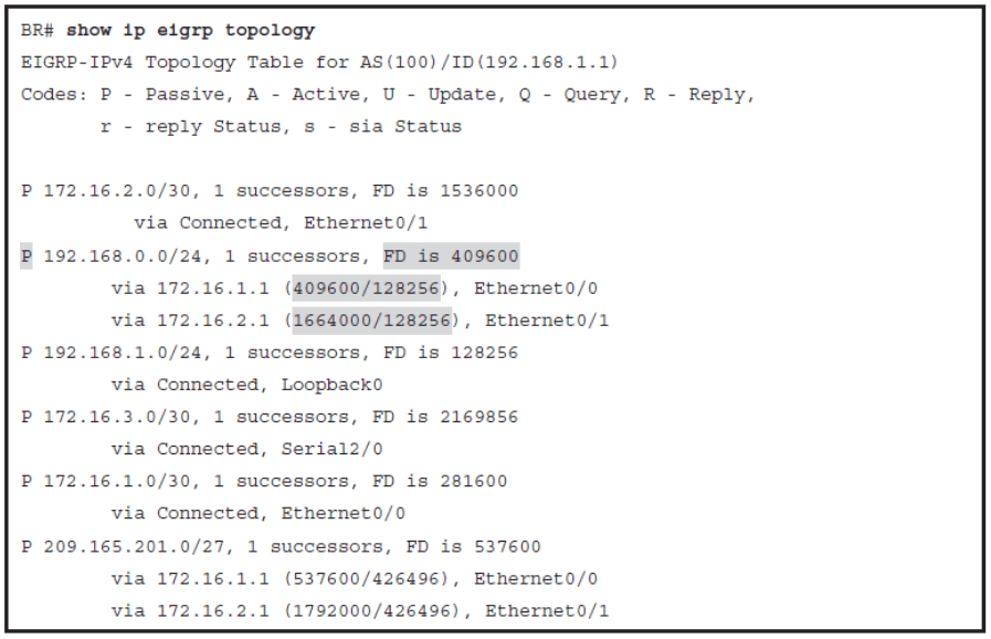
EIGRP uses DUAL to calculate the best path to a destination network. It uses the distance information, also known as a composite metrics to select efficient, loop-free paths
EIGRP Topology Table
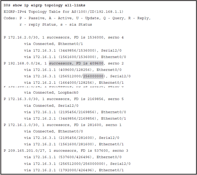
Explain FSM used by EIGRP
EIGRP Routing Information
- Only the routes that are used by EIGRP, the successor routes, get advertised.
- Subnets of directly connected interfaces on which EIGRP has been enabled using the network command
- Subnets learned by redistribution of routes into EIGRP from other routing protocols or routing information sources
- Redistribution is a method of taking routing information from one source and advertising it into another routing protocol.
- Redistribution is used in situations when multiple routing protocols are used in the same autonomous system, or when you want to include already-defined static routes into the selected routing protocol.
EIGRP Metric
EIGRP uses a composite metric to determine the best path to the destination. The metric’s value derives from a formula that can use the following parameters:
- Bandwidth: Least value of the bandwidth for all links between the local router and the destination.
- Delay: Cumulative delay obtained as sum of values of all delays for all links between the source and destination.
- Reliability: This value represents the worst reliability between source and destination (based on keepalives).
- Load: This value represents the worst load on the link between the source and the destination (based on the packet rate and the configured bandwidth of the interface).
You might find it in many books or online articles that maximum transmission unit (MTU) is also used in EIGRP metric calculations. Although it is true that MTU value is exchanged in the routing updates together with other metric components, it is never used for the metric calculation. It is only used as a tie-breaker, when the router needs to ignore some equal-cost paths to the same destination, because of too many equal-cost paths. In such cases, the route with the highest minimum MTU is preferred.
EIGRP Metric Calculation
Metric = [(K1 * Bandwidth + [(K2 * Bandwidth) / (256 – Load)] + K3 * Delay) * K5/(K4 + Reliability)] * 256
- With the default K-Values K1=1, K2=0, K3=1, K4=0, K5=0
- Metric = (Bandwidth + Delay) * 256
- Note that changing the K values is not recommended.
The format of the delay and bandwidth values that are used for EIGRP metric calculations is different from those that are displayed by the show interface command. The EIGRP delay value is the sum of the delays in the path, in tens of microseconds, whereas the show interface output displays the delay in microseconds. The EIGRP bandwidth is calculated using the minimum bandwidth link along the path, in kilobits per second. The value 10 7 is divided by this value. Sum of bandwidth and delay is multiplied by 256 to ensure backward compatibility with the EIGRP predecessor IGRP.
EIGRP Metric Calculation Example
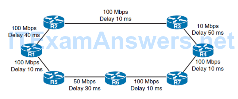
- Bandwidth = (10^7 / Least bandwidth in kilobits per second)
- Delay = microseconds/10
- Metric = (Bandwidth + Delay) * 256
- Bandwidth = (10,000,000 / 10,000) = 1,000
- Delay = [4000 + 1000 + 5000] = 10000 [tens of microseconds]
- Metric = (1000 + 10,000) * 256 = 2,816,000
- Bandwidth = (10,000,000 / 10,000) = 1,000
- Delay = [4000 + 1000 + 5000] = 10000 [tens of microseconds]
- Metric = (Bandwidth + Delay) * 256
- Metric = (1000 + 10,000) * 256 = 2,816,000
EIGRP Successor and FS Example
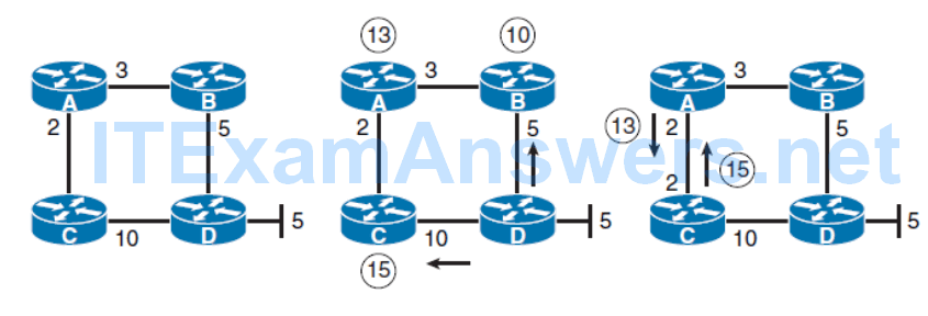
Assume for a moment that the split horizon has been disabled on router C on the link between router A and C. When router A advertises a best path metric of 13 from router A to C, router C may advertise the same route back to router A with an increased metric of 15. In this case, router A will not know whether router C has an alternate path to the LAN network of router D or whether it is advertising the route for the best path just back to router A. Because RD over router C is greater than FD of the best path, router A will not rely on the RD from router C. This is how router A ensures that the EIGRP domain stays loop free.
EIGRP Path Calculation Example
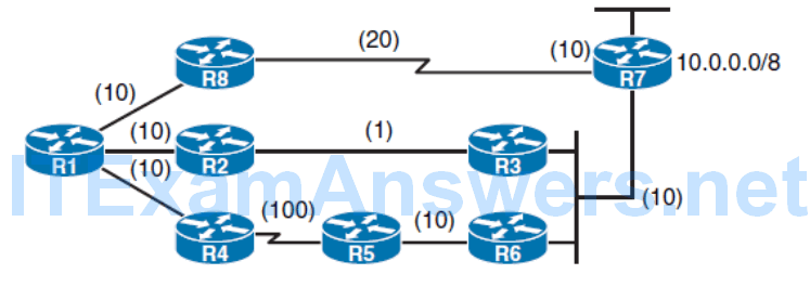
Reported Distance

Fisable Distance

Successor
Fisable Successor

Optimizing EIGRP Behavior
- EIGRP queries
- Describe how stub routing can be used to reduce the amount of queries when EIGRP goes active
- EIGRP stuck-in-active issue
- Explain how using summary routes lessen the impact of query scope when EIGRP goes active
- Describe load-balancing options with EIGRP
EIGRP Queries
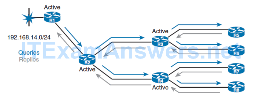
- When a router loses a route and does not have a feasible successor in its topology table, it looks for an alternative path to the destination.
- This is known as going active on a route.
Active Route
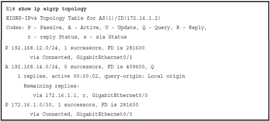
Two major solutions exist to optimize the query propagation process and to limit the amount of unnecessary EIGRP load on the links.
- Route summarization
- EIGRP stub routing
EIGRP Stub Routers
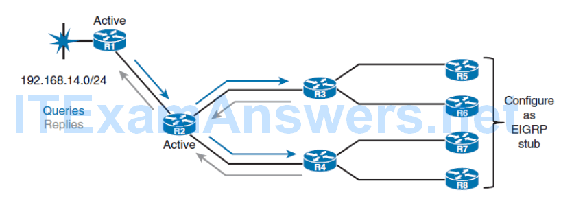
- Routers configured as stubs do not forward EIGRP learned routes to other neighbors, and more importantly, nonstub routers do not send query messages to stub routers.
- This saves CPU cycles and bandwidth and speeds up convergence.
EIGRP Stub Options
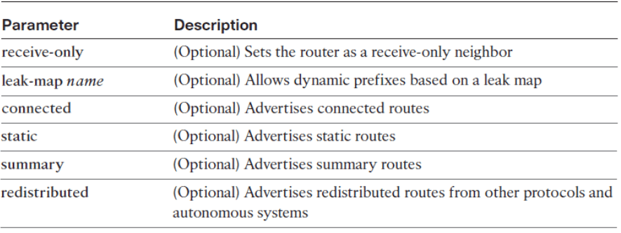
- To configure a router as a stub use the eigrp stub command in router configuration mode or address family configuration mode.
- To disable the EIGRP stub routing feature, use the no form of this command.
- A router that is configured as a stub shares information about connected and summary routes with all neighboring routers by default.
- You can combine all stub options except for receive-only to achieve desired combination of advertised routes.
- The connected option permits the EIGRP stub router to advertise all connected routes for interfaces that are matched with an EIGRP network command. This option is enabled by default and is the most widely practical stub option.
- The summary option permits the EIGRP stub router to send summary routes. You can create summary routes manually, or you can create them automatically by enabling auto-summary at a major network boundary router.
- The static option permits the EIGRP stub router to advertise static routes. You still need to redistribute static routes into EIGRP using the redistribute static command.
- The redistribute option permits the EIGRP stub router to advertise all redistributed routes, as long as redistribution is configured on the stub router using the redistribute command.
- The receive-only option restricts the stub router from sharing any of its routes with any other router within an EIGRP autonomous system. This option does not permit any other option to be specified because it prevents any type of route from being sent.
The receive-only option is rarely used. Two examples are when a router has a single interface or if Network Address Translation (NAT) with Port Address Translation (PAT) is configured, so all hosts are hidden behind a single WAN interface.
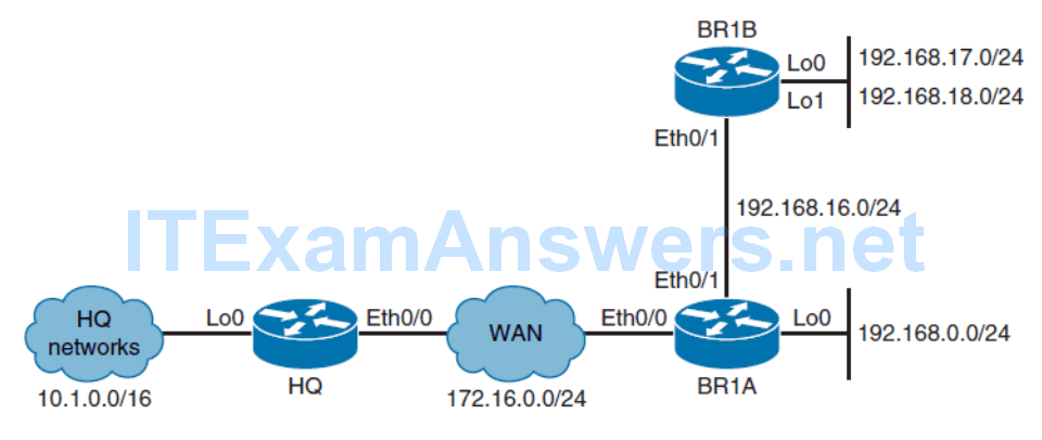
EIGRP Topology for Configuring Stub Routers
Initial Configuration (HQ)
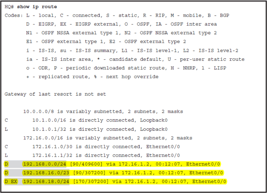
Duas internas EIGRP (um sumario e uma connected) e Uma Externa (estatica distribuida do BR1A)
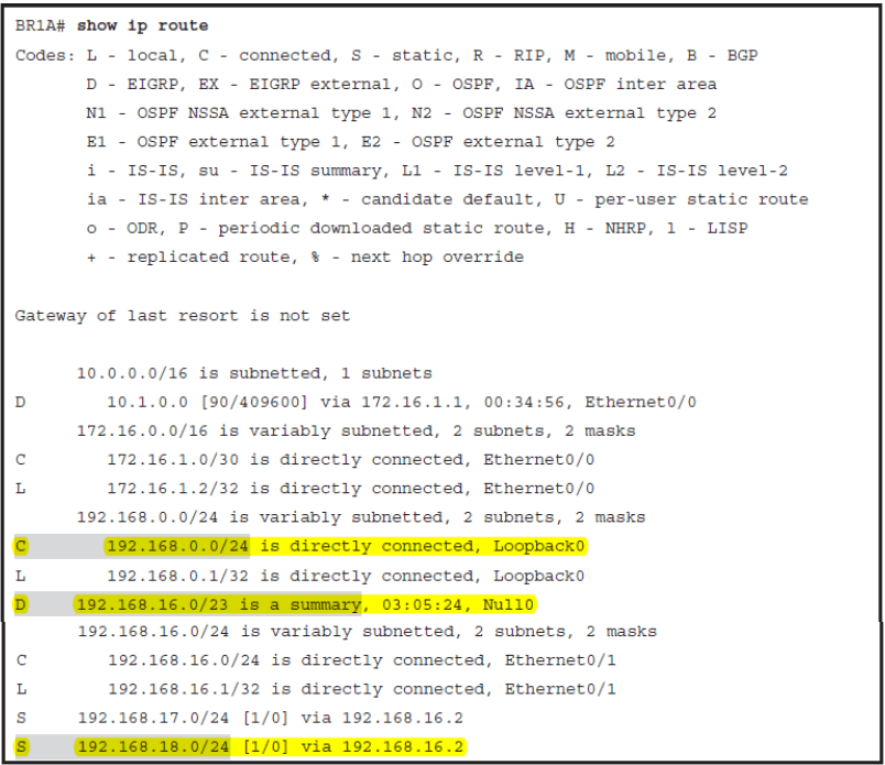
Initial Configuration (BR1A)
Configuring an EIGRP Stub Router
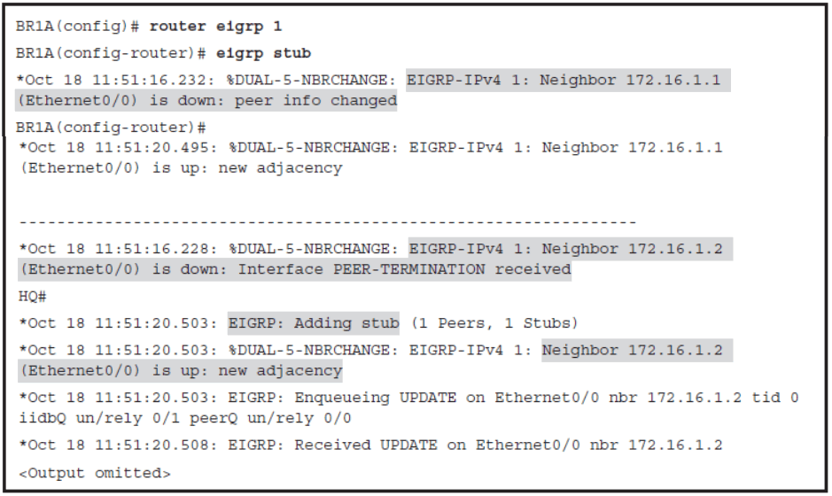
When the BR1A router is configured as a stub, the EIGRP adjacency needs to be reestablished.
BR1A Verified as an EIGRP Stub on HQ
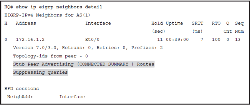
Notice in Example 2-37 that router HQ sees router BR1A a stub router. By default, stub routers advertise only connected and summary routes to their neighbors; all other routes are filtered. Also notice the information about the queries. HQ is now suppressing them because BR1A is configured as stub.
Change in the routing tables
- BR1A Routing Table stays exactly the same
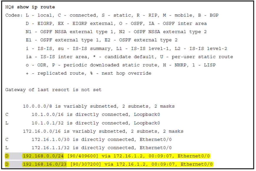
The external route disappears because by default only connected and summary are announced from the stub router
Configuring an EIGRP Connected Stub
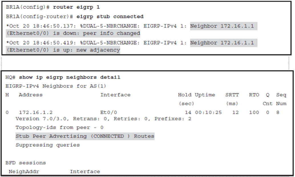
Change in the routing tables
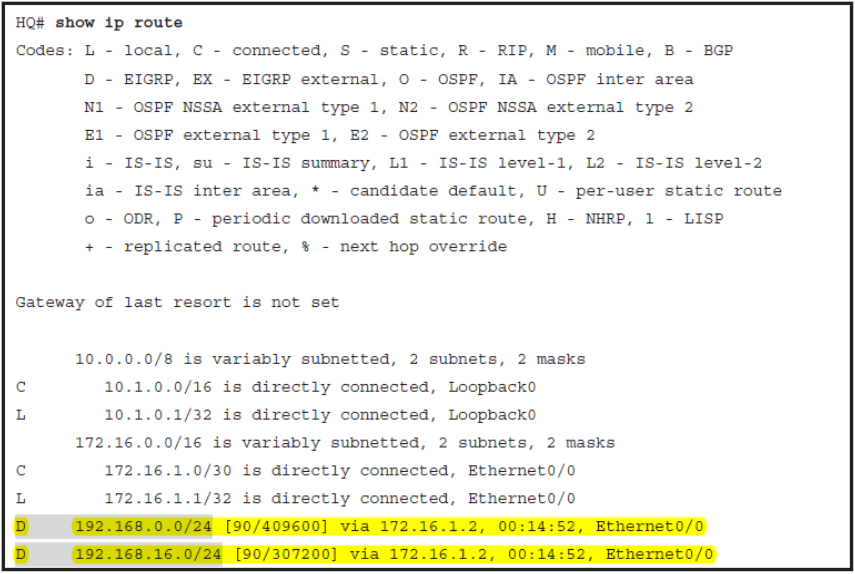
The summary route has disappear and only the connected routes are presented in the HQ Routing Table.
Configuring an EIGRP Receive-Only Stub
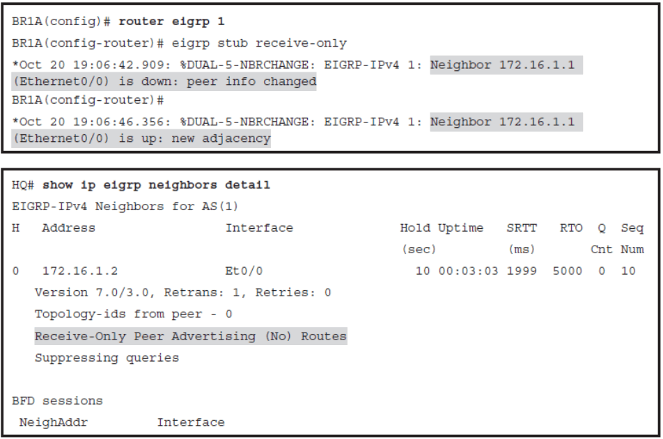
Change in the routing tables
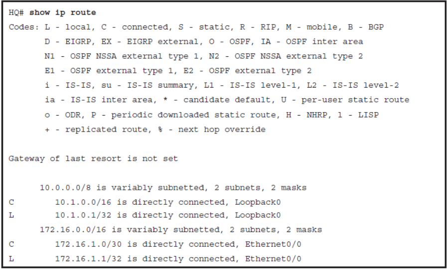
Notice that all dynamic EIGRP routes have disappeared from the HQ’s routing table. Router BR1A is configured as receive-only stub and is not advertising any routes to HQ. This stub option can be useful in cases when all hosts behind router BR1A would be translated using NAT with PAT.
Stuck in Active
- Once a route goes active and the query sequence I initiated, it can only come out of the active state and transition to the passive state when it receives a reply for every generated query.
- If the router does not receive a reply to all the outstanding queries within 3 minutes (the default time), the route goes into the stuck-in-active (SIA) state.
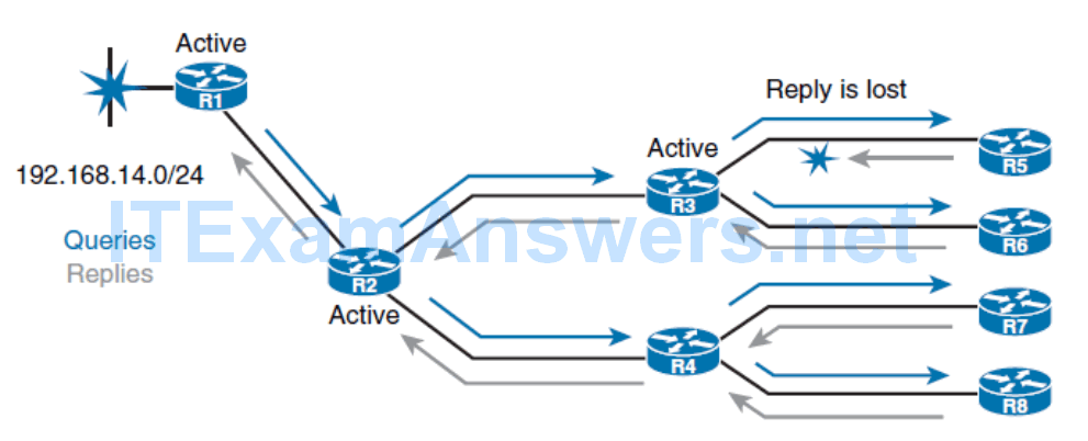
- This timer is called the active timer.
- Once the active timer expires, the neighbor relationship is reset.
- This setting causes the router to go active on all routes that were known through the lost neighbor and to re-advertise all the routes that it knows to the lost neighbor.
- Two new additional EIGRP packets were introduced to overcome the described limitation.
- When no reply to a query is received, EIGRP sends an SIA query packet when the active timer is halfway through (after 90 seconds).
- This enables the neighboring router to respond with a SIA reply and confirm to the upstream router that it is still searching for a replacement route.

- Resetting a neighbor relationship due to a lost reply message is very aggressive behavior. In large environments with slower links, it can cause long convergence times and network instability.
- Two new additional EIGRP packets were introduced to overcome the described limitation. When no reply to a query is received, EIGRP sends an SIA query packet when the active timer is halfway through (after 90 seconds). This enables the neighboring router to respond with a SIA reply and confirm to the upstream router that it is still searching for a replacement route.
- R1 queries downstream R2 (with an SIA query) at the midway point of the active timer about the status of the route.
- R2 responds (with an SIA reply) that it still is searching for a replacement route.
- Upon receiving this SIA reply response packet, R1 validates the status of R2 and does not terminate the neighbor relationship.
- Meanwhile, R2 will send up to three SIA queries to R3. If they go unanswered, R2 will terminate the neighbor relationship with R3. R2 will then update R1 with an SIA reply indicating that the network 192.168.14.0/24 is unreachable.
- R1 and R2 will remove the active route from their topology tables. The neighbor relationship between R1 and R2 remains intact.
Reducing Query Scope by Using Summary Routes
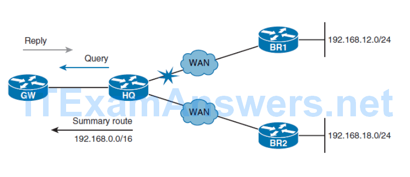
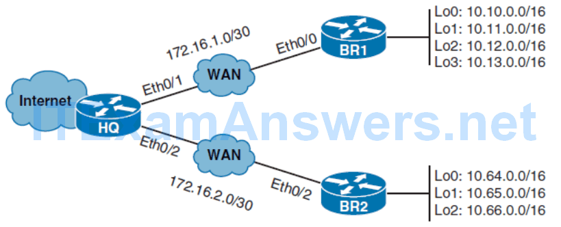
Configuring EIGRP Summarization
- Implementing EIGRP summarization provides several benefits. Not only does it reduce the size of routing tables on the routers, but it also limits the query scope.
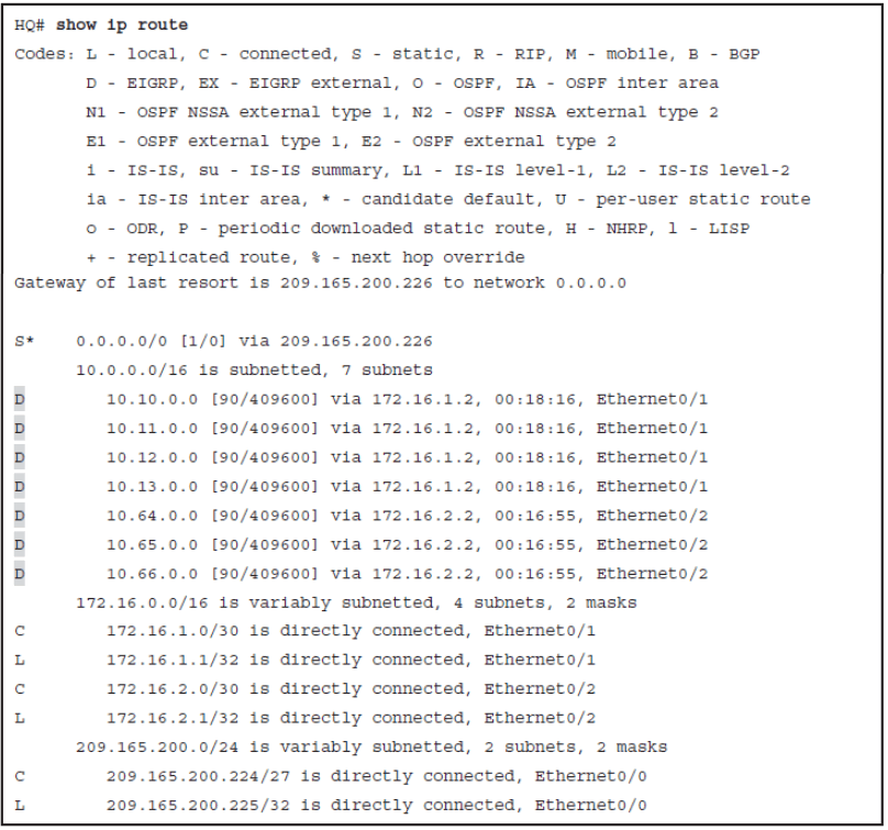
HQ RT without summarization
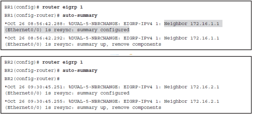
Enable auto-summarization in the BRs
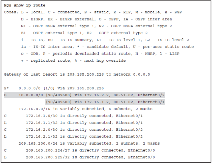
HQ RT after summarization
Testing Connectivity from HQ to the Summarized Network
- Because both routes have the same cost, HQ will load balance between these two routes causing unreachability issues.

- This occurs because both remote networks belong to the same classfull, creating a discontinuous network connection.
Configuring Manual Summarization
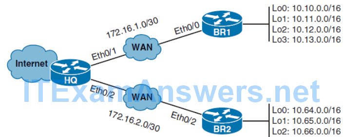

HQ BR1A after Manual Summarization
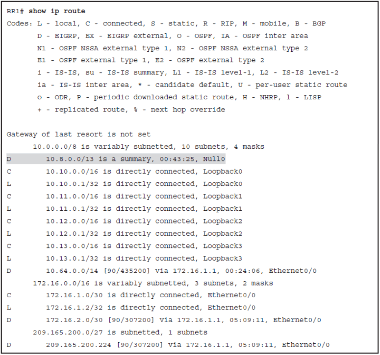
HQ RT after Manual Summarization
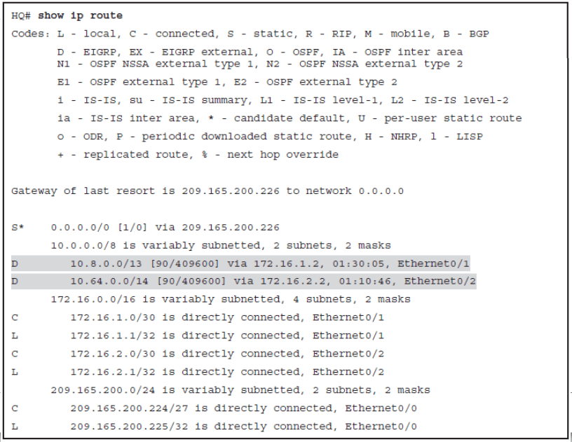
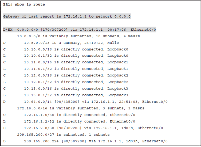
Obtaining Default Route
- The candidate can be a statically configured default route defined locally with the command ip route 0.0.0.0 0.0.0.0 next-hop | interface .
- The candidate can alsobe a default route announced by the dynamic routing protocol. EIGRP can redistribute statically defined default routes by using the redistribute static configuration command.
- In addition, any classful network residing in the local routing table can become a default candidate when used with the ip default-network configuration command.
- The command attaches an exterior flag to any classful EIGRP route, thus making it a candidate for a default route.
Redistributing Static
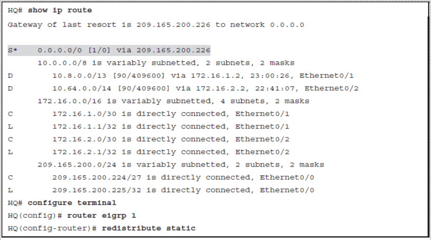
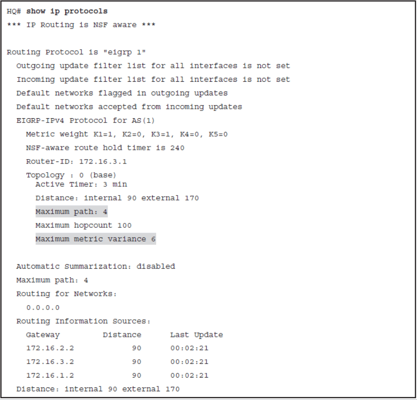
Load Balancing with EIGRP
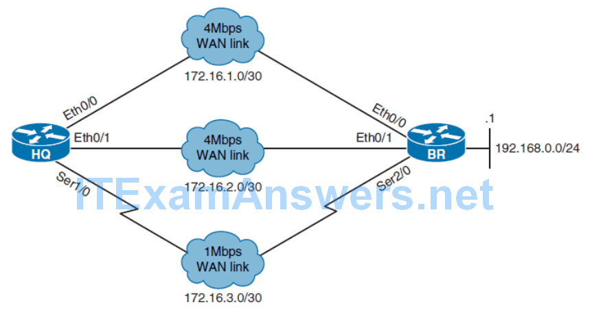
- EIGRP can distribute traffic over multiple links leading to the same destination to increase the effective network bandwidth.
- It supports load balancing over equal-metric paths and also over unequal-metric paths.
- EIGRP enables load balancing between a maximum of four equal-metric paths by default.
- The maximum number of parallel routes that an IP routing protocol can support can be changed using the maximum-paths router configuration command.
- When a packet is process switched, load balancing over equal-metric paths occurs on a per-packet basis.
- When packets are fast switched, load balancing over equal-metric paths occurs on a per-destination basis.
- Cisco Express Forwarding (CEF) switching, enabled by default, supports both per-packet and per-destination load balancing.
- Load balancing over unequal-metric links is disabled by default.
- Only feasible successor paths can be included in the EIGRP load-balancing, to ensure the topology stays loop free.
Configuring EIGRP Load Balancing
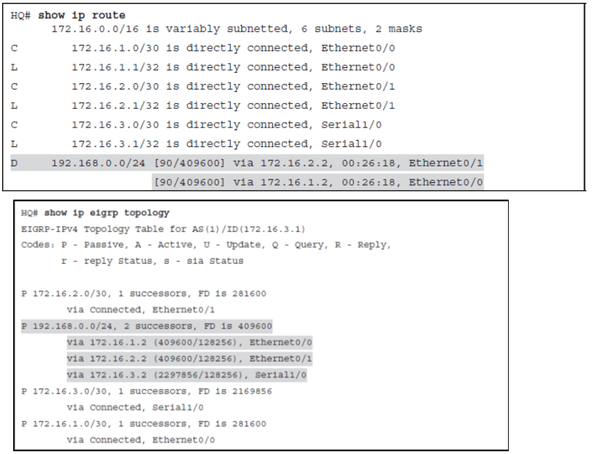
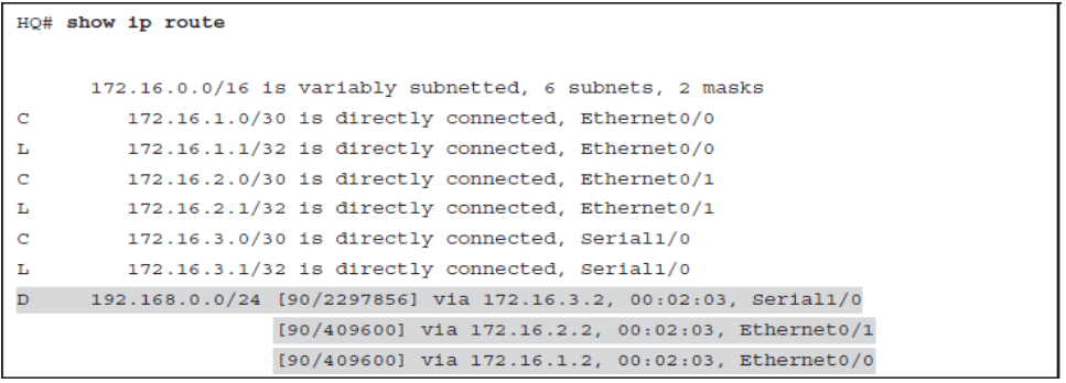
Load Balancing Across Unequal-Metric Paths
- The route must be loop free. This condition is satisfied when the advertised distance is less than the total distance, or when the route is a feasible successor.
- The metric of the route must be lower than the metric of the best route (the successor) multiplied by the variance that is configured on the router.

Note: EIGRP does not load-share between multiple routes; it only installs the routes in the local routing table. The local routing table then enables switching hardware or software to load share between the multiple paths.
Verifying EIGRP Load-Balance
Configuring EIGRP for IPv6
- Differences and Similarities of EIGRP for IPv4 and IPv6
- Configure Basic EIGRP for IPv6 Settings
- Configure and Verify EIGRP for IPv6 Summarization
- Verify basic EIGRP for IPv6 settings
Overview of EIGRP for IPv6
- EIGRP for IPv6 uses IPv6 prefixes and lengths rather than IPv4 subnets and masks.
- To establish EIGRP for IPv6 neighbor relationship, it uses IPv6 link-local addresses. EIGRP for IPv4 does not have the concept of link-local address.
- EIGRP uses built-in authentication features of the IPv6 protocol rather than protocol specific authentication implemented with IPv4 to guarantee message authentication.
- To transport routing information, EIGRP for IPv6 encapsulates IPv6 prefixes in the IPv6 messages, not in the IPv4 packets.
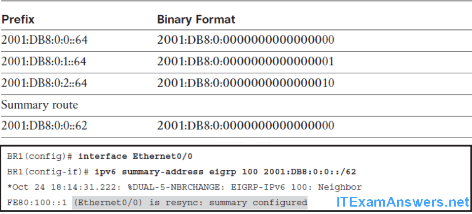
- IPv6 has no concept of the classful network; so when you use EIGRP for IPv6, there is no automatic summarization at the class boundaries. The only way to summarize IPv6-advertised prefixes is through manual summarization.
- If IPv4 address is not configured on the router, EIGRP for IPv6 requires an EIGRP router ID before it can start running. In IPv4, if you do not configure the EIGRP router ID, the router will automatically assign it using the highest loopback or the highest active interface IPv4 address.
- EIGRP for IPv6 under a specific interface intended to send and receive routing protocol messages. In EIGRP for IPv4, you configure interfaces under the routing protocol configuration mode.
- EIGRP for IPv6 uses assigned dedicated multicast address FF02::A, whereas EIGRP for IPv4 uses dedicated multicast address 224.0.0.10.
Configuring and Verifying EIGRP for IPv6
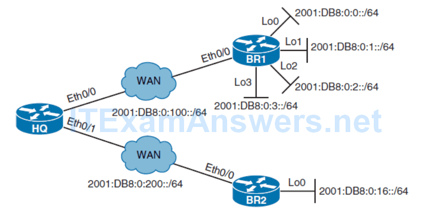

The ipv6 unicast-routing command enables the router:
- To be configured for static and dynamic IPv6 routing
- To forward IPv6 packets
- To send ICMPv6 router advertisement messages
If you have configured IPv6 routing protocols on the router, the command no ipv6 unicast-routing will remove all IPv6 routing protocol entries from the IPv6 routing table.

- EIGRP for IPv6 has a shutdown feature.
- The routing process must be in “no shutdown” mode for EIGRP for IPv6 processing.
- No shutdown is the default on later IOSs. If necessary, you might have to issue the no shutdown command in EIGRP for IPv6 configuration mode.
- Another important parameter is the EIGRP router ID.
- Like EIGRP for IPv4, EIGRP for IPv6 uses a 32-bit router ID.
- If no IPv4 active address is configured on the router, the router will not be able to choose the EIGRP router ID.
- In this case, you must configure the router ID manually under the EIGRP routing process to make EIGRP for IPv6 operational.
Each router participating in EIGRP for IPv4 and IPv6 is identified by a 32-bit router ID. Routers will try to determine the router ID based on the highest configured IPv4 address on a loopback interface or, if no loopback is configured, based on the highest configured IPv4 address on a physical interface. If no IPv4 interface is configured on the router, the router ID must be manually defined to make EIGRP for IPv6 operational.
- Before you enable EIGRP for IPv6 on the interface, it must have a valid IPv6 link-local address.
- EIGRP for IPv6 uses link-local addresses to form EIGRP neighbor relationships.

Link-Local Importance for IPv6 Routing
- The link-local address is automatically created on an interface when the interface obtains a global IPv6 address, either manually or dynamically.
- IPv6 can also be enabled on an interface without assigning a global unicast address using the interface mode command ipv6 enable.
- In both cases, IPv6 link-local address will be assigned automatically to the interface using EUI-64.
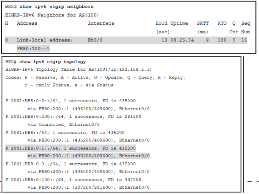
Verifying EIGRP for IPv6 Neighbor Adjacency and Topology Table
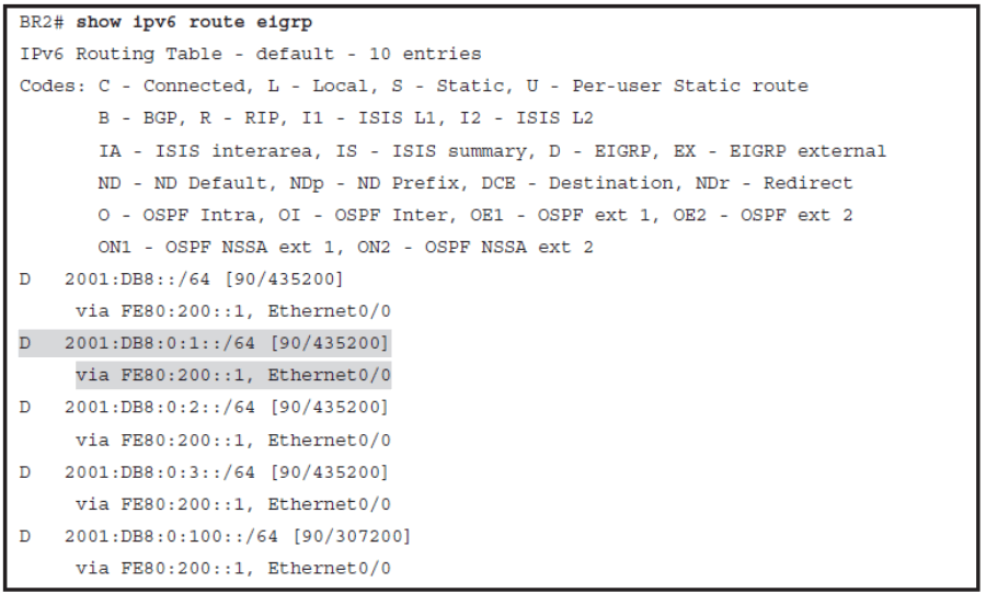
Verifying EIGRP for IPv6 Routing Table
Configuring EIGRP for IPv6 Summary Route
Named EIGRP Configuration
- Describe how EIGRP named configuration is different from the classic EIGRP configuration
- Explain what is configured under different address family configuration modes
- Compare examples of classic and named EIGRP configuration
- Configuring and verifying EIGRP for IPv6
- Configuring EIGRP for both IPv4 and IPv6 on the same router can become a complex task because configuration takes place using different router configuration modes
- A newer configuration enables the configuration of EIGRP for both IPv4 and IPv6 under a single configuration mode.
- EIGRP named configuration helps eliminate configuration complexity that occurs when configuring EIGRP for both IPv4 and IPv6
- EIGRP named configuration is available in Cisco IOS Release 15.0(1)M and later releases.
Configuring Named EIGRP
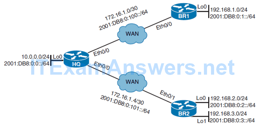
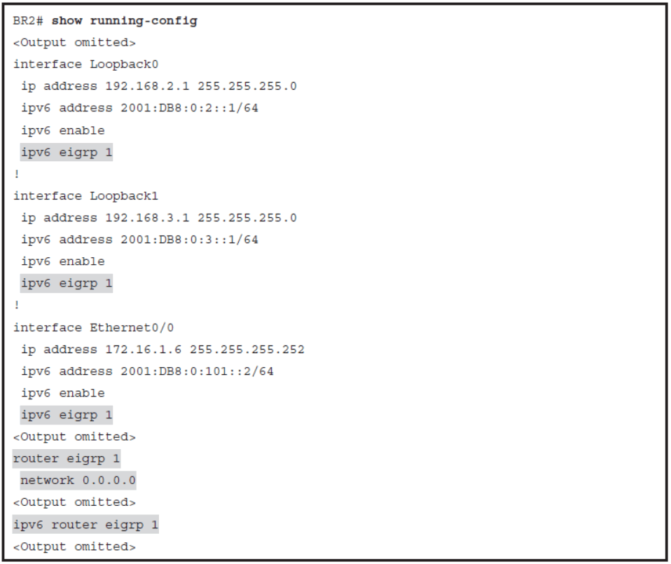
Address Families
- EIGRP named configuration mode uses the global configuration command router eigrp virtual-instance-name.
- Both EIGRP for IPv4 and IPv6 can be configured within this same mode.
- EIGRP supports multiple protocols and can carry information about many different route types.
- Named EIGRP configuration organizes specific route types under the same address family.
- IPv4 unicast and IPv6 unicast are two of the most commonly used address families.
EIGRP for IPv4 Address Family

address-family ipv4 [ multicast ] [ unicast ] [ vrf vrf-name ] autonomous-system as-number
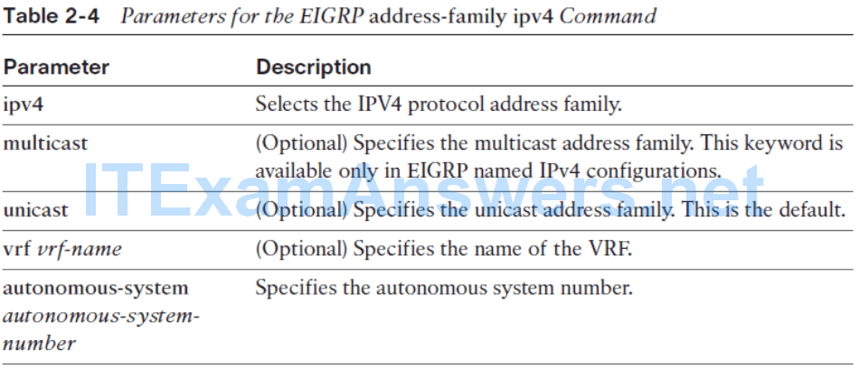
- The address-family command enables the IPv4 address family and starts EIGRP for the defined autonomous system.
- In IPv4 address family configuration mode, you can enable EIGRP for specific interfaces by using the network command, and you can define some other general parameters such as router-id or eigrp stub.
- Unless specified otherwise, address family is by default defined as unicast address family used the exchange unicast routes.

Note: The EIGRP address-family command is also available under classic or basic EIGRP for both IPv4 and IPv6. Configuration is similar to named EIGRP.
EIGRP for IPv6 Address Family

address-family ipv6 [ unicast ] [ vrf vrf-name ] autonomous-system as-number

Note The EIGRP autonomous system numbers for the IPv4 and IPv6 address families do not have to be the same. The only requirement is that the same autonomous system number for IPv4 and the same autonomous system number for IPv6 be used by all routers in the same EIGRP routing domain.
- IPv6 EIGRP neighbor relationship gets established as soon as you define the IPv6 address family.
- All IPv6-enabled interfaces are automatically included in the EIGRP for IPv6 process.
- The IPv6 address family configuration will show up in the running configuration as a unicast address family by default.
- You can configure or remove individual interfaces from the EIGRP for IPv6 process by using the af-interface interface-type interface number command in address family configuration mode
af-interface { default | interface-type interface number }

Disabling EIGRP for IPv6 on an Interface

Named EIGRP Final Config
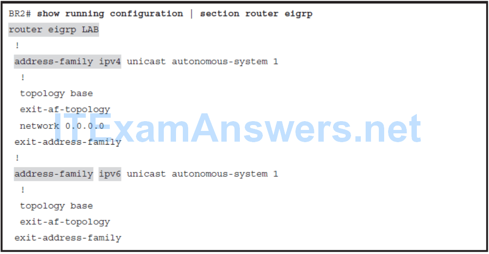
EIGRP Summarization in Named Configuration

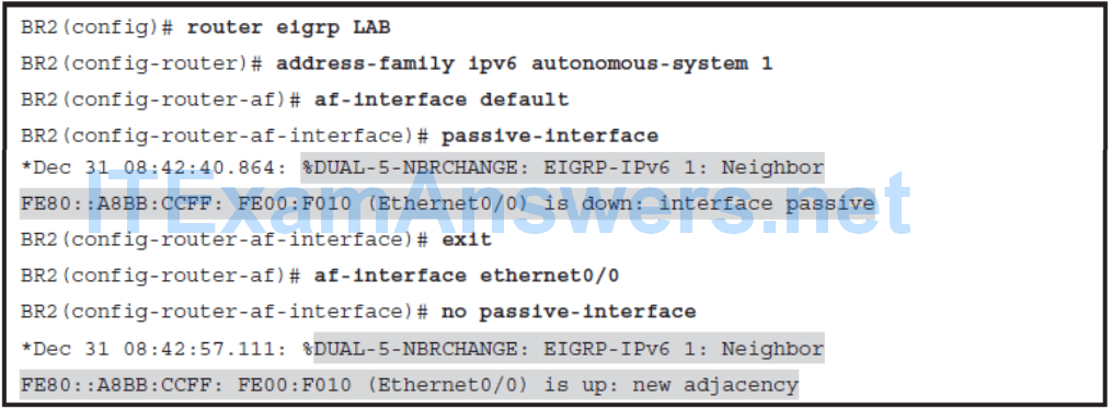
Configuring IPv6 Passive Interfaces
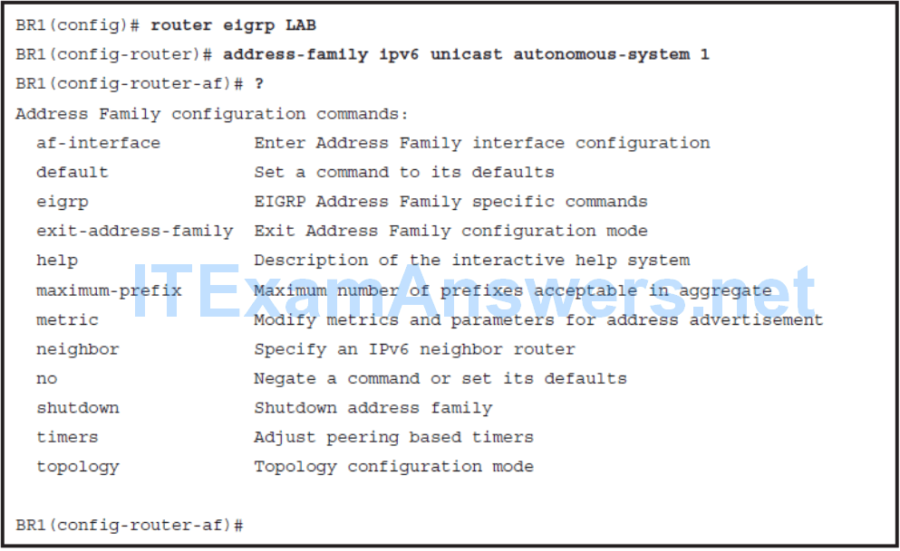
Named EIGRP Configuration Modes
Three different configuration modes:
Address family configuration mode
- General EIGRP configuration commands for selected address family are entered under address family configuration mode. Here you can configure the router ID and define network statements and also configure router as an EIGRP stub.
- Address family configuration mode gives you access to two additional configuration modes: address family interface configuration mode and address family topology configuration mode.
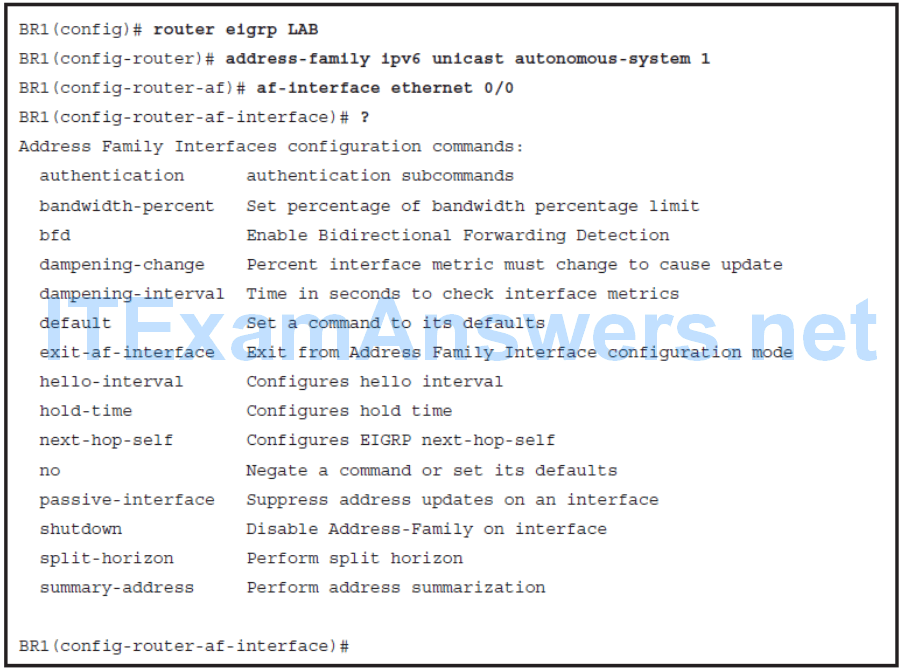
Address family interface configuration mode
- You should use address family interface configuration mode for all those commands that you have previously configured directly under interfaces. Most common options are setting summarization with the summary-address command or marking interfaces as passive using passive-interface command. You can also modify default hello and hold-time timers.
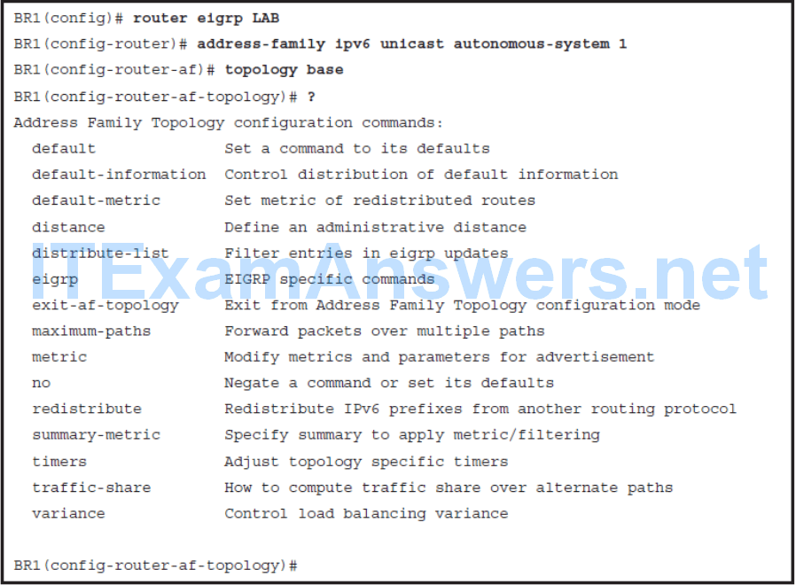
Address family topology configuration mode
- Address family topology configuration mode gathers all configuration options that directly impact the EIGRP topology table. Here you can set load-balancing parameters such as variance and maximum-paths, or you can redistribute static routes using the redistribute command.
Address Family Configuration Mode
Address Family Interface Configuration Mode
Address Family Topology Configuration Mode
Chapter 2 Summary
- EIGRP is an advanced distance vector protocol.
- EIGRP uses RTP for reliable, guaranteed delivery of packets.
- Hello and hold timers can be adapted to influence network convergence.
- IGRP adapts well to various technologies such as Frame Relay, Layer 3 MPLS VPN, and Layer 2 MPLS VPN.
- EIGRP uses hello, update, query, reply, and acknowledgment packets.
- EIGRP uses a composite metric that is by default based on bandwidth and delay.
- Reported distance is the metric value reported by the neighboring router.
- Feasible distance is the lowest distance to a destination from the perspective of the local router.
- Alternative path must satisfy the feasibility condition to become a feasible successor.
- The reported distance of an alternate path must be less than the feasible distance.
- When a route is lost and no feasible successor is available, queries are sent to all neighboring routers on all interfaces.
- EIGRP stub configuration improves network stability and reduces resource utilization.
- Summarization decreases the size of the IP routing table and optimizes exchange of routing information.
- EIGRP performs equal-cost load balancing.
- To support unequal-cost load balancing, a variance parameter must be configured.
- EIGRP for IPv6 uses IPv6 link-local addresses to form neighbor relationships.
- EIGRP for IPv6 supports only manual prefix summarization.
- To configure EIGRP for IPv6, you must define the routing process and configure interfaces participating in EIGRP routing.
- EIGRP for IPv6 verification commands have similar syntax to EIGRP for IPv4 commands.
- Classic EIGRP configuration is divided over different configuration modes.
- Named EIGRP configuration gathers EIGRP configuration in one place.
- Named EIGRP configuration unifies configuration commands for different address families.
- Named EIGRP configuration is hierarchically organized using three address family configuration modes.
- The same verification commands for classic EIGRP are used to verify named EIGRP configuration.
