Objectives
This chapter covers the following topics:
- Securing the Management Plane on Cisco Routers
- Describing Routing Protocol Authentication
- Configuring Authentication for EIGRP
- Configuring Authentication for OSPFv2 and OSPFv3
- Configuring Authentication for BGP peers
- Configuring VRF-lite
A router’s operational architecture can be categorized into three planes:
- Management plane
- This plane is concerned with traffic that is sent to the Cisco IOS device and is used for device management. Securing this plane involves using strong passwords, user authentication, implementing role-based command-line interface (CLI), using Secure Shell (SSH), enable logging, using Network Time Protocol (NTP), securing Simple Network Management Protocol (SNMP), and securing system files.
- Control plane
- This plane is concerned with packet forwarding decisions such as routing protocol operations. Securing this plane involves using routing protocol authentication.
- Data plane
- This plane is also known as the forwarding plane because it is concerned with the forwarding of data through a router. Securing this plane usually involves using access control lists (ACLs).
Securing the Management Plane on Cisco Routers
Securing the Management Plane on Cisco Routers
Device hardening tasks related to securing the management plane of a Cisco router, including the following:
- Following the router security policies
- Securing management access
- Using SSH and ACLs to restrict access to a Cisco router
- Implement logging
- Securing SNMP
- Backup configurations
- Using network monitoring
- Disabling unneeded services
Securing the Management Plane
Step 1.
- Follow the written router security policy.
- The policy should specify who is allowed to log in to a router and how, who is allowed to configure and update the router, or who is allowed to perform logging and monitoring actions.
- The policy should also specify the requirements for passwords that are used to access the router.
Step 2.
- Secure physical access.
- Place the router and physical devices that connect to it in a secure locked room that is accessible only to authorized personnel.
- The room should also be free of electrostatic or magnetic interference, have fire suppression, and controls for temperature and humidity.
- Install an uninterruptible power supply (UPS) and keep spare components available.
- This reduces the possibility of a network outage from power loss.
Step 3.
- Use strong encrypted passwords
- Use a complex password with a minimum of eight characters.
- Enforce a minimum length using the security password min-length global configuration command.
- Strong passwords should generally be maintained and controlled by a centralized authentication, authorization, and accounting (AAA) server.
- Some local passwords and secret information may be required, for local fallback in case AAA servers become unavailable, such as special-use usernames, secret keys, and other password information.
- Such local passwords should be properly encrypted to secure them from prying eyes.
Step 4.
- Control the access to a router.
- Console and auxiliary ports: These ports are used to gain access when a physical connection to the router is available in the form of a terminal.
- vty lines: Access to a router using SSH or Telnet is by far the most common administrative tool. For this reason, vty access should be protected using only SSH from authorized IP addresses identified in an ACL.
Step 5.
- Secure management access
- Only authorized individuals should have access to infrastructure devices.
- For this reason, configure authentication, authorization, and accounting (AAA) to control who is permitted to access a network (authenticate), what they can do on that network (authorize), and audit what they did while accessing the network (accounting).
- Authentication can be performed locally or by using a AAA authentication server.
Step 6.
- Use secure management protocols.
- Always use secure management protocols including SSH, HTTPS, and SNMPv3.
- If unsecure management protocols such as Telnet, HTTP, or SNMP must be used, then protect the traffic using an IPsec virtual private network (VPN).
- Also protect management access to the router by configuring ACLs that specify authorized hosts that can access the router.
Step 7.
- Implement system logging
- System logging provides traffic telemetry, which helps detect unusual network activity and network device failures.
- Traffic telemetry is implemented by using various mechanisms such as syslog logging, SNMP traps, and NetFlow exports.
- Use the service timestamps log datetime global configuration command to include date and time in the log messages.
- When implementing network telemetry, it is important that the date and time is both accurate and synchronized across all network infrastructure devices.
- This is achieved using Network Time Protocol (NTP). Without time synchronization, it is very difficult to correlate different sources of telemetry.
Step 8.
- Periodically back up configurations
- A backed-up configuration allows a disrupted network to recover very quickly.
- This can be achieved by copying a configuration to an FTP (or TFTP) server at regular intervals or whenever a configuration change is made.
Step 9.
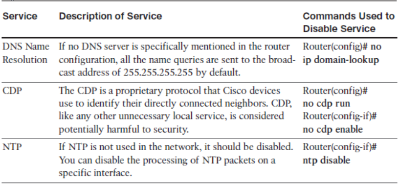
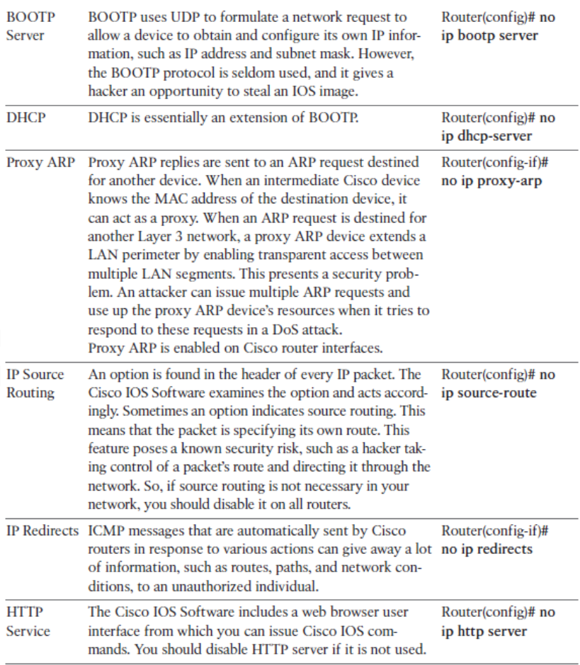
- Disable unneeded services
- Routers support many services.
- Some of these services are enabled for historical reasons, but are no longer required today.
- Services that are not needed on the router can be used as back doors to gain access to it and should therefore be disabled.
Router Security Policy
The router security policy should help answer the following questions regarding:
- Password encryption and complexity settings
- Authentication settings
- Management access settings
- Securing management access using SSH
- Unneeded services settings
- Ingress/egress filtering settings
- Routing protocol security settings
- Configuration maintenance
- Change management
- Router redundancy
- Monitoring and incident handling
- Security updates
- Password encryption and complexity settings: Do passwords appear in encrypted form when viewed at the configuration file? According to policy, how often do router passwords (Telnet, username, enable) have to be changed? Do the router passwords meet the required complexity as defined by the policy?
- Authentication settings: Is a message of the day (MOTD) banner defined? Is authentication on the router done through locally configured usernames and passwords, or through external AAA servers? Are login and logout tracking and command accounting for the router administrators through the external AAA server enabled?
- Management access settings: Is Telnet access allowed for router management? Is the HTTP or HTTPS server used for router management? Which version of SNMP is used to manage the router? Is the SNMP process restricted to a certain range of IP addresses only? How often is the SNMP community string changed?
- Securing management access using SSH: Is management access secure? Do we still have to support Telnet? Are we using SSH for management access? If Telnet support is required, how are we securing it?
- Unneeded services settings: Are the unneeded services and interfaces disabled? Which services are unneeded?
- Ingress/egress filtering settings: Is filtering of RFC 1918 IP addresses enabled? Are antispoofing ACLs in place? Is Unicast RPF filtering enabled?
- Routing protocol security settings: Is routing protocol message authentication enabled?
- Configuration maintenance: How often are the router configurations backed up? Is the backup moved to an offsite (disaster recovery) site? Is there a documented procedure for the backup of router configurations? Is TFTP used to transfer the configuration or the image files to and from the router? On the system where the configuration files are stored, is the local operating system’s security mechanism used for restricting the access to the files?
- Change management: Are all the router changes and the updates documented in a manner suitable for a review according to the change management procedure?
- Router redundancy: Do we have a first-hop redundancy protocol (FHRP) configured?
- Monitoring and incident handling: Are all the attempts to access any port, protocol, or service that is denied logged? Is the CPU utilization/memory of the router monitored? Is logging to a syslog server enabled on the router? What is the course of action to be followed if any malicious incident is noticed?
- Security updates: Is the network engineer aware of the latest vulnerabilities that could affect the router? Are the procedures
Use Strong Passwords
- Use a password length of ten or more characters. A longer password is a better password.
- Make passwords complex. Include a mix of uppercase and lowercase letters, numbers, symbols, and spaces.
- Avoid passwords based on repetition, dictionary words, letter or number sequences, usernames, relative or pet names, biographical information, such as birthdates, ID numbers, ancestor names, or other easily identifiable pieces of information.
- Deliberately misspell a password (for example, Smith = Smyth = 5mYth or Security = 5ecur1ty).
- Change passwords often. If a password is unknowingly compromised, the window of opportunity for the attacker to use the password is limited.
- Do not write passwords down and leave them in obvious places, such as on the desk or monitor.
- Use Strong Passwords
- Use a password length of ten or more characters. A longer password is a better password.
- Make passwords complex. Include a mix of uppercase and lowercase letters, numbers, symbols, and spaces.
- Avoid passwords based on repetition, dictionary words, letter or number sequences, usernames, relative or pet names, biographical information, such as birthdates, ID numbers, ancestor names, or other easily identifiable pieces of information.
- Deliberately misspell a password (for example, Smith = Smyth = 5mYth or Security = 5ecur1ty).
- Change passwords often. If a password is unknowingly compromised, the window of opportunity for the attacker to use the password is limited.
- Do not write passwords down and leave them in obvious places, such as on the desk or monitor.
Encrypting Passwords
- Encrypting Privileged EXEC Password
- enable secret password global configuration command. IOS 15.0(1)S and later default to the SHA256 hashing algorithm.
- Earlier IOS versions use the weaker message digest 5 (MD5) hashing algorithm.
- Encrypting Console and vty Passwords
- When defining a console or vty line password using the password line command, the passwords are stored in clear text in the configuration.
- To create local database entry encrypted to level 4 (SHA256), use the username name secret password global configuration command.
- The login local command makes the line authenticate using the credentials configured in the local database.
Authentication, Authorization, Accounting
Implementation of the AAA model provides the following advantages:
- Increased flexibility and control of access configuration
- Scalability
- Multiple backup systems
- Standardized authentication methods
Users must authenticate against an authentication database, which can be stored:
- Locally: created using the username secret command
- Centrally: A client/server model where users are authenticated against AAA servers.
Implementation of the AAA model provides the following advantages:
- Increased flexibility and control of access configuration: AAA offers additional authorization flexibility on a per-command or per-interface level.
- Scalability: Local authentication is appropriate for a small network with few administrative users. However, it does not scale well beyond that. AAA provides a very scalable solution that is required when managing large networks.
- Multiple backup systems: Multiple AAA servers can be identified for redundancy reasons. If a AAA server fails, the next server on the list would provide AAA services.
- Standardized authentication methods: AAA supports the RADIUS protocol open standard to ensure interoperability and flexibility with other vendor devices.
Users must authenticate against an authentication database, which can be stored:
- Locally: Users are authenticated against the local device database, which is created using the username secret command (sometimes referred to self-contained AAA).
- Centrally: A client/server model where users are authenticated against AAA servers. This provides improved scalability, manageability, and control. Communication between the device and AAA servers is secured using either the RADIUS or TACACS+ protocols.
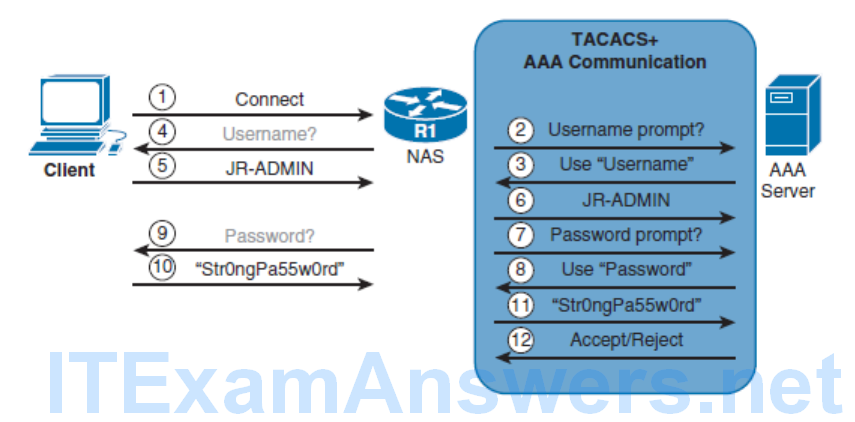
RADIUS and TACACS+ Overview
- RADIUS protocol
- An open standard protocol. It combines authentication and authorization into one service using UDP port 1812 (or UDP 1645), and the accounting service uses UDP port 1813 (or UDP 1646). RADIUS does not encrypt the entire message exchanged between device and server. Only the password portion of the RADIUS packet header is encrypted.
- TACACS+
- A Cisco proprietary protocol that separates all three AAA services using the more reliable TCP port 49. TACACS+ encrypts the entire message exchanged therefore communication between the device and the TACACS+ server is completely secure.
RADIUS Message Exchange

TACACS+ Message Exchange
Enabling AAA and Local Authentication
The following are the configuration steps required to enable AAA local authentication:
- Step 1. Create local user accounts using the username name secret password global configuration command.
- Step 2. Enable AAA by using the aaa new-model global configuration command.
- Step 3. Configure the security protocol parameters including the server IP address and secret key
- Step 4. Define the authentication method lists using the aaa authentication login {default | list-name } method1 […[ method4 ]].
- Step 5. If required, apply the method lists to the console, vty, or aux lines.
- Step 6. (Optional) Configure authorization using the aaa authorization global configuration command.
- Step 7. (Optional) Configure accounting using the aaa accounting global configuration command.
- Step 1. Create local user accounts using the username name secret password global configuration command.
- Step 2. Enable AAA by using the aaa new-model global configuration command.
- This command is required to enable all other AAA-related commands. Until this command is enabled, all other AAA commands are hidden. The command also immediately applies local authentication to all lines and interfaces except the console line.
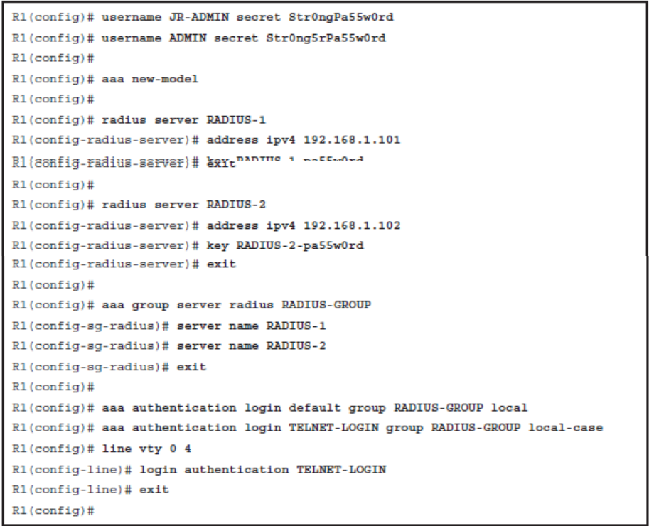
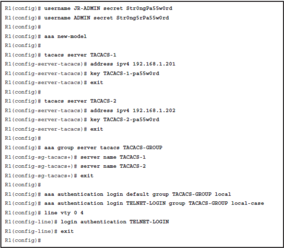
- Step 3. Configure the security protocol parameters including the server IP address and secret key. The actual commands will vary depending on whether RADIUS or TACACS+ is used and whether multiple servers are being implemented.
- Step 4. Define the authentication method lists using the aaa authentication login {default | list-name } method1 […[ method4 ]]. The default method list applies to any interface, line, or service unless a list-name method list is defined. The default keyword is typically used in smaller environments with a single shared AAA infrastructure. Alternatively, a list-name method list must be explicitly applied to an interface, line, or service. The list-name method list overrides the default method list. Multiple authentication methods can be defined for fault tolerance. The most commonly used aaa authentication command methods include group radius , group tacacs+ , local , local-case . When multiple authentication methods are configured, the additional methods of authentication are used only if the previous method returns an error, not if it fails.
- Step 5. If required, apply the method lists to the console, vty, or aux lines. If a default authentication method was defined, the console, vty, and aux lines are automatically configured for AAA authentication. If a list-name was configured, the lines require the login list-name line configuration command.
- Step 6. (Optional) Configure authorization using the aaa authorization global configuration command.
- Step 7. (Optional) Configure accounting using the aaa accounting global configuration command.
Configure RADIUS Authentication with Local User for Fallback
Configure TACACS+ Authentication with Local User for Fallback
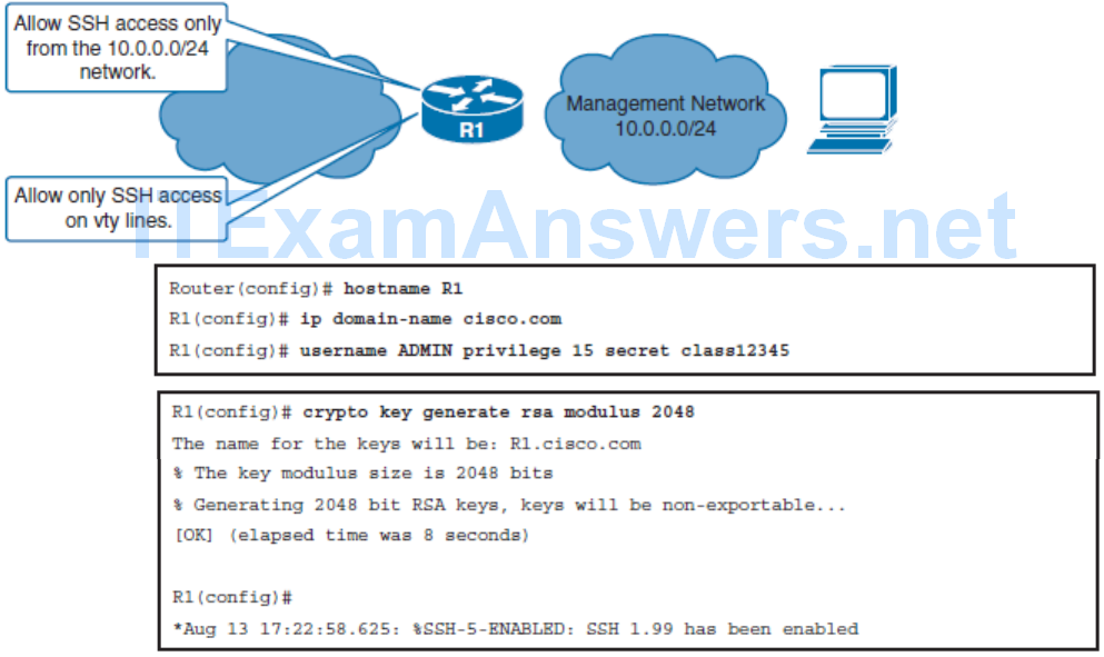
Use SSH Instead of Telnet
Complete the following steps to enable the SSH access instead of Telnet:
- Step 1. Enable the use of SSH protocol: Ensure that the target routers are running a Cisco IOS release that supports SSH.
- Step 2. Enable local authentication for SSH access: This is because SSH access requires login using username and password.
- Step 3. Enable the use of SSH protocol: Optionally allow SSH access only from authorized hosts by specifying an ACL.
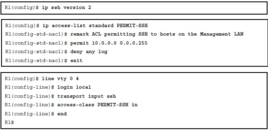
- Cisco routers support two versions of SSH:
- SSH Version 1 (SSHv1): Original version but has known vulnerabilities
- SSH Version 2 (SSHv2): Provides better security using the Diffie-Hellman key exchange and the strong integrity-checking message authentication code (MAC)
Securing Access to the Infrastructure Using Router ACLs
All the traffic to the IP addresses of the network infrastructure devices is dropped and logged.
- This rule prevents the network users from sending the routing protocol or the management traffic to network devices.
- Include the destination addresses that encompass all the device IP addresses as a condition.
All the other traffic is permitted and allows all the transit traffic over the network.
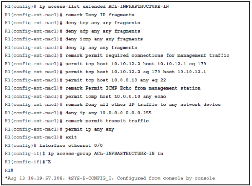
- The ACL denies IP fragments. Fragmentation is often used in attempts to evade detection by intrusion detection systems. It is for these reasons that IP fragments are often used in attacks, and why they must be explicitly filtered at the top of any configured infrastructure ACLs.
- The ACL permits BGP sessions from trusted hosts to local IP addresses, and allows the SSH management traffic from a trusted management station. Similar entries should also be configured to allow internal routing protocols if any are used inside the network.
- The ACL also permits ICMP echo (ping) traffic from the trusted management station.
- The ACL then denies all the other traffic to the infrastructure IP addresses.
- The ACL finally permits all the transit traffic across the router.
Implement Unicast Reverse Path Forwarding
- Unicast Reverse Path Forwarding (uRPF) helps limit the malicious traffic on an enterprise network.
- This security feature works with Cisco Express Forwarding (CEF) by enabling the router to verify that the source of any IP packets received is in the CEF table and reachable via the routing table. If the source IP address is not valid, the packet is discarded.
- Prevents common spoofing attacks and follows RFC 2827 for ingress filtering to defeat denial-of-service (DoS) attacks, which employ IP source address spoofing.
- RFC 2827 recommends that service providers filter their customers’ traffic and drop any traffic entering their networks that is coming from an illegitimate source address.
The uRPF feature works in one of two modes:
Strict mode
- The packet must be received on the interface that the router would use to forward the return packet.
- uRPF configured in strict mode may drop legitimate traffic that is received on an interface that was not the router’s choice for sending return traffic.
- Dropping this legitimate traffic could occur when asymmetric routing paths are present in the network.
- Use the ip verify unicast source reachable-via rx command.
Loose mode
- The source address must appear in the routing table.
- Administrators can change this behavior using the allow-default option, which allows the use of the default route in the source verification process.
- In addition, a packet that contains a source address for which the return route points to the Null 0 interface will be dropped.
- An access list may also be specified that permits or denies certain source addresses in uRPF loose mode.
- Use the ip verify unicast source reachable-via any command
The allow-default option may be used with either the rx or any option to include IP addresses not specifically contained in the routing table. The allow-self-ping option should not be used because it could create a DoS condition. A numbered access list can also be configured to specifically permit or deny a list of addresses through uRPF.
Enabling uRPF

Implement Logging
- Network administrators need to implement logging to get insight into what is happening in their network.
- Although logging can be implemented locally on a router, this method is not scalable.
- Therefore, it is important to implement logging to external destination.

- These logs and reports can include content flow, configuration changes, and new software installs, to name a few. Logging helps to detect unusual network traffic, network device failures, or just to monitor what kind of traffic traverses the network.
- As well, if a router reloads then all the logs stored on it will be lost.
- Network Time Protocol (NTP) can be used to synchronize network devices to the correct time.
- It is also important that syslog entries be stamped with the correct time and date.
- Time stamps are configured using the service timestamps [ debug | log ] [ uptime | datetime [ msec ]] [localtime ] [ show-timezone ] [ year ] global configuration command.
Implementing Network Time Protocol
- An NTP network usually gets its time from an authoritative time source, such as a radio clock or an atomic clock attached to a time server.
- NTP then distributes this time across the network using UDP port 123.
NTP Modes
- Server: Also called the NTP master because it provides accurate time information to clients. Configured with the ntp master [ stratum ] global configuration command.
- Client: Synchronizes its time with the NTP server. An NTP client is enabled with the ntp server { ntp-master-hostname | ntp-master-ip-address } command.
- Peers: Also called symmetric mode, peers exchange time synchronization information. Peers are configured using the ntp peer { ntp-peerhostname | ntp-peer-ip-address } command.
- Broadcast/multicast: Special “push” mode of NTP server that provides one-way time announcements to receptive NTP clients. Typically used when time accuracy is not a big concern. Configured with the ntp broadcast client interface configuration command.
- Peers: Also called symmetric mode, peers exchange time synchronization information. Symmetric modes are most often used between two or more servers operating as a mutually redundant group. Peers are configured using the ntp peer { ntp-peerhostname | ntp-peer-ip-address } command.
Enabling NTP
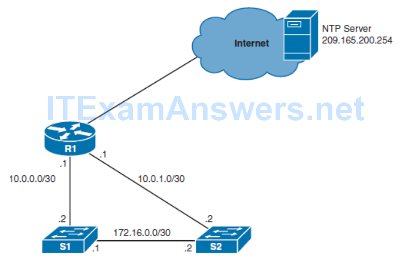
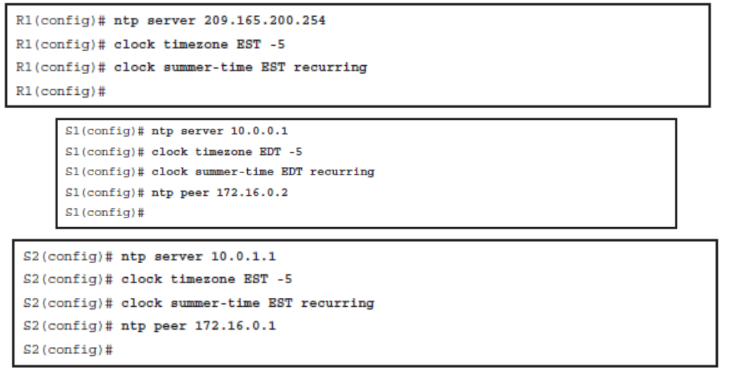
Note NTP is slow to synchronize and can take up to 5 minutes for a device to synchronize with an upstream server.
S1 is also configured to adjust the time and to identify S2 as its NTP peer. NTP peers exchange time information with each other and help prevent a single point of failure.
Securing NTP
- Authentication
- NTP authenticates the source of the information, so it only benefits the NTP client. Cisco devices support only MD5 authentication for NTP.
- Access control lists
- Configure access lists on devices that provide time synchronization to others. ACLs are applied to NTP using the ntp access-group { peer | query-only | serve | serve-only }
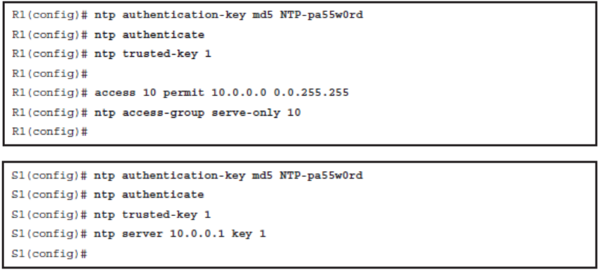
NTP Authentication Configuration
- Step 1
- Define NTP authentication key or keys with the ntp authentication-key key_number md5 pass global configuration command. Every number specifies a unique NTP key.
- Step 2
- Enable NTP authentication using the ntp authenticate global configuration command.
- Step 3
- Tell the device which keys are valid for NTP authentication using the ntp trusted-key key global configuration command. The key argument should be the key defined in Step 1.
- Step 4
- Specify the NTP server that requires authentication using the ntp server ip_address key key_number global configuration command. The command can also be used to secure NTP peers.
NTP Authentication

NTP Versions
Currently NTP Versions 3 and 4 are used in production networks. NTPv4 is an extension of NTP Version 3 and provides the following capabilities:
- Supports both IPv4 and IPv6 and is backward-compatible with NTPv3. NTPv3 does not support IPv6.
- Uses IPv6 multicast messages instead of IPv4 broadcast messages to send and receive clock updates.
- Improved security over NTPv3 as NTPv4 provides a whole security framework based on public key cryptography and standard X509 certificates.
- Improved time synchronization and efficiency.
- NTPv4 access group functionality accepts IPv6 named access lists as well as IPv4 numbered access lists.
- Improved time synchronization and efficiency as NTPv4 can automatically discover the hierarchy of NTP servers to achieve the best time accuracy for the lowest bandwidth cost. It does so by using multicast groups to automatically calculate the timedistribution hierarchy through an entire network.
Implementing SNMP
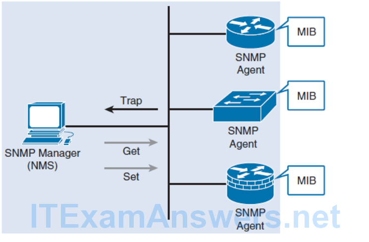
Note A Get action provides the SNMP manager with read access to the SNMP agent’s Management Information Base (MIB), and a Set action provides read-write access to the SNMP device.
SNMP defines management information between these three elements:
- SNMP manager
- The SNMP manager collects information from an SNMP agent using the Get action and can change configurations on an agent using the Set action.
- SNMP agents (managed node)
- Resides on the SNMP-managed networking client and responds to the SNMP manager’s Set and Get requests to the local MIB.
- SNMP agents can be configured to forward real-time information directly to an SNMP´manager using traps (or notifications).
- Management Information Base (MIB)
- Resides on the SNMP-managed networking client and stores data about the device operation including resources and activity. The MIB data is available to authenticated SNMP managers.
SNMP Versions
- SNMPv1
- Original version, which uses community strings for authentication. These community strings are exchanged in clear text and therefore very unsecure. SNMPv1 is considered to be obsolete.
- SNMPv2
- Update to SNMPv1 that improved performance, security, confidentiality, and SNMP communications. SNMPv2c is the standard and uses the same community string authentication format of SNMPv1.
- SNMPv3
- Update to SNMPv2 that adds security and remote configuration enhancements. Specifically, SNMPv3 provides authentication, message integrity, and encryption.
- noAuthNoPriv: Authenticates SNMP messages using a clear-text community string
- authNoPriv: Authenticates SNMP messages using either HMAC with MD5 or HMAC with SHA-1
- authPriv: Authenticates SNMP messages by using either HMAC-MD5 or SHA usernames and encrypts SNMP messages using DES, 3DES, or AES
Differences Between SNMP Security Levels

SNMP Protection
- There are two types of community strings in SNMPv2:
- Read-only (RO): Provides access to the MIB variables, but does not allow these variables to be changed, only read. Because security is so weak in SNMPv2, many organizations only use SNMP in this read-only mode.
- Read-write (RW): Provides read and write access to all objects in the MIB.
If SNMPv2 is used, it should be secured by
- Using an uncommon, complex, long community string.
- Changing the community strings at regular intervals.
- Enabling read-only access only. If read write access is required, limit the read write access to the authorized SNMP manager.
- SNMP trap community names must be different than Get and Set community strings.
Sample SNMPv2 Configuration

Configuring SNMPv3
- Step 1. Configure an ACL to limit who has access SNMP access to the device.
- Step 2. Configure an SNMPv3 view using the snmp-server view view-name global configuration command.
- Step 3. Configure an SNMPv3 group using the snmp-server group group-name global configuration command.
- Step 4. Configure an SNMPv3 user using the snmp-server user username groupname global configuration command.
- Step 5. Configure an SNMPv3 trap receiver using the snmp-server host global configuration command.
- Step 6. Configure interface index persistence using the snmp-server ifindex persist global configuration command.
Sample SNMPv3 Configuration
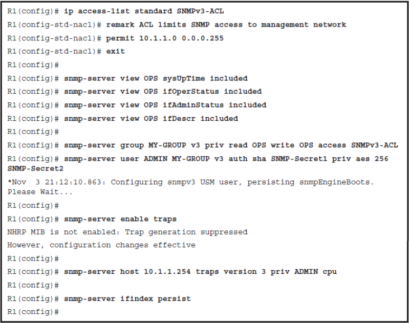
- In the example, the SNMPv3-ACL is created and will be used to limit SNMP access to the local device to users in the management subnet (that is, 10.1.1.0/24).
- Next a view called OPS is created that will be used as both read and write view for the group MY-GROUP. Specific MIB object IDs (OIDs) can be included or excluded from the view. In the example, the OIDs for system uptime, interface status, and description were added.
- The security policy binding users and groups is configured next. The SNMPv3 group MY-GROUP is configured with authPriv security level ( snmp-server group MY-GROUP v3 priv ) and the user ADMIN ( snmp-server ADMIN MY-GROUP ) with passwords for both authentication ( auth sha SNMP-Secret1 ) and encryption ( priv aes 256 SNMPSecret2 ).
- SNMP traps are then enabled with the snmp-server enable traps command. SNMPv3 traps will be sent by R1 to the 10.1.1.254 IP address ( snmp-server host 10.1.1.254 traps ) using authPriv security level ( priv ) for the user ADMIN.
- Events for which traps are sent can also be limited, and in the example, only CPU-related events ( cpu ) will be sent. SNMP identifies object instances, such as network interfaces, by their numeric indexes.
- This may cause problems when the number of instances changes. For example, if a new loopback interface is configured, index numbers would shuffle. As a consequence, NMS may mismatch data from different interfaces. To prevent index shuffle, the snmp-server ifindex persist command should be used to guarantee index persistence over device reboots and minor software upgrades.
Verifying SNMPv3
- show snmp
- Provides basic information about the SNMP configuration.
- Displays SNMP traffic statistics, see whether the SNMP agent is enabled, or verify whether the device is configured to send traps, and if so, to which SNMP managers.
- show snmp view
- Provides information about configured SNMP views to verify for each group, see which OIDs are included
- show snmp group
- Provides information about the configured SNMP groups. The most important parameters are the security model and levels.
Configuration Backups

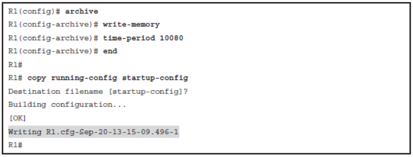
The archive Command is used to perform backups automatically.
- The path is a required parameter that is specified by using URL notation form. It can denote either a local or a network path.
- You can use two variables with the path command:
- $h will be replaced with device hostname.
- $t will be replaced with date and time of the archive.
Archive Configuration
Manually

Automatically
Verifying Archives

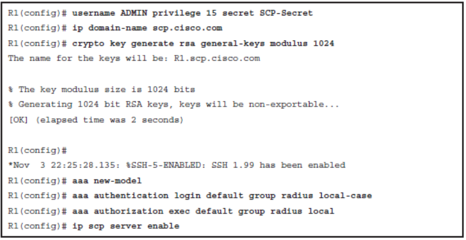
Using SCP
- The Secure Copy (SCP) feature provides a secure and authenticated method for copying router configuration or router image files.
Enabling SCP on a Router
- Step 1. Use the username name [ privilege level ] { secret password } command for local authentication or configure TACACS+ or RADIUS.
- Step 2. Enable SSH. Configure a domain name using the ip domain-name and generating the crypto keys using the crypto key generate rsa general key global configuration commands.
- Step 3. AAA with the aaa new-model global configuration mode command.
- Step 4. Use the aaa authentication login { default | list-name } method1 [ method2 …] command to define a named list of authentication methods.
- Step 5. Use the aaa authorization { network | exec | commands level } { default | listname } method1… [ method4 ] command to configure command authorization.
- Step 6. Enable SCP server-side functionality with the ip scp server enable command.
Sample SCP Configuration
Disabling Unused Services
Conditional Debugging
It is practical to know how to limit debug output:
- Use an ACL
- Enable conditional debugging
The debug ip packet [ access-list ] command displays general IP debugging and is useful for analyzing messages traveling between local and remote hosts and to narrow down the scope of debugging.
Conditional debugging is sometimes called “conditionally triggered debugging.” It can be used to
- Limit output based on the interface. Debugging output is turned off for all interfaces except the specified interface.
- Enable debugging output for conditional debugging events. Messages are displayed as different interfaces meet specific conditions.
To enable, define the condition with the debug condition interface
Enabling Conditional Debugging
Commands required to debug NAT and IP packet details and limit to output for interface Fa0/0 only.

Routing Protocol Authentication Options
- The purpose of routing protocol authentication
- Increasing the security of routing protocol authentication with time-based key chains
- Authentication options with different routing protocols
The Purpose of Routing Protocol Authentication
The falsification of routing information is a more subtle class of attack that targets the information carried within the routing protocol.
The consequences of falsifying routing information are as follows:
- Redirect traffic to create routing loops
- Redirect traffic to monitor on an insecure line
- Redirect traffic to discard it
Two types of neighbor authentication can be used:
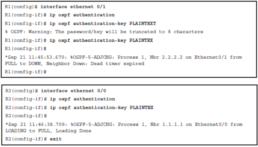
- Plain-text authentication
- Hashing authentication
Plain-Text Authentication

Hashing Authentication
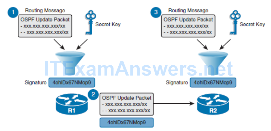
- The process can be explained in three steps:
- Step 1. When R1 sends a routing update to R2, it uses a hashing algorithm such as MD5 or SHA. The hashing algorithm is essentially a complex mathematical formula that uses the data in the OSPF update and a predefined secret key to generate a unique hash value (signature). The resulting signature can be derived only by using the OSPF update and the secret key that is only known to the sender and receiver.
- Step 2. The resulting signature is appended to the routing update and sent to R2.
- Step 3. When R2 receives the routing update and uses the same hashing algorithm as R1 to calculate a hash value. Specifically, it uses the data from the received OSPF update and its predefined secret key.
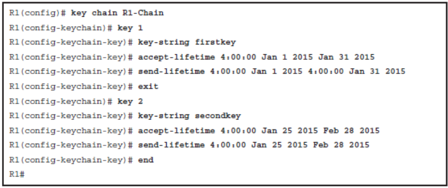
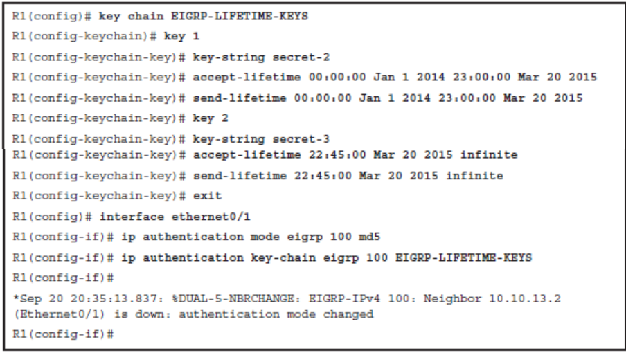
Time-Based Key Chains
Key Chain Specifics:
- Key ID: Configured using the key key-id key chain configuration mode command. Key IDs can range from 1 to 255.
- Key string (password): Configured using the key-string password key chain key configuration mode command.
- Key lifetimes: (Optional) Configured using the send-lifetime and accept-lifetime key chain key configuration mode commands.
Sample EIGRP Key Chain Configuration
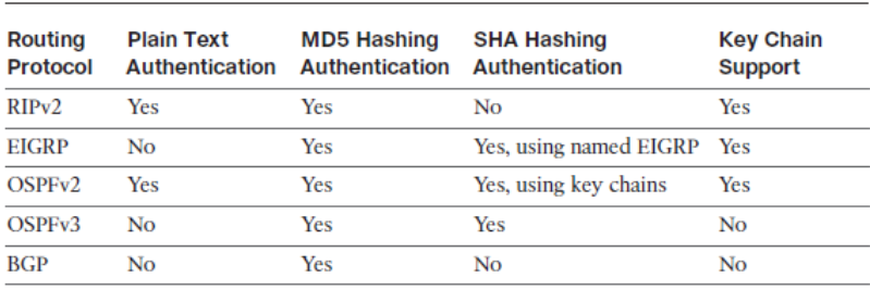
Authentication Options with Different Routing Protocols
Configuring EIGRP Authentication
This section describes how to configure the following:
- Classic IPv4 and neighbor authentication using preshared passwords
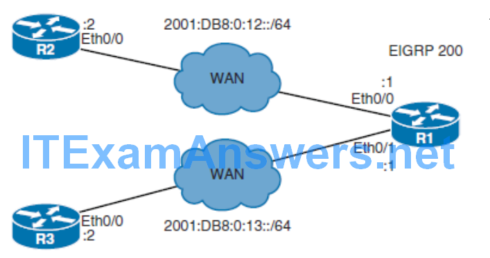
- IPv6 EIGRP neighbor authentication using preshared passwords
- Classic IPv4 and IPv6 EIGRP neighbor authentication using the named EIGRP method
EIGRP Authentication Configuration Checklist
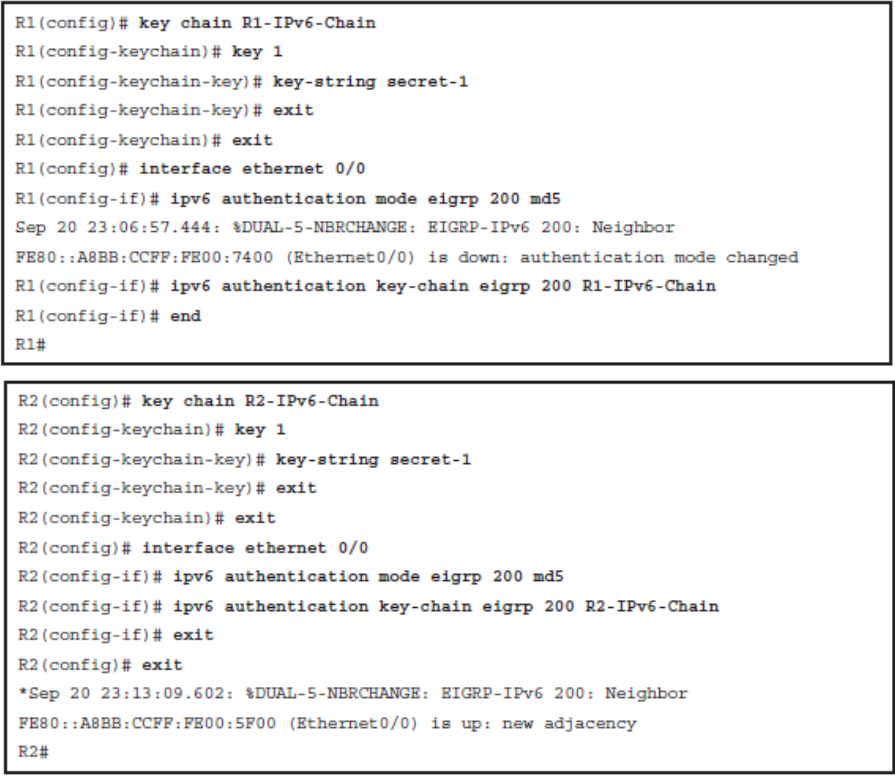
- Step 1. Configure the key chain
- The key chain global configuration command is used to define all the keys that are used for EIGRP MD5 authentication.
- Once in key chain configuration mode, use the key command to identify the key in the key chain.
- When the key command is used, the configuration enters the key chain key configuration mode, where the key-string authentication-key configuration command must be used to specify the authentication string (or password).
- The key ID and authentication string must be the same on all neighboring routers.
- Step 2. Configure the authentication mode for EIGRP
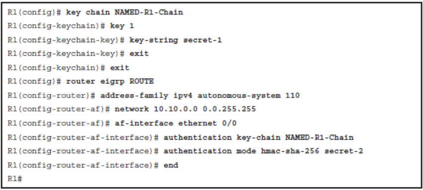
- The only authentication type that is available in classic EIGRP configuration is MD5. The newer named EIGRP configuration method also supports the more secure SHA hashing algorithm.
- Step 3. Enable authentication to use the key or keys in the key chain
- Authentication is enabled using the ip authentication key-chain eigrp interface command.
Configuring EIGRP Authentication
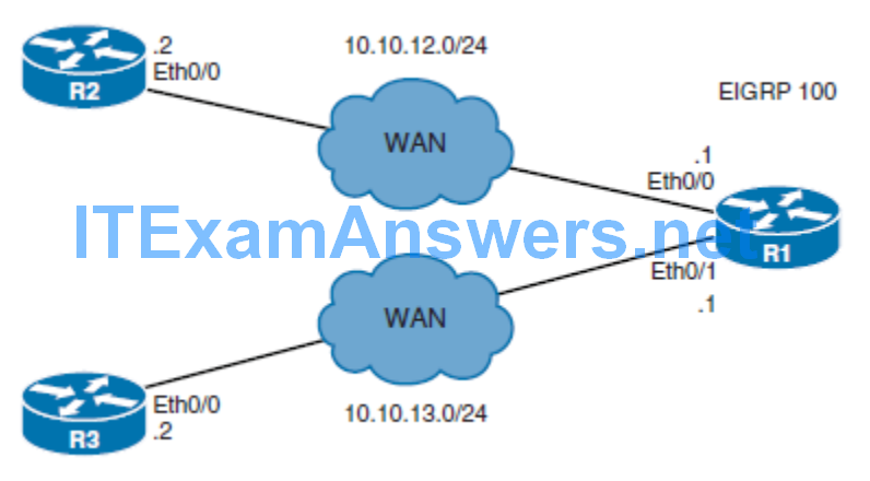
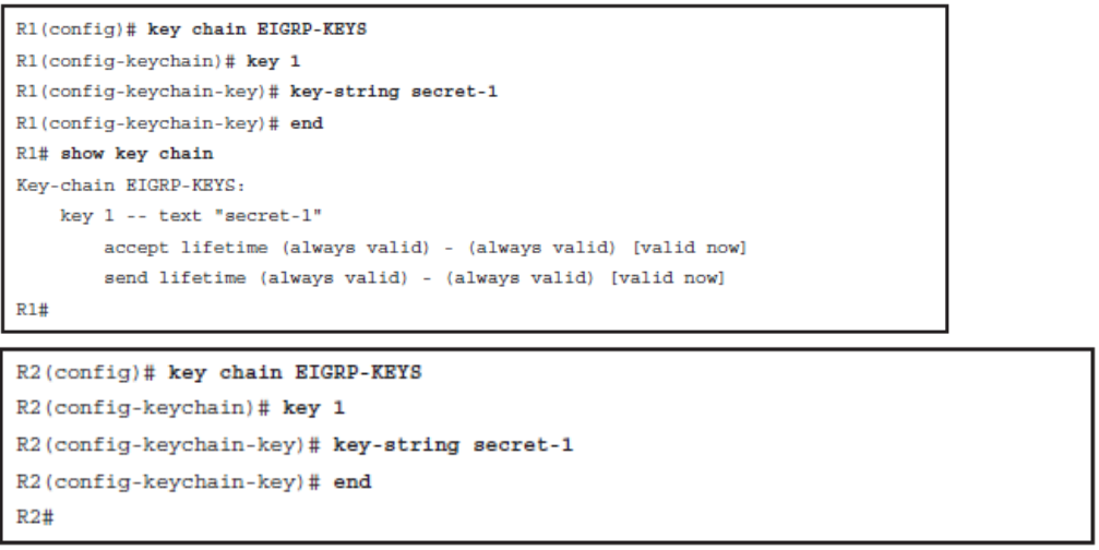
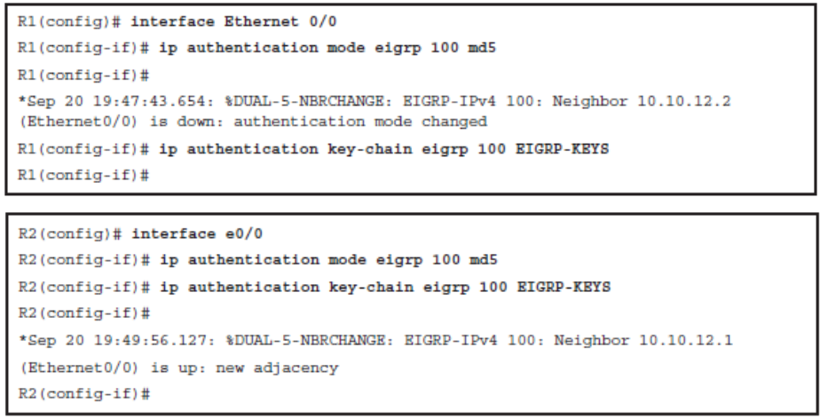
Configure EIGRP Key-Based Routing Authentication
Configuring EIGRP for IPv6 Authentication
Configuring Named EIGRP Authentication
Configuring OSPF Authentication
This section describes how to do the following:
- Configure OSPFv2 neighbor authentication
- Configure OSPFv3 neighbor authentication
OSPF Authentication
- By default, OSPF does not authenticate routing updates. This means that routing exchanges over a network are not authenticated. OSPFv2 supports
- Plain-text authentication
- Simple password authentication. Least secure and not recommended for production environments.
- MD5 authentication
- Secure and simple to configure using two commands. Should only be implemented if SHA authentication is not supported.
- SHA authentication
- Most secure solution using key chains. Referred to as the OSPFv2 cryptographic authentication feature and only available since IOS 15.4(1)T.
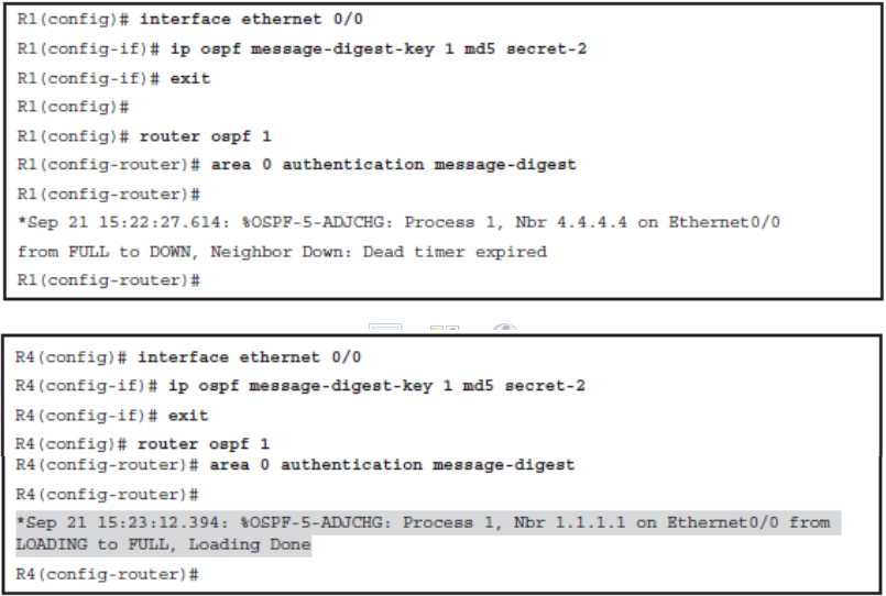
OSPF MD5 Authentication
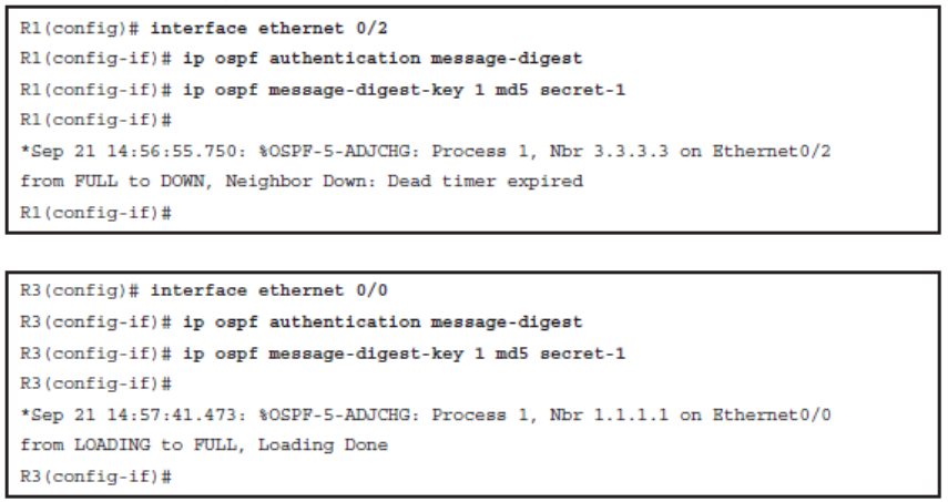
There are two tasks to enable MD5 hashing authentication:
- Step 1.
- Configure a key ID and keyword (password) using the ip ospf message-digest key key-id md5 password interface configuration command. The key ID and password are used to generate the hash value that is appended to the OSPF update. The password maximum length is 16 characters. Cisco IOS Software will display a warning if a password longer than 16 characters is entered.
- Step 2
- Enable MD5 authentication using either the ip ospf authentication message-digest interface configuration command or the area area-id authentication message-digest OSPF router configuration command. The first command only enables MD5 authentication on a specific interface, and the second command enables authentication for all OSPFv2 interfaces within an area.
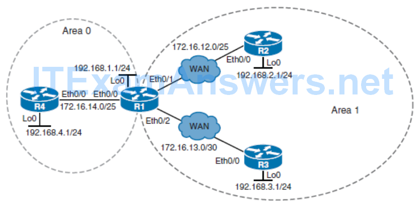
Configure OSPF MD5 Authentication
Configure OSPF MD5 Authentication – Interface
Configure OSPF MD5 Authentication in an Area
OSPFv2 Cryptographic Authentication
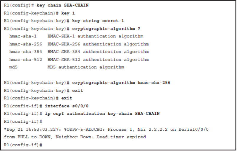
- Step 1.
- Configure a key chain using the key chain key-name global configuration command. The key chain contains the key ID and key string and enables the cryptographic authentication feature using the cryptographic-algorithm auth-algo key chain key configuration mode command.
- Step 2.
- Assign the key chain to the interface using the ip ospf authentication keychain key-name interface configuration mode command. This also enables the feature.
Configure OSPFv2 Cryptographic Authentication Example
OSPFv3 Authentication
- OSPFv3 requires the use of IPsec to enable authentication.
- In OSPFv3, authentication fields have been removed from OSPFv3 packet headers.
- When OSPFv3 runs on IPv6, OSPFv3 requires the IPv6 Authentication Header (AH) or IPv6 Encapsulating Security Payload (ESP) header to ensure integrity, authentication, and confidentiality of routing exchanges.
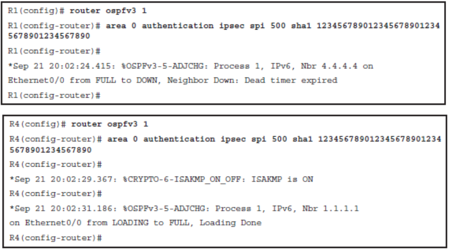
- To deploy OSPFv3 authentication, first define the security policy on each of the devices within the group. The security policy consists of the combination of the key and the security parameter index (SPI). The SPI is an identification tag added to the IPsec header.
Configuring OSPFv3 Authentication
- The authentication policy can be configured either on an
- Interface
- Can be configured using either the ospfv3 authentication { ipsec spi } { md5 | sha1 } { key-encryption-type key } | null interface configuration command or the ipv6 ospf authentication { null | ipsec spi spi authentication-algorithm [ keyencryption- type ] [ key ]} interface configuration commands. A key with the key length of exactly 40 hex characters must be specified.
- Area
- Use the area area-id authentication ipsec spi spi authentication-algorithm [ key-encryption-type ] key router configuration mode. When configured for an area, the security policy is applied to all the interfaces in the area. For higher security, use a different policy on each interface.
Configuring OSPFv3 Authentication on an Interface Example
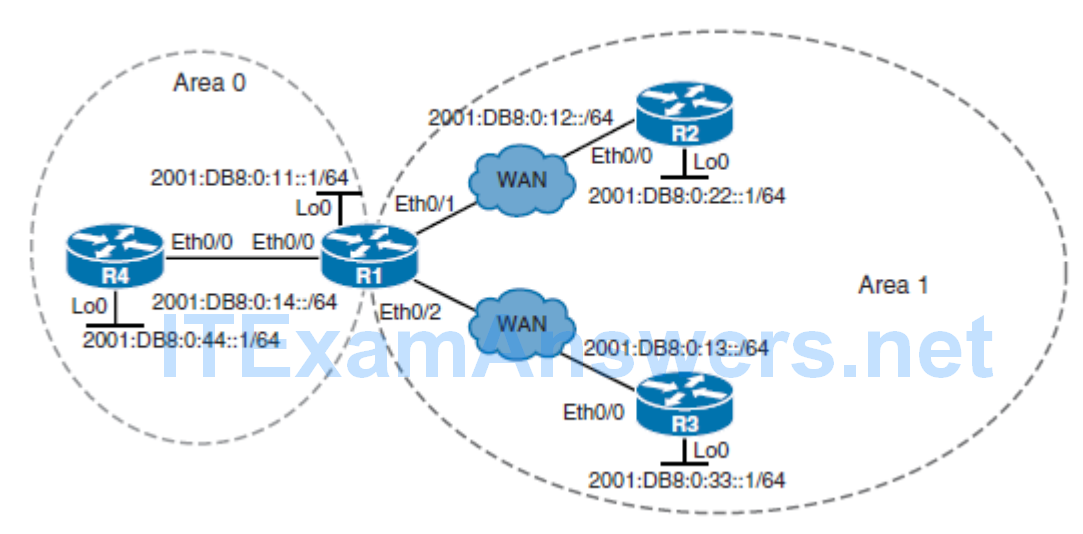
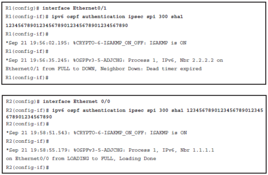
- Notice the key argument in the ipv6 ospf authentication command must be exactly 40 hexadecimal digits.
Configuring OSPFv3 Authentication for Area 0
Configuring BGP Authentication
This section covers the following topics:
- How BGP authentication using MD5 hashes works
- Configuring and verifying BGP for IPv4 authentication
- Configuring and verifying BGP for IPv6 authentication
BGP Authentication Configuration Checklist
- BGP neighbor authentication can be configured on a router so that the router authenticates the source of each routing update packet that it receives. This authentication is accomplished by the exchange of an authentication key.
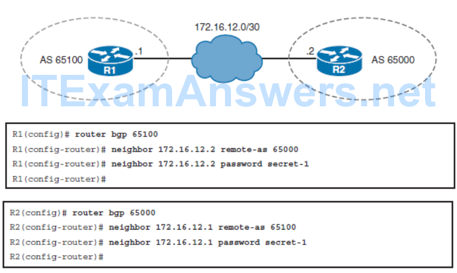
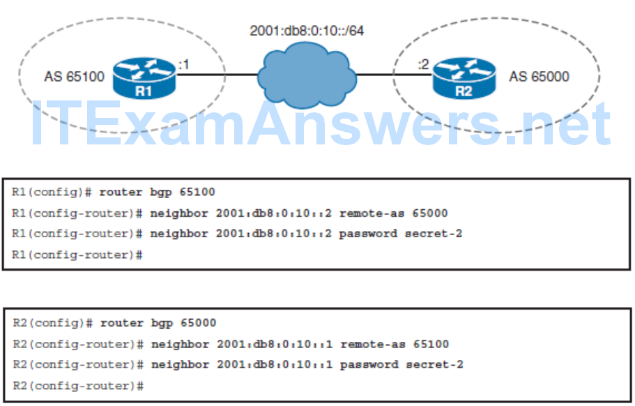
- Like EIGRP and OSPF, BGP also supports MD5 neighbor authentication. To generate an MD5 hash value, BGP uses the shared secret key and portions of the IP and TCP headers and the TCP payload.
- The MD5 hash is then stored in TCP option 19, which is created specifically for this purpose by RFC 2385.
- Successful MD5 authentication requires the same password on both BGP peers.
- Configuring MD5 authentication causes Cisco IOS Software to generate and check the MD5 digest of every segment that is sent on the TCP connection.
BGP Authentication Configuration
BGP for IPv6 Authentication Configuration
Implementing VRF-Lite
- Virtual Routing and Forwarding (VRF) is a technology that allows the device to have
- multiple but separate instances of routing tables exist and work simultaneously.
- A VRF instance is essentially a logical router and consists of an IP routing table, a forwarding table, a set of interfaces that use the forwarding table, and a set of rules and routing protocols that determine what goes into the forwarding table.
- A VRF increases
- Network functionality by allowing network paths to be completely segmented without using multiple devices.
- Network security because traffic is automatically segmented. VRF is conceptually similar to creating Layer 2 VLANs but operates at Layer 3.
- Service providers (SPs) often take advantage of VRF to create separate virtual private networks (VPNs) for customers. Therefore, VRF is often referred to as VPN routing and forwarding .
VRF and VRF-Lite
- VRF is usually associated with a service provider running Multiprotocol Label Switching (MPLS) because the two work well together. In a provider network, MPLS isolates each customer’s network traffic, and a VRF is maintained for each customer.
- However, VRF can be used in other deployments without using MPLS.
- VRF-lite is the deployment of VRF without MPLS. With the VRF-lite feature, the Catalyst switch supports multiple VPN routing/forwarding instances in customer-edge devices.
- VRF-lite allows an SP to support two or more VPNs with overlapping IP addresses using one interface. VRF-lite uses input interfaces to distinguish routes for different VPNs and forms virtual packet-forwarding tables by associating one or more Layer 3 interfaces with each VRF.
- Interfaces in a VRF can be either physical, such as Ethernet or serial ports, or logical, such as VLAN SVIs. However, a Layer 3 interface cannot belong to more than one VRF at any time.
Enabling VRF
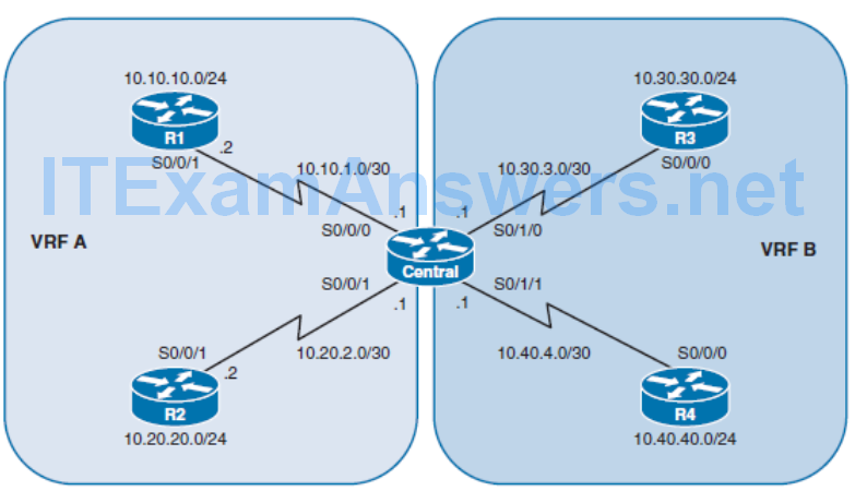
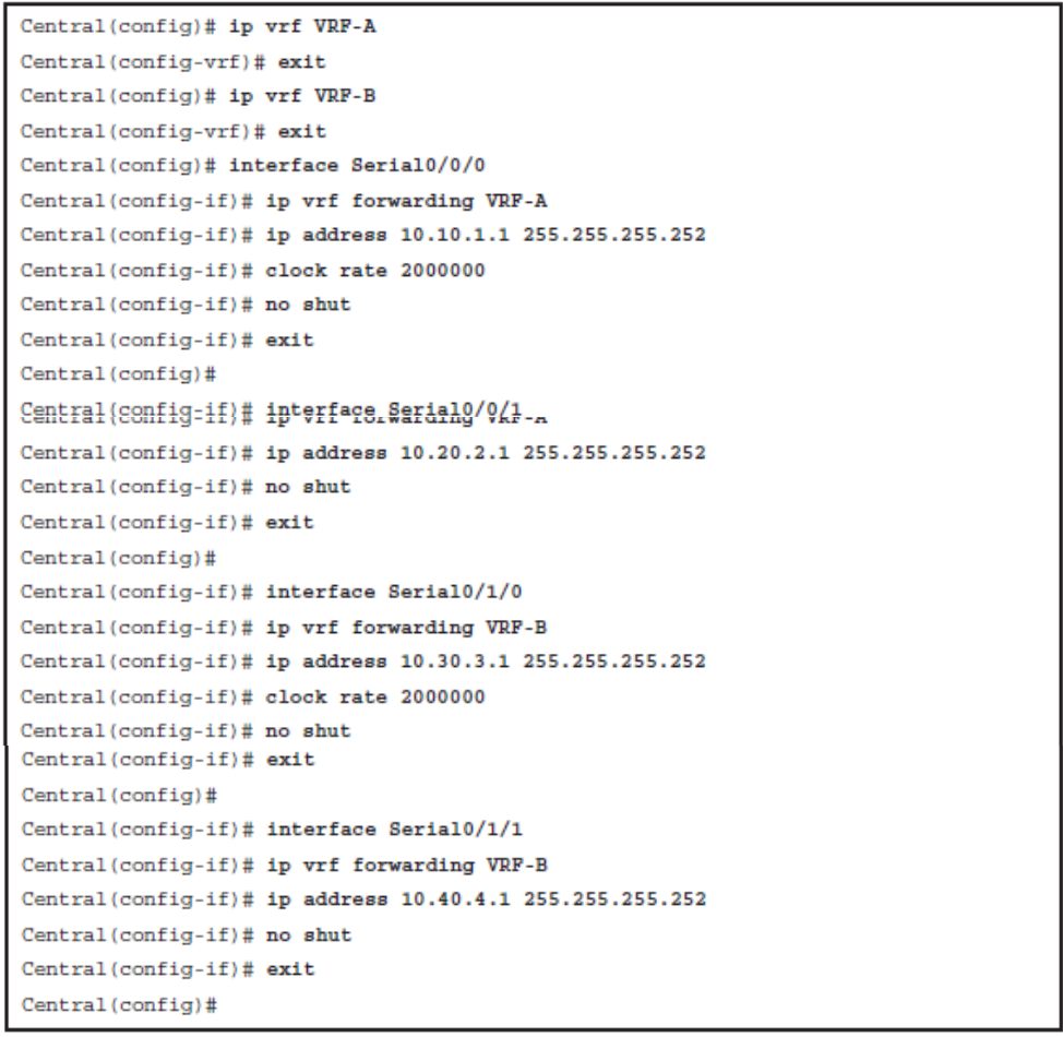
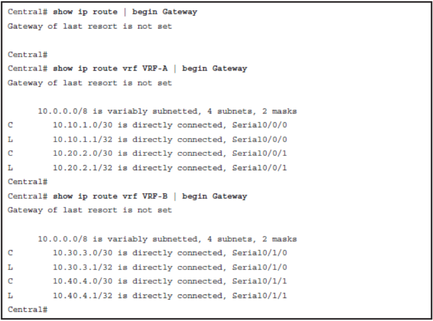
Verify the Routing Table in VRF Environment
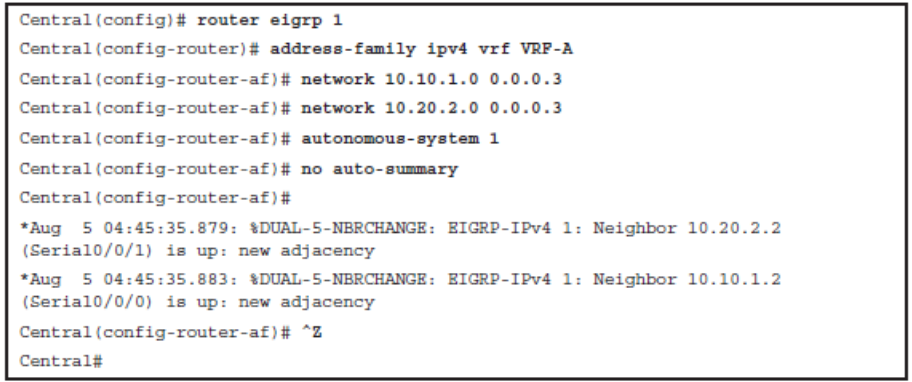
Enable EIGRP for VRF-A
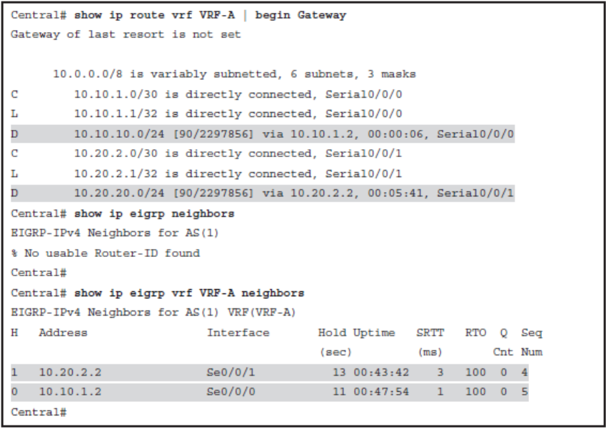
Verify the Routing Table of VRF-A
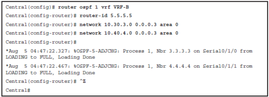
Enable OSPF for VRF-B
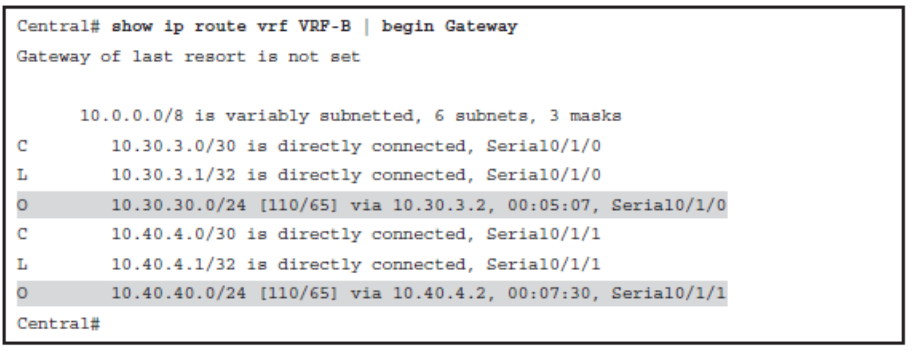
Verify the Routing Table of VRF-B
Easy Virtual Network
- For true path isolation, Cisco Easy Virtual Network (EVN) provides the simplicity of Layer 2 with the controls of Layer 3.
- EVN provides traffic separation and path isolation capabilities on a shared network infrastructure.
- EVN is an IP-based network virtualization solution that takes advantage of existing VRFlite technology to:
- Simplify Layer 3 network virtualization
- Improve support for shared services
- Enhance management and troubleshooting
- EVN reduces network virtualization configuration significantly across the entire network infrastructure by creating a virtual network trunk. The traditional VRF-lite solution requires creating one subinterface per VRF on all switches and routers involved in the data path, creating a lot of burden in configuration management.
- EVN removes the need of per-VRF subinterface by using the vnet trunk interface command.

Chapter 8 Summary
- Write and follow a security policy before securing a device.
- Passwords are stored in the configuration and should be protected from eavesdropping.
- Use SSH instead of Telnet, especially when using it over an unsecure network.
- Create router ALCs to protect the infrastructure by filtering traffic on the network edge.
- Secure SNMP if it is used on the network.
- Periodically save the configuration in case it gets corrupted or changed.
- Implement logging to an external destination to have insight into what is going on in a network.
- Disable unused services.
- Unauthorized routers might launch a fictitious routing update to convince a router to send traffic to an incorrect destination. Routers authenticate the source of each routing update that is received when routing authentication is enabled.
- There are two types of routing authentication: plain-text and hashing authentication.
- Avoid using plain-text authentication.
- A key chain is a set of keys that can be used with routing protocol authentications.
- Different routing protocols support different authentication options.
- When EIGRP authentication is configured, the router verifies every EIGRP packet.
- Classic EIGRP for IPv4 and IPv6 supports MD5 authentication, and named EIGRP supports SHA authentication.
- To configure classic MD5 authentication, define a key, enable EIGRP authentication mode on the interface, and associate the configured key with the interface.
- To configure SHA authentication, you need to use EIGRP named configuration mode.
- Verify the EIGRP authentication by verifying neighborship.
- When authentication is configured, the router generates and checks every OSPF packet and authenticates the source of each update packet that it receives.
- In OSPFv2 simple password authentication the routers send the key that is embedded in the OSPF packets.
- In OSPFv2 MD5 authentication the routers generate a hash of the key, key ID, and message. The message digest is sent with the packet.
- OSPFv3 uses native functionality offered by IPv6. All that is required for OSPFv3 authentication is IPsec AH. AH provides authentication and integrity check. Ipsec ESP provides encryption for payloads, which is not required for authentication.
- BGP authentication uses MD5 authentication.
- Router generates and verifies MD5 digest of every segment sent over the BGP connection.
- Verify BGP authentication by verifying if BGP sessions are up.
