Objectives
- Basic OSPF Configuration and OSPF Adjacencies
- How OSPF Builds the Routing Table
- Configuration of Summarization and Stub Areas in OSPF
- Configuration of OSPFv3 for IPv6 and IPv4
Establishing OSPF Neighbor Relationships
- Explain why would you choose OSPF over other routing protocols
- Describe basic operation steps with link-state protocols
- Describe area and router types in OSPF
- Explain what the design limitations of OSPF are
- List and describe OSPF message types
- Describe OSPF neighbor relationship over point-to-point link
- Describe OSPF neighbor relationship behavior on MPLS VPN
- Describe OSPF neighbor relationship behavior over L2 MPLS VPN
- List and describe OSPF neighbor states
- List and describe OSPF network types
- Configure passive interfaces
OSPF Features
- OSPF was developed by the Internet Engineering Task Force (IETF) to overcome the limitations of distance vector routing protocols.
- One of the main reasons why OSPF is largely deployed in today’s enterprise networks is the fact that it is an open standard;
- OSPF offers a large level of scalability and fast convergence.
- Despite its relatively simple configuration in small and medium-size networks, OSPF implementation and troubleshooting in large-scale networks can at times be challenging.
Independent transport
- OSPF works on top of IP and uses protocol number 89.
- It does not rely on the functions of the transport layer protocols TCP or UDP.
Efficient use of updates
- When an OSPF router first discovers a new neighbor, it sends a full update with all known link-state information.
- All routers within an OSPF area must have identical and synchronized link-state information in their OSPF ink-state databases.
- When an OSPF network is in a converged state and a new link comes up or a link becomes unavailable, an OSPF router sends only a partial update to all its neighbors.
- This update will then be flooded to all OSPF routers within an area.
Metric
- OSPF uses a metric that is based on the cumulative costs of all outgoing interfaces from source to destination. The interface cost is inversely proportional to the interface bandwidth and can be also set up explicitly.
Update destination address
- OSPF uses multicast and unicast, rather than broadcast, for sending messages.
- The IPv4 multicast addresses used for OSPF are 224.0.0.5 to send information to all OSPF routers and 224.0.0.6 to send information to DR/BDR routers.
- The IPv6 multicast addresses are FF02::5 for all OSPFv3 routers and FF02::6 for all DR/BDR routers.
- If the underlying network does not have broadcast capabilities, you must establish OSPF neighbor relationships using a unicast address.
- For IPv6, this address will be a link-local IPv6 address.
VLSM support
- OSPF is a classless routing protocol. It supports variable-length subnet masking (VLSM) and discontinuous networks.
- It carries subnet mask information in the routing updates.
Manual route summarization
- You can manually summarize OSPF interarea routes at the Area Border Router (ABR), and you have the possibility to summarize OSPF external routes at the Autonomous System Boundary Router (ASBR).
- OSPF does not know the concept of auto-summarization.
Authentication
- OSPF supports clear-text, MD5, and SHA authentication.
OSPF Operation Overview
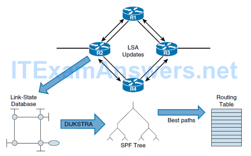
Establish neighbor adjacencies
- OSPF-enabled routers must form adjacencies with their neighbor before they can share information with that neighbor.
- An OSPF enabled router sends Hello packets out all OSPF-enabled interfaces to determine whether neighbors are present on those links.
- If a neighbor is present, the OSPF enabled router attempts to establish a neighbor adjacency with that neighbor.
Exchange link-state advertisements
- After adjacencies are established, routers then exchange link-state advertisements (LSAs).
- LSAs contain the state and cost of each directly connected link.
- Routers flood their LSAs to adjacent neighbors. Adjacent neighbors receiving the LSA immediately flood the LSA to other directly connected neighbors, until all routers in the area have all LSAs.
Build the topology table
- After the LSAs are received, OSPF-enabled routers build the topology table (LSDB) based on the received LSAs.
- This database eventually holds all the information about the topology of the network.
- It is important that all routers in the area have the same information in their LSDBs.
Execute the SPF algorithm
- Routers then execute the SPF algorithm. The SPF algorithm creates the SPF tree.
Build the routing table
- From the SPF tree, the best paths are inserted into the routing table. Routing decisions are made based on the entries in the routing table.
Hierarchical Structure of OSPF
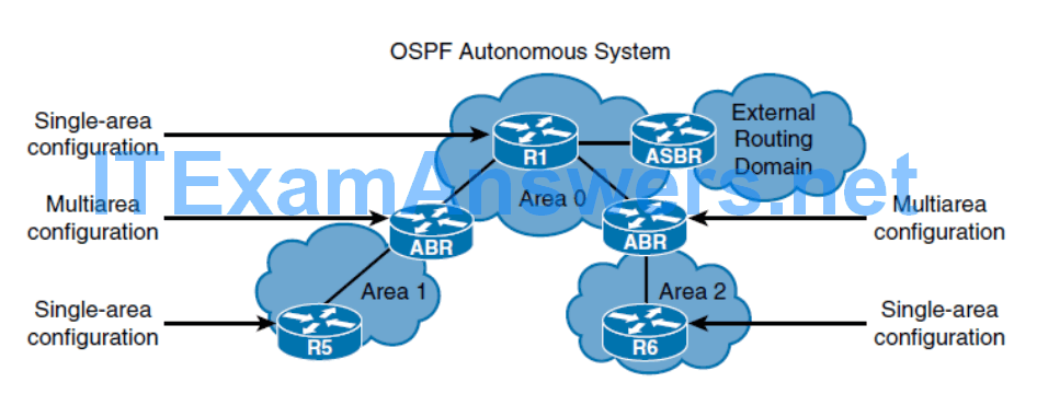
OSPF uses a two-layer area hierarchy:
Backbone area, transit area or area 0
- Two principal requirements for the backbone area are that it must connect to all other nonbackbone areas and this area must be always contiguous; it is not allowed to have split up the backbone area.
- Generally, end users are not found within a backbone area.
Nonbackbone area
- The primary function of this area is to connect end users and resources. Nonbackbone areas are usually set up according to functional or geographic groupings.
- Traffic between different nonbackbone areas must always pass through the backbone area.
In the multi-area topology there are special commonly OSPF terms:
ABR
- A router that has interfaces connected to at least two different OSPF areas, including the backbone area. ABRs contain LSDB information for each area, make route calculation for each area and advertise routing information between areas.
ASBR
- ASBR is a router that has at least one of its interfaces connected to an OSPF area and at least one of its interfaces connected to an external non-OSPF domain.
Internal router
- A router that has all its interfaces connected to only one OSPF area.
Backbone router
- A router that has at least one interface connected to the backbone area.
OSPF Message Types
Type 1: Hello packet: Hello packets are used to discover, build, and maintain OSPF neighbor adjacencies.
Type 2: Database Description (DBD) packet: When the OSPF neighbor adjacency is already established, a DBD packet is used to describe LSDB so that routers can compare whether databases are in sync.
Type 3: Link-State Request (LSR) packet : The router will send an LSR packet to inform OSPF neighbors to send the most recent version of the missing LSAs.
Type 4: Link-State Update (LSU) packet : LSU packets are used for the flooding of LSAs and sending LSA responses to LSR packets.
Type 5: Link-State Acknowledgment (LSAck) packet : LSAcks are used to make flooding of LSAs reliable.
- Type 3: Link-State Request (LSR) packet It is sent only to the directly connected neighbors who have previously requested LSAs in the form of LSR packet. In case of flooding, neighbor routers are responsible for re-encapsulation of received LSA information in new LSU packets.
- Type 5: Link-State Acknowledgment (LSAck) packet : Each LSA received must be explicitly acknowledged. Multiple LSAs can be acknowledged in a single LSAck packet.
Basic OSPF Configuration
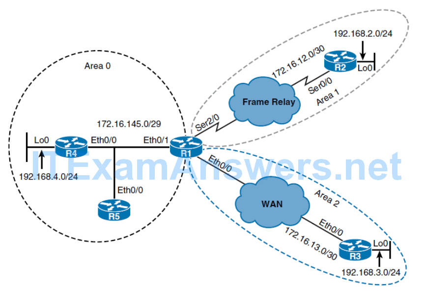
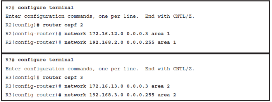
- To enable the OSPF process on the router, use the router ospf process-id command.
- Process ID numbers between neighbors do not need to match for the routers to establish an OSPF adjacency.
To enable the OSPF process on the router, use the router ospf process-id command. Process ID numbers between neighbors do not need to match for the routers to establish an OSPF adjacency. The OSPF process number ID is an internally used identification parameter for an OSPF routing process and only has local significance. However, it is good practice to make the process ID number the same on all routers. If necessary, you can specify multiple OSPF routing processes on a router, but you need to know the implications of doing so. Multiple OSPF processes on the same router is not common and beyond the scope of this book.
- To establish OSPF full adjacency, two neighbor routers must be in the same area.
- Any individual interface can only be attached to a single area.
If the address ranges specified for different areas overlap, IOS will adopt the first area in the network command list and ignore subsequent overlapping portions. To avoid conflicts, you must pay special attention to ensure that address ranges do not overlap.
Configuration of OSPF Router IDs
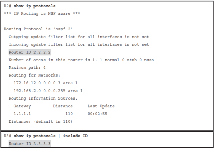
To choose the OSPF router ID at the time of OSPF process initialization, the router uses the following criteria:
- Use the router ID specified in the router-id ip-address command.
- Use the highest IPv4 address of all active loopback interfaces on the router.
- Use the highest IPv4 address among all active nonloopback interfaces.
At least one primary IPv4 address on an interface in the up/up state must be configured for a router to be able to choose router ID; otherwise, an error message is logged, and the OSPF process does not start.

You can configure an arbitrary value in the IPv4 address format, but this value must be unique. If the IPv4 address specified with the router-id command overlaps with the router ID of another already-active OSPF process, the router-id command fails.
The OSPF router ID is a fundamental parameter for the OSPF process. For the OSPF process to start, Cisco IOS must be able to identify a unique OSPF router ID. Similar to EIGRP, the OSPF router ID is a 32-bit value expressed as an IPv4 address. At least one primary IPv4 address on an interface in the up/up state must be configured for a router to be able to choose router ID; otherwise, an error message is logged, and the OSPF process does not start.
Clearing the OSPF Processes
- OSPF routing process can be cleared for the manually configured router ID to take effect.
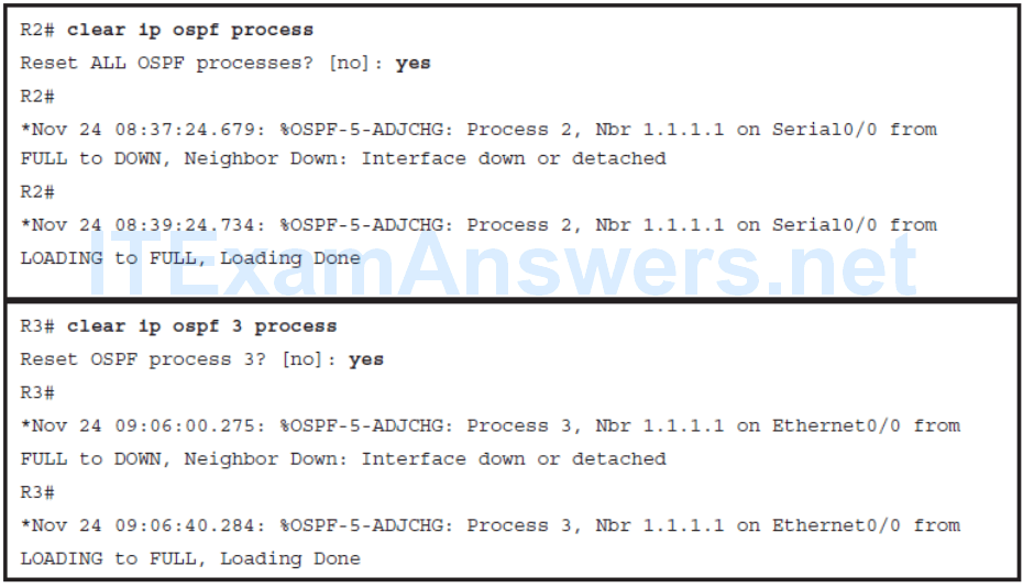
Once an OSPF router ID is selected, it is not changed even if the interface that is used to select it changed its operational state or its IP address. To change the OSPF router ID, you must reset the OSPF process with the clear ip ospf process command or reload the router. In production networks, the OSPF router ID cannot be changed easily. Changing the OSPF router ID requires reset of all OSPF adjacencies, resulting in a temporary routing outage. The router also has to originate new copies of all originating LSAs with the new router ID. You can either clear the specific OSPF process by specifying the process ID, or you can reset all OSPF processes by using the clear ip ospf process command.
OSPF Router ID Criteria
1.Use the router ID specified in the router-id ip-address command.
- You can configure an arbitrary value in the IPv4 address format, but this value must be unique.
- If the IPv4 address specified with the router-id command overlaps with the router ID of another already-active OSPF process, the router-id command fails.
2.Use the highest IPv4 address of all active loopback interfaces on the router.
3.Use the highest IPv4 address among all active nonloopback interfaces.
Verifying the Router IDs
Verifying OSPF Neighborships

- Neighbor ID : Represents neighbor router ID.
- Priority : Priority on the neighbor interface used for the DR/BDR election.
- State : OSPF neighbor establishment process
- Dead Time : Represents value of the dead timer
- Address : Primary IPv4 address of the neighbor router.
- Interface : Local interface over which an OSPF neighbor relationship is established.
State : OSPF neighbor establishment process and denotes that the local router has established full neighbor adjacency with the remote OSPF neighbor. DR means that DR/BDR election process has been completed and that the remote router with the router ID 1.1.1.1 has been elected as the designated router (DR).
Dead Time : Represents value of the dead timer. When this timer expires, the router terminates the neighbor relationship. Each time a router receives an OSPF Hello packet from a specific neighbor, it resets the dead timer back to its full value.
Verifying the OSPF-Enabled Interfaces
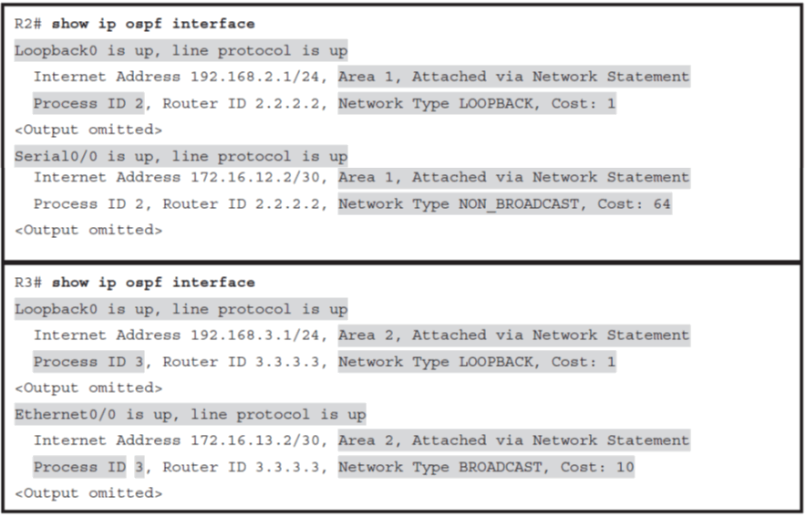
Output of the show ip ospf interface command shows you all interfaces enabled in the OSPF process. For each enabled interface, you can see detailed information such as OSPF area ID, OSPF process ID, and how the interface was included into the OSPF process. In the output, you can see that both interfaces on both routers were included via the network statement, configured with the network command.
Verifying the OSPF Routes
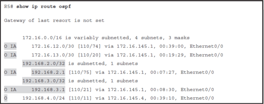
Among the routes originated within the OSPF autonomous system, OSPF clearly distinguishes two types of routes: intra-area routes and interarea routes.
To change this default behavior, you can optionally change OSPF network type on the loopback interface from the default loopback to point-topoint using the ip ospf network point-to-point interface command.
OSPF Routes
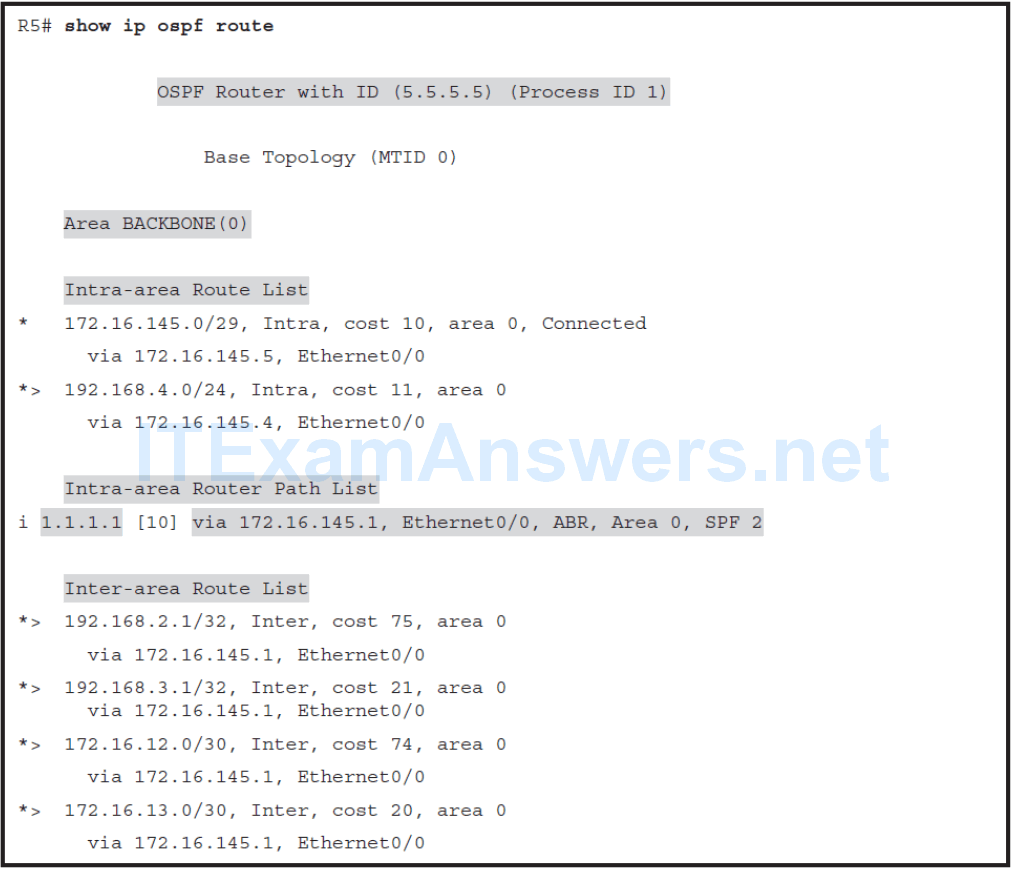
The show ip ospf route command clearly separates the lists of intra-area and inter-area routes. In addition, output of the command displays essential information about ABRs, including the router ID, IPv4 address in the current area, interface that advertises routes into the area, and the area ID.
OSPF Adjacency Establishment Steps
- Down state – the initial state of a neighbor conversation that indicates that no Hello’s have been heard from the neighbor.
- Init state – a router receives a Hello from the neighbor but has not yet seen its own router ID in the neighbor Hello packet
- 2-Way state – When the router sees its own router ID in the Hello packet received from the neighbor
- ExStart state – In the DBD exchange process, the router with the higher router ID will become master, and it will be the only router that can increment sequence numbers. With master/slave selection complete, database exchange can start
- Exchange state – To describe the content of the database, one or multiple DBD packets may be exchanged. A router compares the content of its own Database Summary list with the list received from the neighbor, and if there are differences, it adds missing LSAs to the Link State Request list.
- Loading state – LSR packet is sent to the neighbor requesting full content of the missing LSAs from the LS Request list
- Full state – Finally, when neighbors have a complete version of the LSDB, which means that databases on the routers are synchronized and that neighbors are fully adjacent.
On broadcast links, OSPF neighbors first determine the designated router (DR) and backup designated router (BDR) roles, which optimize the exchange of information in broadcast segments. In the next step, routers start to exchange content of OSPF databases. The first phase of this process is to determine master/slave relationship and choose the initial sequence number for adjacency formation. To accomplish this, routers exchange DBD packets. When the router receives the initial DBD packet it transitions the state of the neighbor from which this packet is received to ExStart state, populates its Database Summary list with the LSAs that describe content of the neighbor’s database, and sends its own empty DBD packet. In the DBD exchange process, the router with the higher router ID will become master, and it will be the only router that can increment sequence numbers. With master/slave selection complete, database exchange can start
Optimizing OSPF Adjacency Behavior
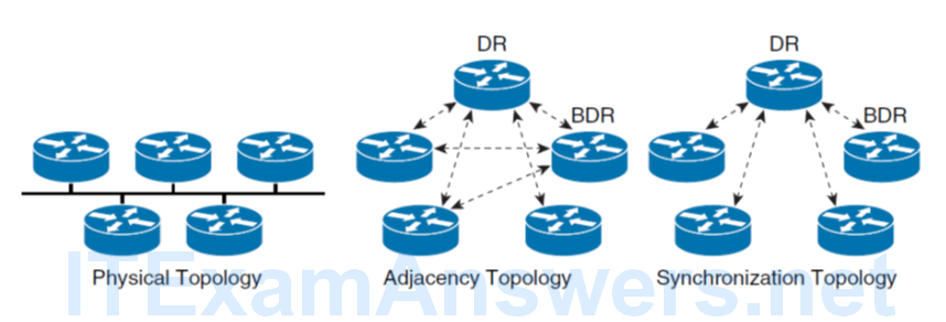
As the number of routers on the segment grows, the number of OSPF adjacencies increases exponentially. Every router must synchronize its OSPF database with every other router, and in the case of a large number of routers, this leads to inefficiency.
OSPF Adjacencies on Multiaccess Networks
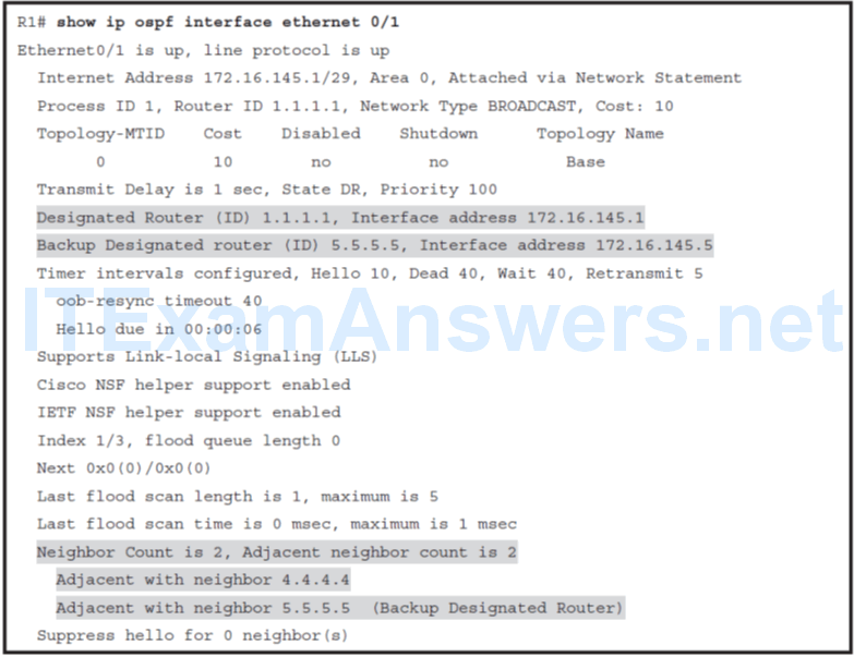
The routers on the multiaccess segment elect a designated router (DR) and backup designated router (BDR), which centralizes communications for all routers connected to the segment.
The DR and BDR improve network functioning in the following ways:
- Reducing routing update traffic: The DR and BDR act as a central point of contact for link-state information exchange on a multiaccess network; therefore, each router must establish a full adjacency with the DR and the BDR only.
- Managing link-state synchronization: The DR and BDR ensure that the other routers on the network have the same link-state information about the common segment.
Only LSAs are sent to the DR/BDR. The normal routing of packets on the segment will go to the best next-hop router.
- Only LSAs are sent to the DR/BDR. The normal routing of packets on the segment will go to the best next-hop router.
- When the DR is operating, the BDR does not perform any DR functions. Instead, the BDR receives all the information, but the DR performs the LSA forwarding and LSDB synchronization tasks.
- The BDR performs the DR tasks only if the DR fails.
- When the DR fails, the BDR automatically becomes the new DR, and a new BDR election occurs.
Neighbor Status
DR/BDR Election Process
- The DR/BDR election process takes place on broadcast and NBMA networks.
- Routers send OSPF Hello packets to discover which OSPF neighbors are active on the common Ethernet segment.
- Once OSPF neighbors are in the 2-Way state, the DR/BDR election process begins.
- The OSPF Hello packet contains three specific fields used for the DR/BDR election:
- Designated Router, Backup Designated Router, and Router Priority.
- From all routers listed in this fields, the router with the highest priority becomes the DR, and the one with the next highest priority becomes the BDR.
- If the priority values are equal, the router with the highest OSPF router ID becomes the DR, and the one with the next highest OSPF router ID becomes the BDR.
The Designated Router and Backup Designate Router fields are populated with a list of routers claiming to be DR and BDR.
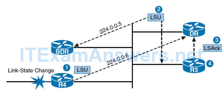
- On the multiaccess broadcast networks, routers use multicast destination IPv4 address 224.0.0.6 to communicate with the DR , and the DR uses multicast destination IPv4 address 224.0.0.5 to communicate with all other non-DR routers
- On NBMA networks, the DR and adjacent routers communicate using unicast addresses.
- The DR/BDR election process not only occurs when the network first becomes active but also when the DR becomes unavailable.
- In this case, the BDR will immediately become the DR, and the election of the new BDR starts.
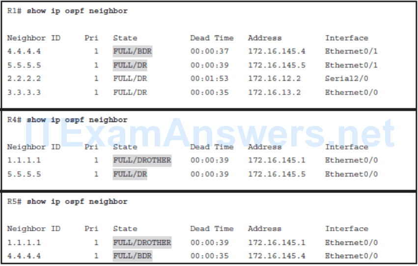
- On the multi-access segment, it is normal behavior that the router in DROTHER status is fully adjacent with DR/BDR and in 2-WAY state with all other DROTHER routers present on the segment.
Using OSPF Priority in the DR/BDR Election
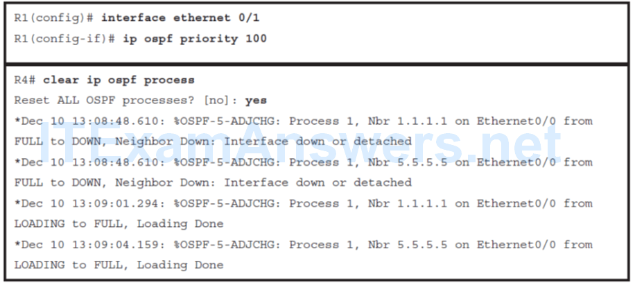
Every broadcast and NBMA OSPF-enabled interface is assigned a priority value between 0 and 255. By default, the OSPF interface priority is 1 and can be manually changed by using the ip ospf priority interface command.
- The router with the highest priority value is elected as the DR.
- The router with the second-highest priority value is the BDR.
- In case of a tie where two routers have the same priority value, router ID is used as the tiebreaker. The router with the highest router ID becomes the DR. The router with the second-highest router ID becomes the BDR.
- A router with a priority that is set to 0 cannot become the DR or BDR. A router that is not the DR or BDR is called a DROTHER.
Configuring the OSPF Priority on an Interface
Verifying OSPF Neighbor Status
OSPF Behavior in NBMA Hub-and-Spoke Topology
OSPF treats NBMA environments like any other broadcast media environment, such as Ethernet; however, NBMA clouds are usually built as hub-and-spoke topologies using private virtual circuits (PVCs) or switched virtual circuits (SVCs)
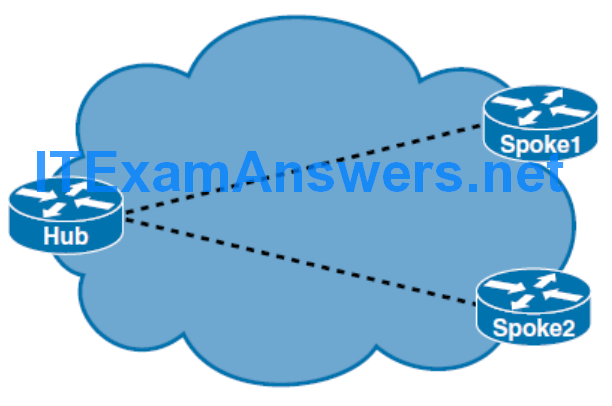
In these cases, the physical topology does not provide multiaccess capability, on which OSPF relies. In a hub-and-spoke NBMA environment, you will need to have the hub router acting as the DR and spoke routers acting as the DROTHER routers. On the spoke router interfaces, you want to configure an OSPF priority value of 0 so that the spoke routers never participate in the DR election.

The Importance of MTU
- If neighbors have a mismatched IPv4 MTU configured, they will not be able to form full OSPF adjacency.
- Mismatched neighbors will stay in ExStart state
- By default, the IPv6 MTU must also match between OSPFv3 neighbors. However, you can override this by using the ospfv3 mtu-ignore interface command.
Manipulating OSPF Timers
- Similar to EIGRP, OSPF uses two timers to check neighbor reachability: the hello and dead intervals.
- OSPF requires that both hello and dead timers be identical for all routers on the segment to become OSPF neighbors.
- The default value of the OSPF hello timer on multi-access broadcast and point-to-point links is 10 seconds, and is 40 seconds on all other network types, including NBMA.
- When you configure the hello interval, the default value of the dead interval is automatically adjusted to four times the hello interval.
- For broadcast and point-to-point links, it is 30 seconds, and for all other OSPF network types, it is 120 seconds.
Examining the Hello/Dead Timers
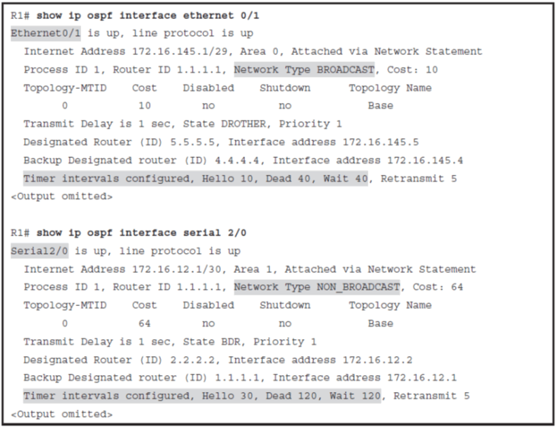
Modifying the Hello and Dead Intervals

OSPF Relationship over Point-to-Point Links
- The routers dynamically detects its neighboring routers by multicasting its Hello packets to all OSPF routers, using the 224.0.0.5 address.
- No DR or BDR election is performed
- The default OSPF hello and dead timers on point-to-point links are 10 seconds and 40 seconds, respectively.

OSPF Neighbor Relationship over MPLS
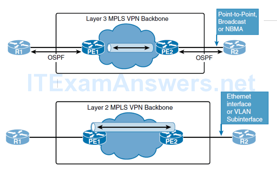
- To OSPF, the Layer 3 MPLS VPN backbone looks like a standard corporate backbone that runs standard IP routing software. Routing updates are exchanged between the customer routers and the PE routers that appear as normal routers in the customer network. OSPF is enabled on proper interfaces by using the network command. The standard design rules that are used for enterprise Layer 3 MPLS VPN backbones can be applied to the design of the customer network. The service provider routers are hidden from the customer view, and CE routers are unaware of MPLS VPN. Therefore, the internal topology of the Layer 3 MPLS backbone is totally transparent to the customer. The PE routers receive IPv4 routing updates from the CE routers and install them in the appropriate virtual routing and forwarding (VRF) table. This part of the configuration, and operation, is the responsibility of a service provider.
- The PE-CE can have any OSPF network type: point-to-point, broadcast, or even nonbroadcast multiaccess.
- The only difference between a PE-CE design and a regular OSPF design is that the customer has to agree with the service provider about the OSPF parameters (area ID, authentication password, and so on); usually, these parameters are governed by the service provider.
- In a MPLS L2 VPN a neighbor relationship is established between R1 and R2 directly, and it behaves in the same way as on a regular Ethernet broadcast network.
OSPF Neighbor States
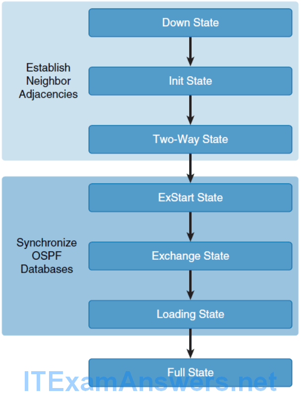
- Down: No information has been received on the segment.
- Init: The interface has detected a Hello packet coming from a neighbor, but bidirectional
- 2-Way: There is bidirectional communication with a neighbor. The router has seen itself in the Hello packets coming from a neighbor
- ExStart: Routers are trying to establish the initial sequence number that is going to be used in the information exchange packets.
- Exchange: Routers will describe their entire LSDB by sending database description (DBD) packets.
- Loading: In this state, routers are finalizing the information exchange.
- Full: In this state, adjacency is complete.
OSPF Network Types
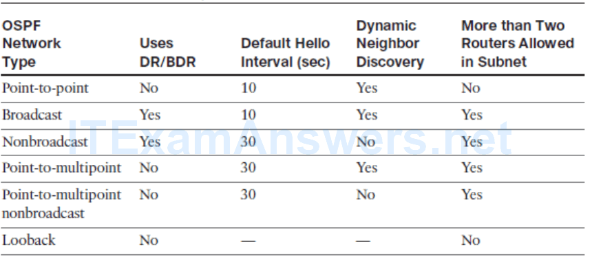
- Point-to-point: Routers use multicast to dynamically discover neighbors. There is no DR/BDR electio. It is a default OSPF network type for serial links and point-to-point Frame Relay subinterfaces.
- Broadcast: Multicast is used to dynamically discover neighbors. The DR and BDR are elected. It is a default OSPF network type for Ethernet links.
- Nonbroadcast: Used on networks that interconnect more than two routers but without broadcast capability. Neighbors must be statically configured, followed by DR/BDR election. This network type is the default for all physical interfaces and multipoint subinterfaces using Frame Relay encapsulation.
- Point-to-multipoint: OSPF treats this network type as a logical collection of point-to- point links even though all interfaces belong to the common IP subnet. Every interface IP address will appear in the routing table of the neighbors as a host /32 route. Neighbors are discovered dynamically using multicast. No DR/BDR election occurs.
- Point-to-multipoint nonbroadcast: Cisco extension that has the same characteristics as point-to-multipoint type except for the fact that neighbors are not discovered dynamically. Neighbors must be statically defined, and unicast is used for communication.
- Loopback: Default network type on loopback interfaces.
Configuring Passive Interfaces

Building the Link-State Database
- List and describe different LSA types
- Describe how OSPF LSAs are also reflooded at periodic intervals
- Describe the exchange of information in a network without a designated router
- Describe the exchange of information in a network with a designated router
- Explain when SPF algorithms occur
- Describe how the cost of intra-area routes is calculated
- Describe how the cost of interarea routes is calculated
- Describe rules selecting between intra-area and interarea routes
OSPF LSA Types
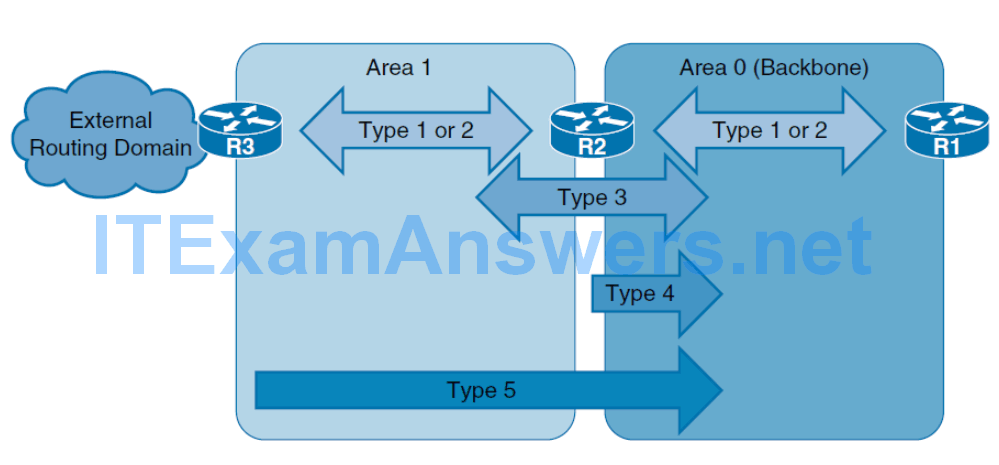
- Type 1, Router LSA: Every router generates router link advertisements for each area to which it belongs. Router link advertisements describe the state of the router links to the area and are flooded only within that particular area. The link-state ID of the type 1 LSA is the originating router ID.
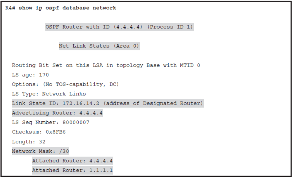
- Type 2, Network LSA: DRs generate network link advertisements for multi-access networks. Network link advertisements describe the set of routers that are attached to a particular multiaccess network. Network link advertisements are flooded in the area that contains the network. The link-state ID of the type 2 LSA is the IP interface address of the DR.
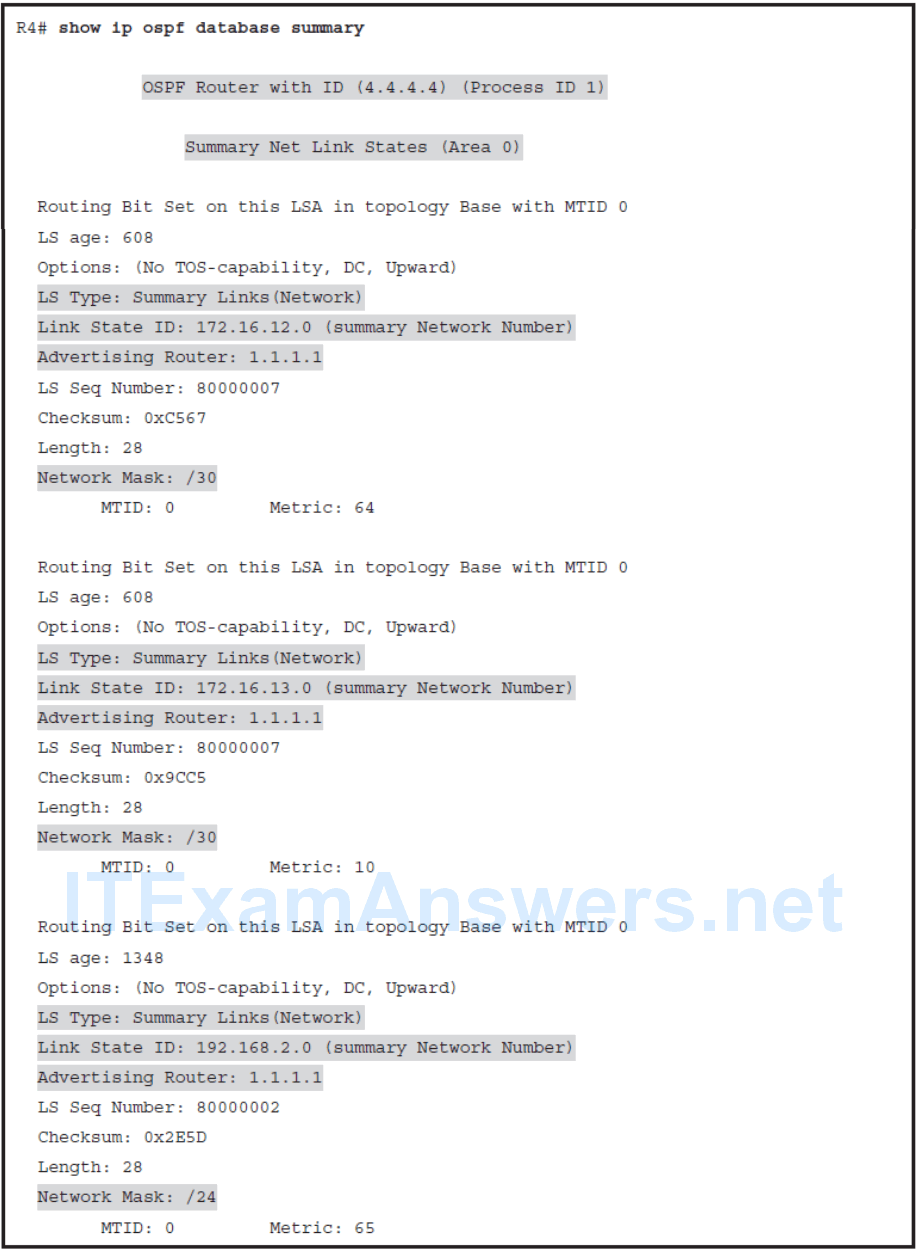
- Type 3, Summary LSA: An ABR takes the information that it learned in one area and describes and summarizes it for another area in the summary link advertisement. This summarization is not on by default. The link-state ID of the type 3 LSA is the destination network number.
- Type 4, ASBR Summary LSA: The ASBR summary link advertisement informs the rest of the OSPF domain how to get to the ASBR. The link-state ID includes the router ID of the described ASBR.
- Type 5, Autonomous System LSA: Autonomous system external link advertisements, which are generated by ASBRs, describe routes to destinations that are external to the autonomous system. They get flooded everywhere, except into special areas. The link-state ID of the type 5 LSA is the external network number.
Other LSA Types
- Type 6: Specialized LSAs that are used in multicast OSPF applications
- Type 7: Used in special area type NSSA for external routes
- Type 8, 9: Used in OSPFv3 for link-local addresses and intra-area prefix
- Type 10, 11: Generic LSAs, also called opaque , which allow future extensions of OSPF
Examining the OSPF Link-State Database
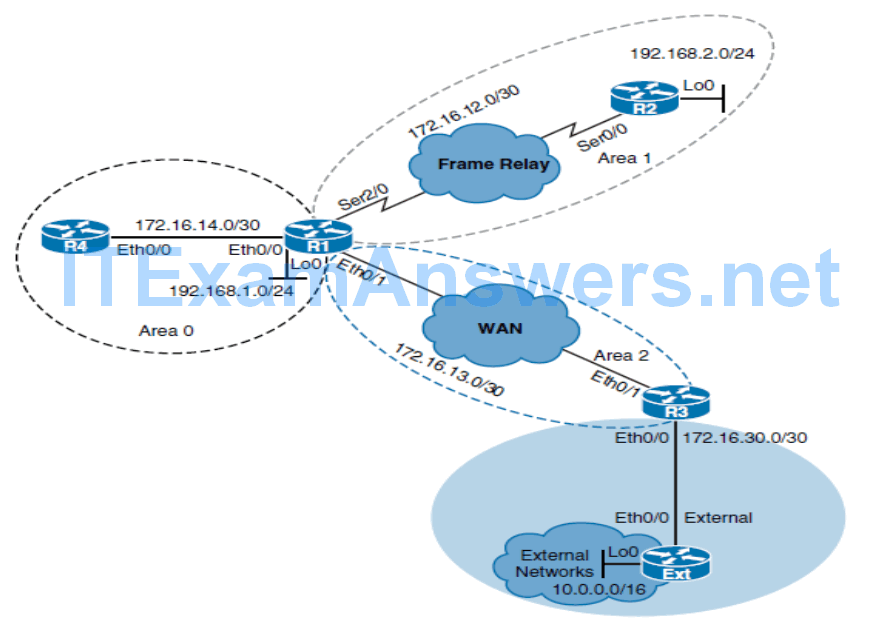
Routing Table
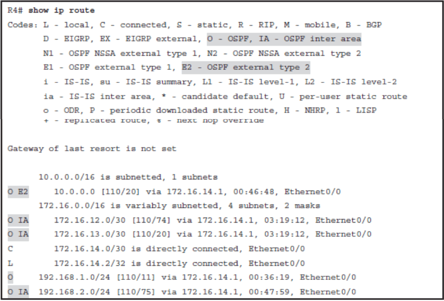
OSPF LSDB
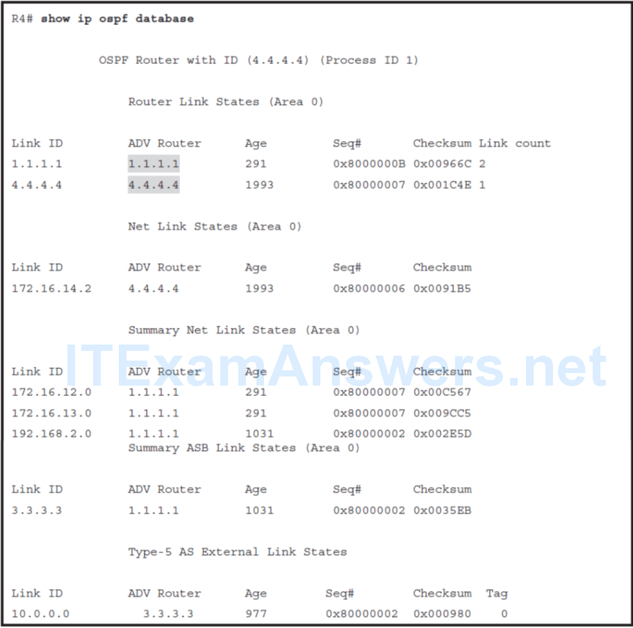
Type 1 LSA Details
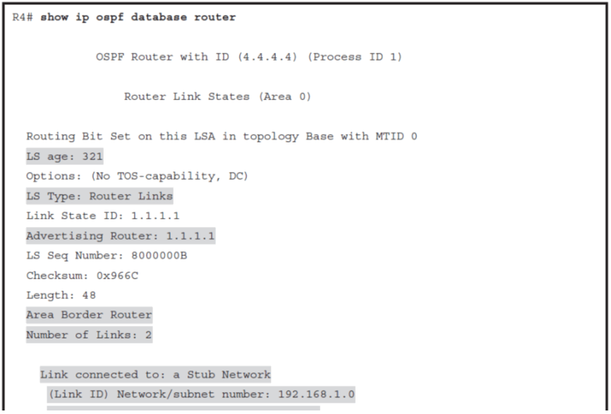
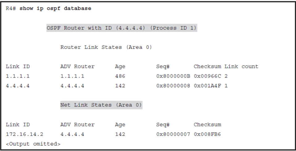
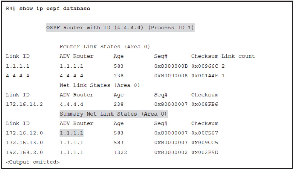
- The OSPF database contains all LSAs that describe the network topology. The show ip ospf database command displays the content of the LSDB and verifies information about specific LSAs.
- The output reveals the presence of different LSA types. For each LSA type, you can see which router advertised it, the age of the LSA, and the value of the link ID.
- In Example 3-26 , notice two different type 1 LSAs, or router link advertisements, generated by routers with router ID 1.1.1.1 and 4.4.4.4.
- The content of the displayed LSA reveals that R1 is an ABR with two links.
Locally Generated Type 1 LSAs
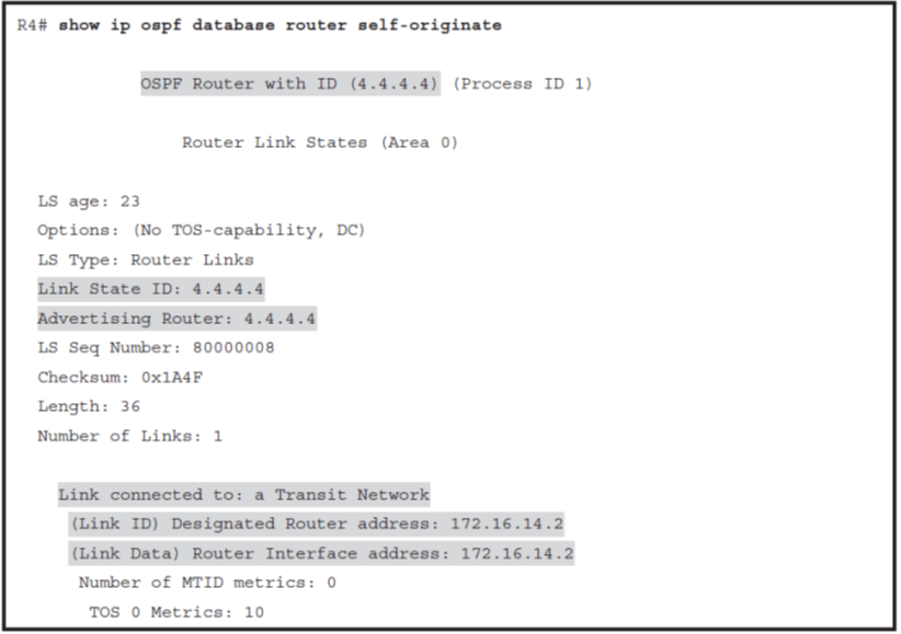
Type 1 LSA
- Type 1 LSAs are generated by every router and flooded within the area.
- They describe the state of the router links in that area.
- When generating a type 1 LSA, the router uses its own router ID as the value of LSID.
OSPF Type 2 Network LSA
Type 2 LSA
- The DR of the network is responsible for advertising the network LSA
- A type 2 network LSA lists each of the attached routers that make up the transit network, including the DR itself, and the subnet mask that is used on the link.
- The type 2 LSA then floods to all routers within the transit network area
- Type 2 LSAs never cross an area boundary.
- The LSID for a network LSA is the IP interface address of the DR that advertises it

OSPF Type 3 Summary LSA
Type 3 LSA
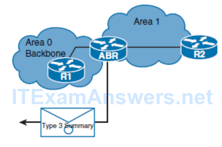
- The ABRs generate type 3 summary LSAs to describe any networks that are owned by an area to the rest of the areas in the OSPF autonomous system
- Summary LSAs are flooded throughout a single area only, but are regenerated by ABRs to flood into other areas.
- By default, OSPF does not automatically summarize groups of contiguous subnets.
- As a best practice, you can use manual route summarization on ABRs to limit the amount of information that is exchanged between the areas.

OSPF Type 4 ASBR Summary LSA
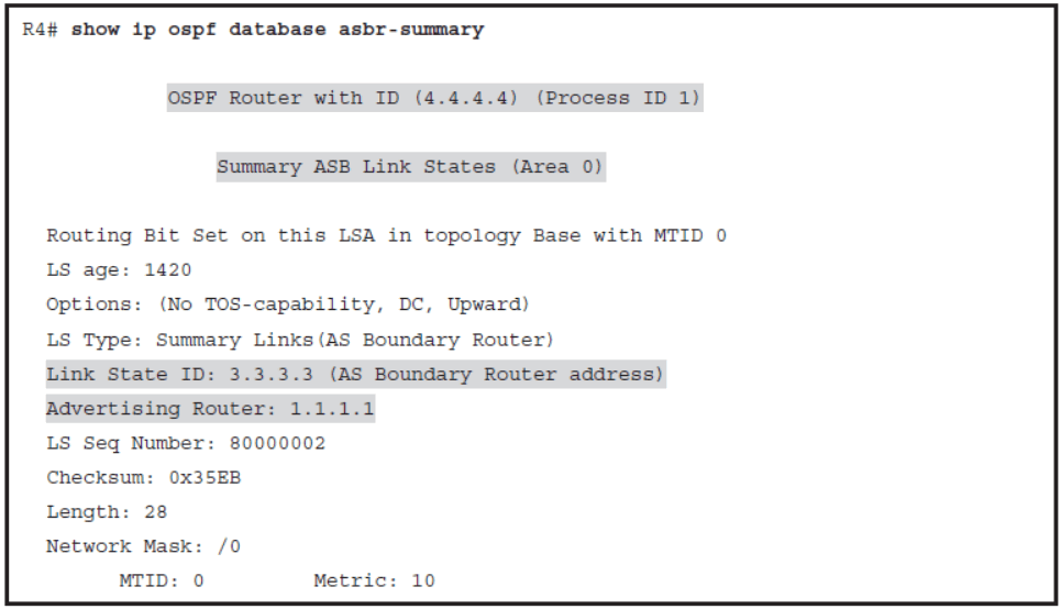
Type 4 LSA
- A type 4 LSA identifies the ASBR and provides a route to the ASBR.
- The link-state ID is set to the ASBR router ID.
- All traffic that is destined to an external autonomous system requires routing table knowledge of the ASBR that originated the external routes.

In the figure, the ASBR sends a type 1 router LSA with a bit (known as the external bit ) that is set to identify itself as an ASBR. When the ABR (identified with the border bit in the router LSA) receives this type 1 LSA, it builds a type 4 LSA and floods it to the backbone, area 0. Subsequent ABRs regenerate a type 4 LSA to flood it into their areas.
OSPF Type 5 External LSA
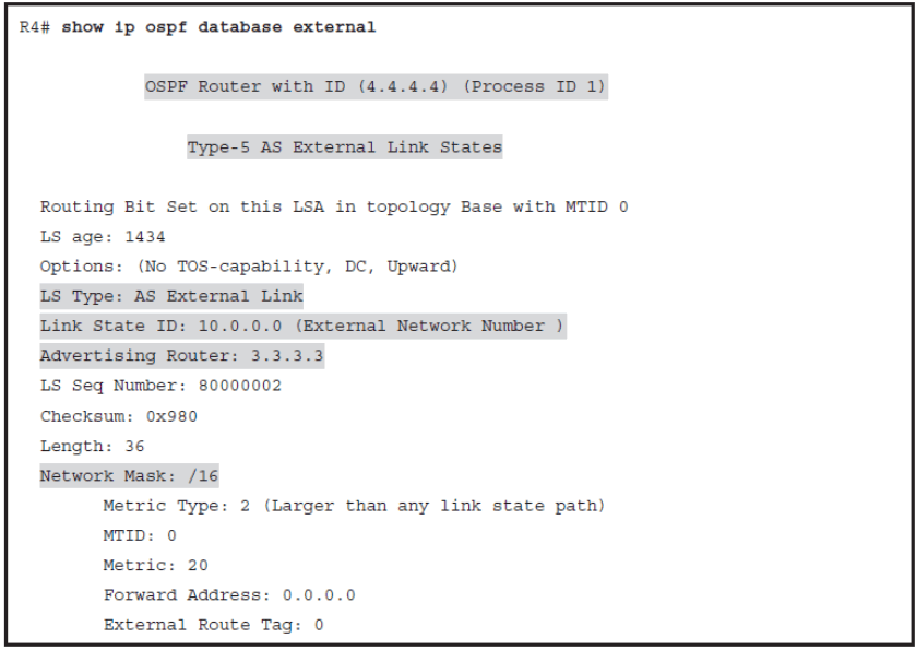
An external LSA on R4 describes the external network 10.0.0.0 with the subnet mask /16. The LSA is advertised by the R3 with a router ID 3.3.3.3. The zero forwarding address tells the rest of the routers in the OSPF domain that ASBR itself is the gateway to get to the external routes.
Type 5 LSA
- The LSID is the external network number.
- Information described in the type 5 LSA combined with the information received in the type 4 LSA, which describes the ASBR capability of router R3. This way, R4 learns how to reach the external networks.

Because of the flooding scope and depending on the number of external networks, the default lack of route summarization can also be a major issue with external LSAs. Therefore, you should consider summarization of external network numbers at the ASBR to reduce flooding problems.
Periodic OSPF Database Changes
- Although OSPF does not refresh routing updates periodically, it does reflood LSAs every 30 minutes.
- Each LSA includes the link-state age variable, which counts the age of the LSA packet
- In a normally operating network, you will not see the age variable with values higher than 1800 seconds.
- When an LSA reaches a max age of 60 minutes in the LSDB, it is removed from the LSDB, and the router will perform a new SPF calculation
- The router floods the LSA to other routers, informing them to remove the LSA as well.
- Because this update is only used to refresh the LSDB, it is sometimes called a paranoid update
Each LSA includes the link-state age variable, which counts the age of the LSA packet. When a network change occurs, the LSA’s advertising router generates an updated LSA to reflect the change in the network topology.
Exchanging and Synchronizing LSDBs
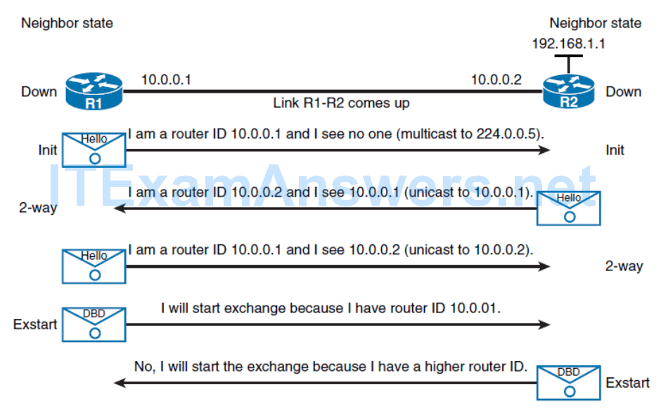
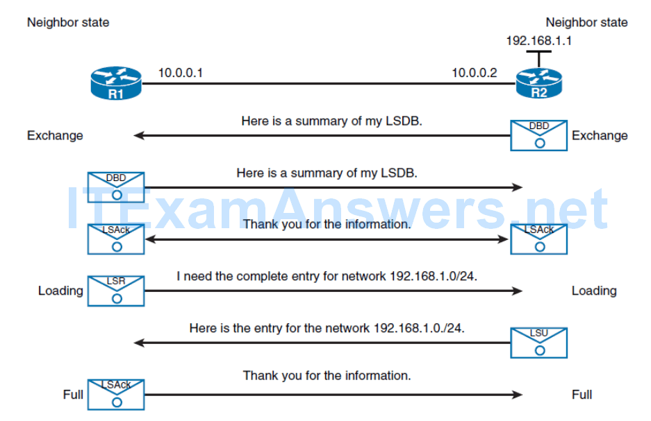
Synchronizing the LSDB on Multiaccess Networks
- When routers form a neighbor relationship on a multiaccess segment, the DR and BDR election takes place when routers are in the 2-Way state.
- The router with a highest OSPF priority, or highest router ID in case of a tie, is elected as a DR. Similarly, the router with the second highest priority or router ID becomes the BDR.
- While the DR and BDR proceed in establishing the neighborship with all routers on the segment, other routers establish full adjacency only with the DR and BDR.
- The neighbor state of other neighbors stays in the 2-Way state.
- Non-DR router exchange their databases only with the DR.
- The DR takes care to synchronize any new or changed LSAs with the rest of the routers on the segment.
Running the SPF Algorithm
- Every time there is a change in the network topology, OSPF needs to reevaluate its shortest path calculations. OSPF uses SPF to determine best paths toward destinations.
- The network topology that is described in the LSDB is used as an input for calculation.
- Network topology change can influence best path selection; therefore, routers must rerun SPF each time there is an intra-area topology change.
- Interarea changes, which are described in type 3 LSAs, do not trigger the SPF recalculation because the input information for the best path calculation remains unchanged.
- The router determines the best paths for interarea routes based on the calculation of the best path toward the ABR.
Verifying OSPF Frequency of the SPF Algorithm

OSPF Best Path Calculation
- Once LSDBs are synchronized among OSPF neighbors, each router needs to determine on its own the best paths over the network topology.
- SPF it compares total costs of specific paths against each other. The paths with the lowest costs are selected as the best paths.
- OSPF cost is computed automatically for each interface that is assigned into an OSPF process, using the following formula:
Cost = Reference bandwidth / Interface bandwidth
- The cost value is a 16-bit positive number between 1 and 65,535, where a lower value is a more desirable metric.
- Reference bandwidth is set to 100 Mbps by default.
- On high-bandwidth links (100 Mbps and more), automatic cost assignment no longer works
- “On these links, OSPF costs must be set manually on each interface.”
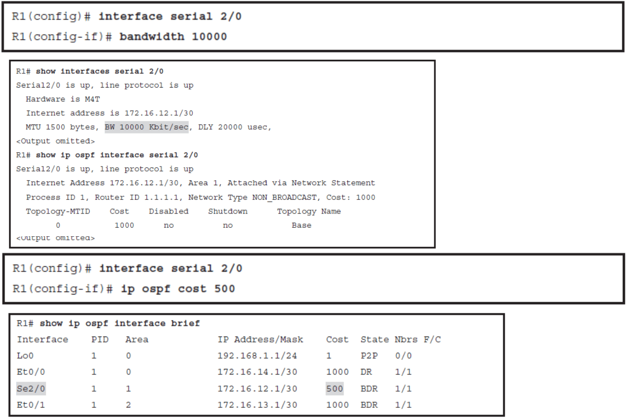
- The OSPF cost is recomputed after every bandwidth change, and the Dijkstra’s algorithm determines the best path by adding all link costs along a path.
Examining the Interface Bandwidth and OSPF Cost
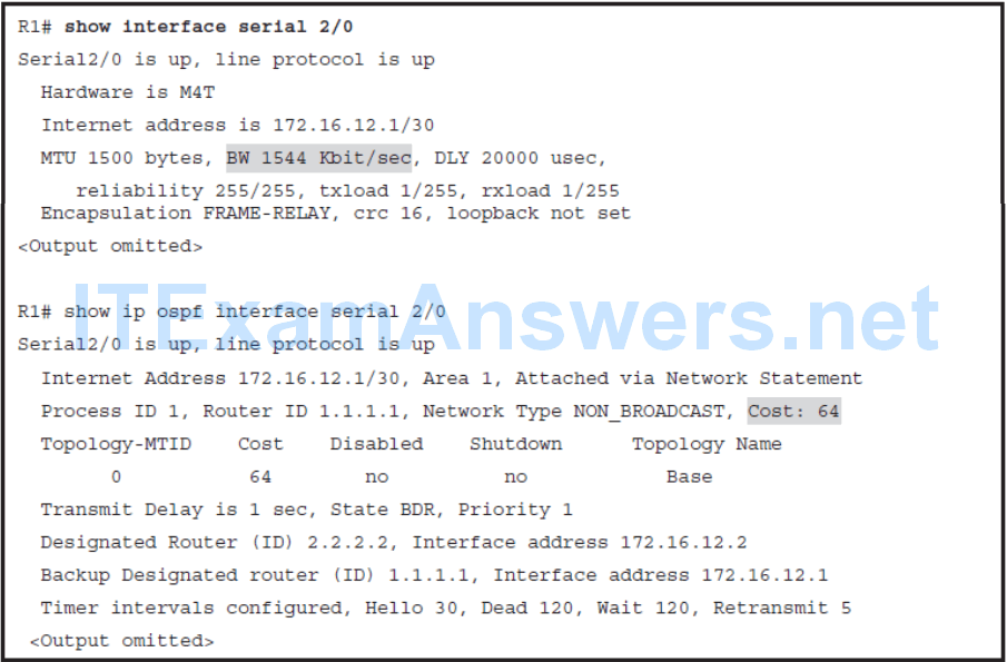
Default OSPF Costs

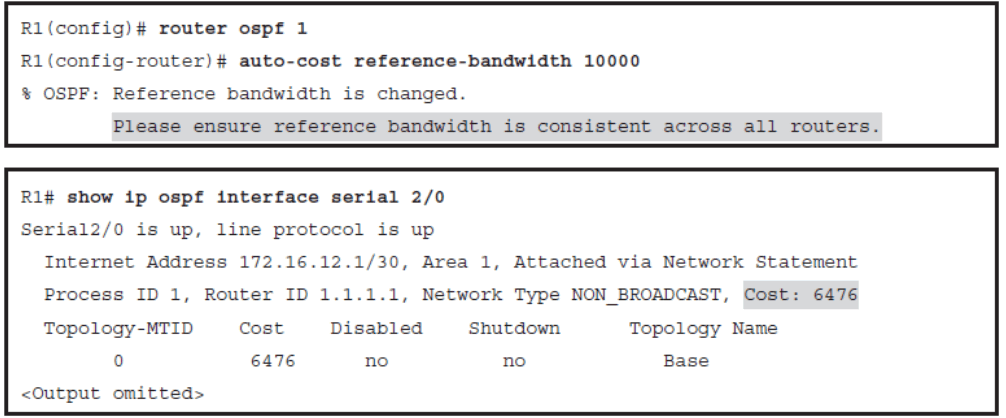
Modifying the Reference Bandwidth
Changing the Interface Bandwidth and OSPF Cost
Calculating the Cost of Intra-Area Routes
- To calculate the cost of intra-area routes, the router first analyzes OSPF database and identifies all subnets within its area.
- For each possible route, OSPF calculates the cost to reach the destination by summing up the individual interface costs.
- For each subnet, the route with the lowest total cost is selected as the best route.
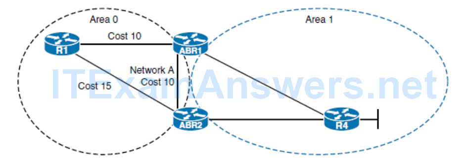
- Analyzing the topology in the Figure 3-21 from R1’s perspective, notice that it can reach intra-area network A either via ABR1 or ABR2. The autonomous system path through ABR1 is associated with the lower cost, so it will be selected as the best path.
- In a scenario where two paths would have the same lowest total cost, both routes would be selected as the best paths and inserted in the routing table. As a result, a router would perform equal-cost load balancing.
Calculating the Cost of Interarea Routes
- The internal OSPF router within an area receives only summarized info about interarea routes.
- As a result, the cost of an interarea route cannot be calculated the same way as for the intra-area routes.
- When ABRs propagate information about the interarea routes with type 3 LSAs, they include their lowest cost to reach a specific subnet in the advertisement.
- The internal router adds its cost to reach a specific ABR to the cost announced in a type 3 LSA.
- Then it selects the route with the lowest total cost as the best route.
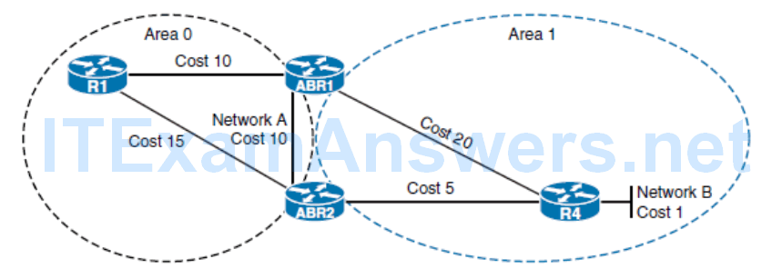
- Router R1, in Figure 3-22 , learns about network B from both ABRs. ABR2 in type 2 LSA reports the lowest cost to reach network B as 6, while ABR1 reports the cost of 21.
- Router R1 determines the lowest cost to reach both ABRs and adds this cost to the one received in LSA. Router R1 selects the route via ABR2 as the total lowest cost route and tries to install it into the routing table.
Selecting Between Intra-Area and Interarea Routes
- To eliminate the single point of failure on area borders, at least two ABRs are used in most networks.
- As a result, ABR can learn about a specific subnet from internal routers and also from the other ABR.
- ABR can learn an intra-area route and also an interarea route for the same destination.
- Even though the interarea route could have lower cost to the specific subnet, the intra-area path is always the preferred choice.
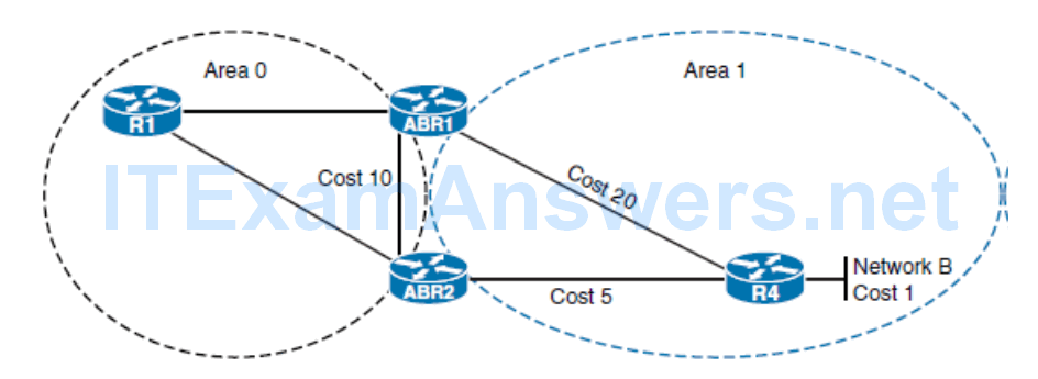
In the example topology in Figure 3-23 , ABR1 learns about network B directly from a router R4 and also from the ABR2. Even though the interarea path has a cost of 16, the intra-area path with a total cost of 21 is selected as the best path
Optimizing OSPF Behavior
- Describe the properties of OSPF route summarization
- Describe benefits of route summarization in OSPF
- Configure summarization on ABR
- Configure summarization on ASBR
- Configure the cost of OSPF default route
- Describe how you can use default routes and stub routing to direct traffic toward the Internet
- Describe the NSSA areas
- Configure the default route using the default-information originate command
OSPF Route Summarization
Route summarization is a key to scalability in OSPF.
Route summarization helps solve two major problems:
- Large routing tables
- Frequent LSA flooding throughout the autonomous system
Every time that a route disappears in one area, routers in other areas also get involved in shortest-path calculation.
To reduce the size of the area database, you can configure summarization on an area boundary or autonomous system boundary.
OSPF Route Summarization Process
- Normally, type 1 and type 2 LSAs are generated inside each area and translated into type 3 LSAs in other areas.
- With route summarization, the ABRs or ASBRs consolidate multiple routes into a single advertisement. ABRs summarize type 3 LSAs, and ASBRs summarize type 5 LSAs.
- Instead of advertising many specific prefixes, advertise only one summary prefix.
- Route summarization requires a good addressing plan—an assignment of subnets and addresses that is based on the OSPF area structure and lends itself to aggregation at the OSPF area borders.
If the OSPF design includes many ABRs or ASBRs, suboptimal routing is possible. This is one of the drawbacks of summarization.
Benefits of Route Summarization
- Route summarization directly affects the amount of bandwidth, CPU power, and memory resources that the OSPF routing process consumes.
- With route summarization, only the summarized routes are propagated into the backbone (area 0) increasing the stability of the network
- The routes being advertised in the type 3 LSAs are appropriately added to or deleted from the router’s routing table, but an SPF calculation is not done.
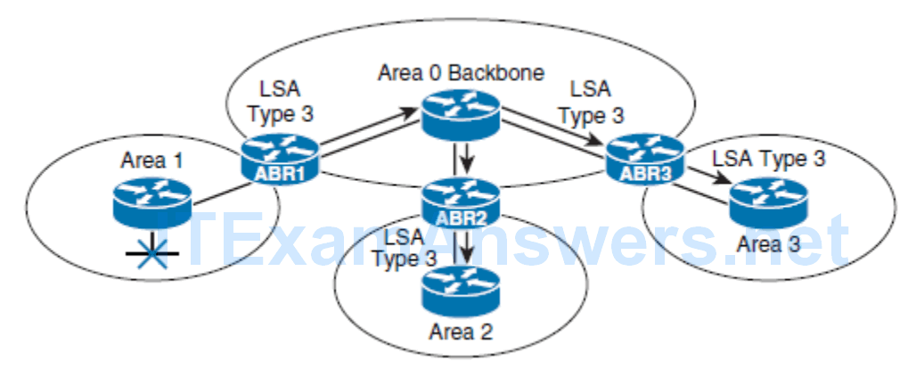
- Without route summarization, every specific-link LSA is propagated into the OSPF backbone and beyond, causing unnecessary network traffic and router overhead.
- Summarization prevents every router from having to rerun the SPF algorithm, increases the stability of the network, and reduces unnecessary LSA flooding.
- Also, if a network link fails, the topology change is not propagated into the backbone (and other areas by way of the backbone).
- Specific-link LSA flooding outside the area does not occur.
- Receiving a type 3 LSA into its area does not cause a router to run the SPF algorithm.
OSPF Route Summarization
OSPF offers two methods of route summarization:
- Summarization of internal routes performed on the ABRs
- Summarization of external routes performed on the ASBRs
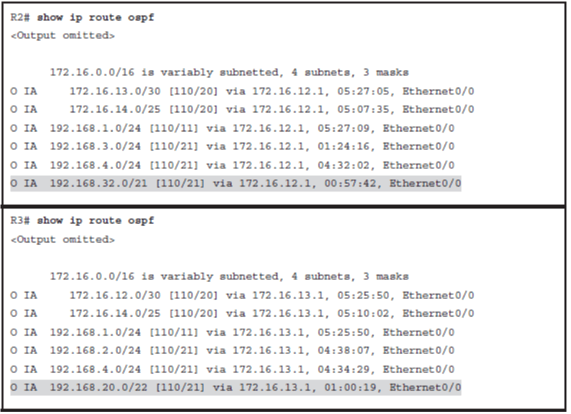
ABR’s Summarization
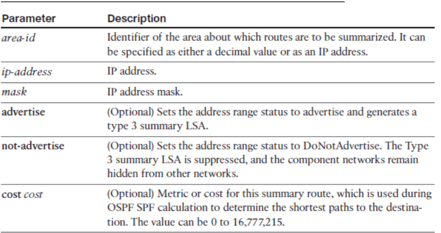
area area-id range ip-address mask [ advertise | not-advertise ] [ cost cost ]
Configuring OSPF Route Summarization
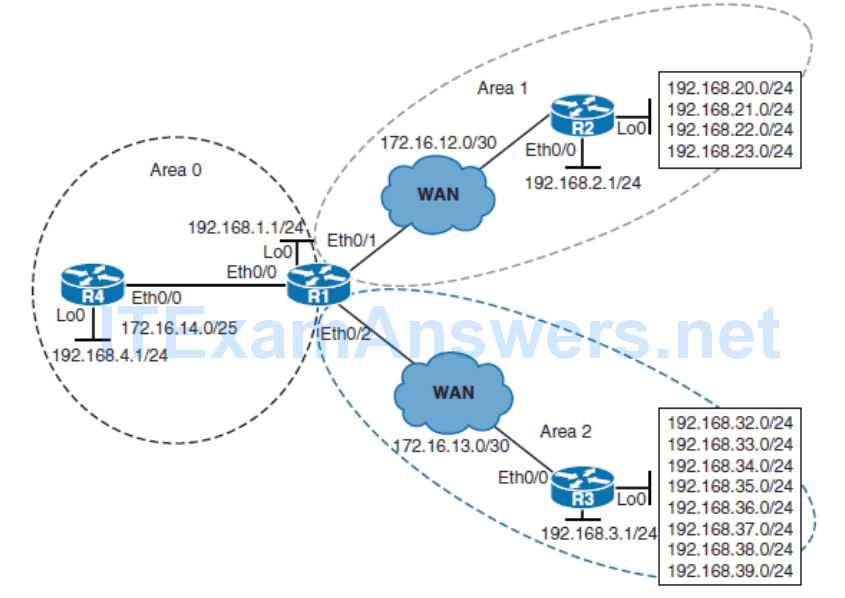
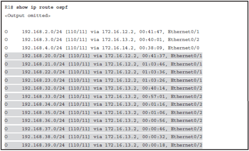
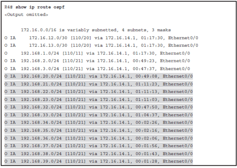
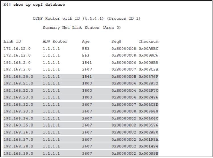
Configuring Summarization on the ABR
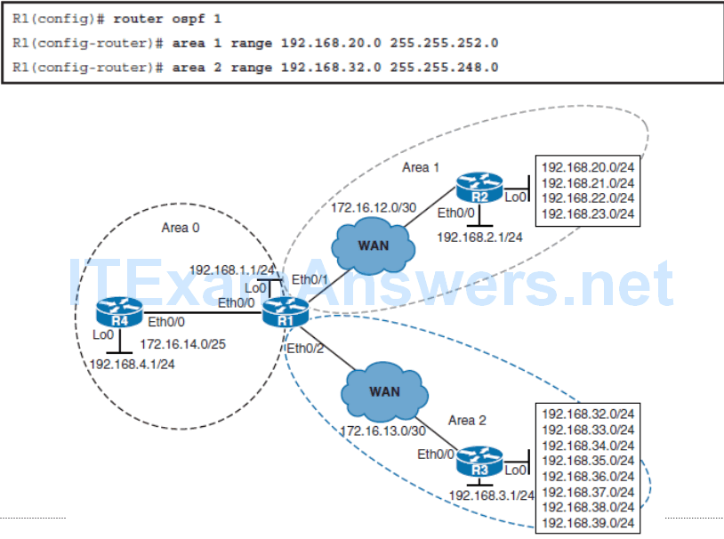
Configuring OSPF Route Summarization
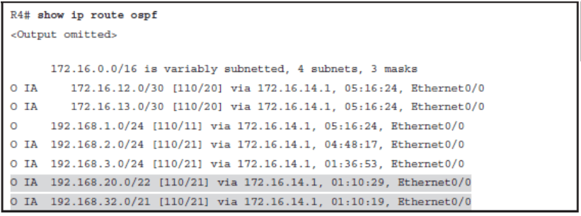
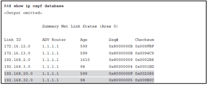
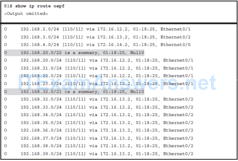
Summarization on ASBR’s
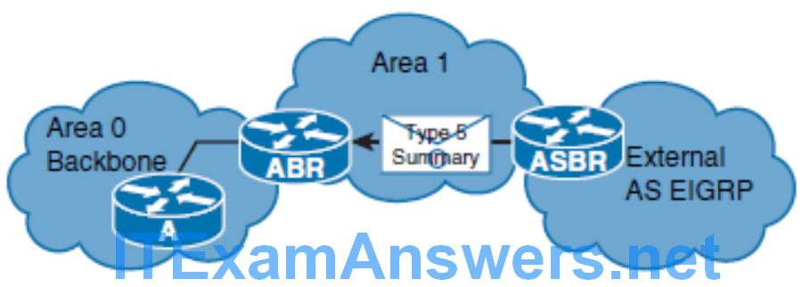
- summary-address {{ ip-address mask } | { prefix mask }} [ not-advertise ] [ tag tag ]
OSPF Virtual Links
- OSPF’s two-tiered area hierarchy requires that if more than one area is configured, one of the areas must be area 0, the backbone area.
- All other areas must be directly connected to area 0, and area 0 must be contiguous.
- OSPF expects all nonbackbone areas to inject routes into the backbone, so that the routes can be distributed to other areas.
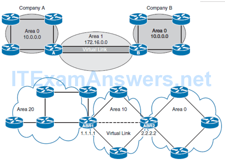
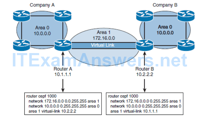
- A virtual link is a link that allows discontiguous area 0s to be connected, or a disconnected area to be connected to area 0, via a transit area.
The OSPF virtual link feature should be used only in very specific cases, for temporary connections or for backup after a failure. Virtual links should not be used as a primary backbone design feature.
Virtual Links Issues
- The OSPF virtual link feature should be used only in very specific cases, for temporary connections or for backup after a failure.
- Virtual links should not be used as a primary backbone design feature.
- The virtual link relies on the stability of the underlying intra-area routing.
- Virtual links cannot go through more than one area, nor through stub areas.
- If a virtual link needs to be attached to the backbone across two nonbackbone areas, two virtual links are required, one per area.
Virtual Links Configuration Issues
- The OSPF database treats the virtual link between ABR1 and ABR2 as a direct link.
- For greater stability, loopback interfaces are used as router IDs, and virtual links are created using these loopback addresses.
- The hello protocol works over virtual links as it does over standard links, in 10-second intervals.
- An LSA usually refreshes every 30 minutes. However, LSAs learned through a virtual link have the DoNotAge (DNA) option set so that the LSA does not age out. This DNA technique is required to prevent excessive flooding over the virtual link.
Configuring OSPF Virtual Links
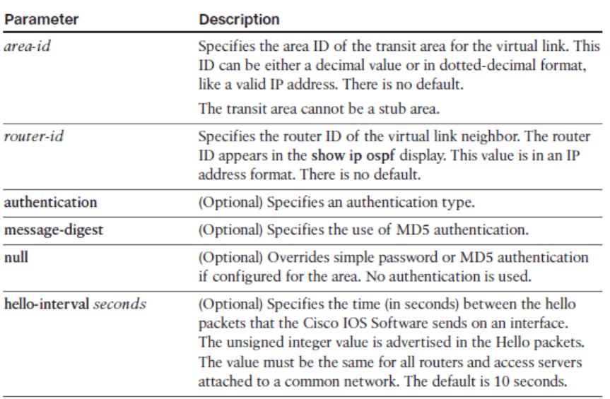
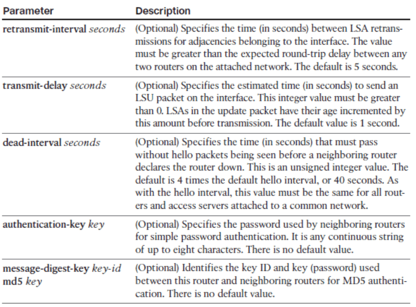
area area-id virtual-link router-id [ authentication [ message-digest | null ]][ hello-interval seconds ] [ retransmit-interval seconds ] [ transmitdelay seconds ] [ dead-interval seconds ] [[ authentication-key
key ] | [ message-digest-key key-id md5 key ]]
OSPF Stub Areas
The stub and totally stubby areas are deployed to reduce the size of the OSPF database and routing table:
Stub area: This area type does not accept information about routes external to the autonomous system, such as routes from non-OSPF sources. If routers need to route to networks outside the autonomous system, they use a default route, indicated as 0.0.0.0. Stub areas cannot contain ASBRs (except that the ABRs may also be ASBRs). The stub area does not accept external routes.
Totally stubby area: This Cisco proprietary area type does not accept external autonomous system routes or summary routes from other areas internal to the autonomous system. If a router needs to send a packet to a network external to the area, it sends the packet using a default route. Totally stubby areas cannot contain ASBRs (except that the ABRs may also be ASBRs). A totally stubby area does not accept external or interarea routes.
Configuring OSPF Stub Areas
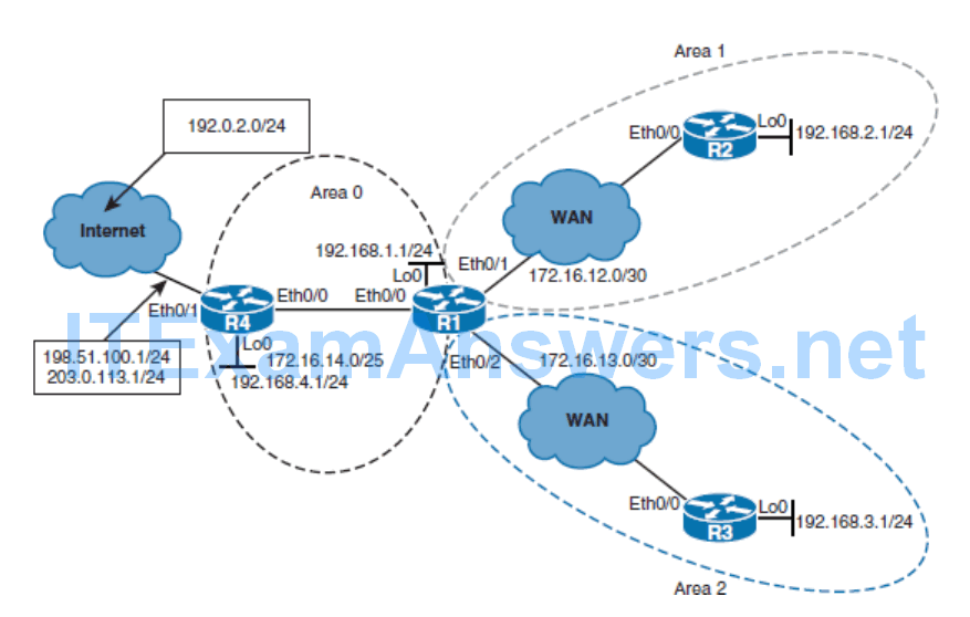
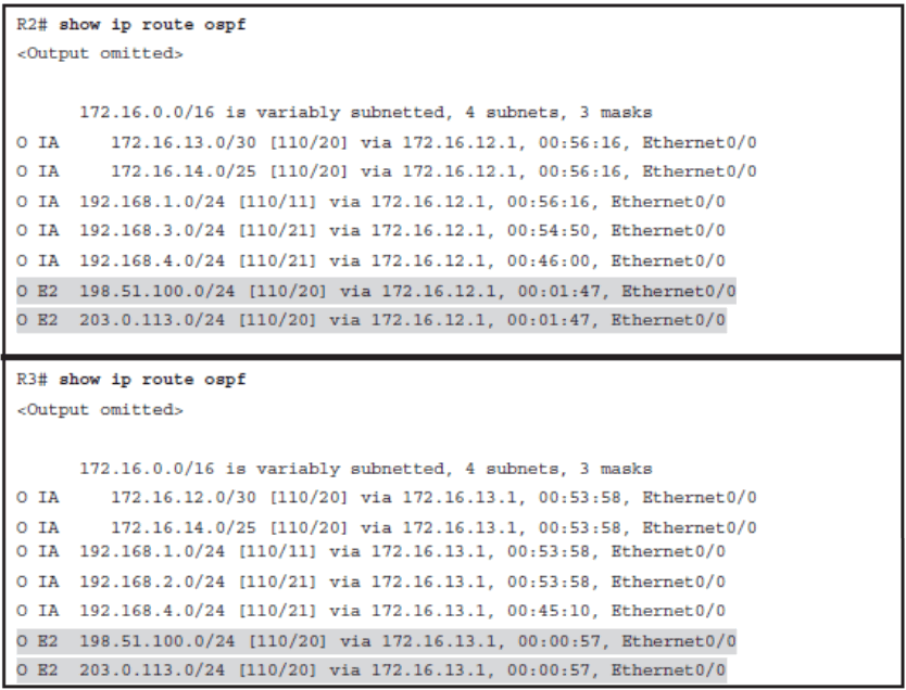

- Configuring a stub area reduces the size of the LSDB inside the area, resulting in reduced memory requirements for routers in that area. External network LSAs (type 5), such as those that are redistributed from other routing protocols into OSPF, are not permitted to flood into a stub area.
- The area stub router configuration mode command is used to define an area as a stub area. Each router in the stub area must be configured with the area stub command. The
- Hello packets that are exchanged between OSPF routers contain a stub area flag that must match on neighboring routers. Until the area 1 stub command is enabled on R2 in this scenario, the adjacency between R1 and R2 will be down.
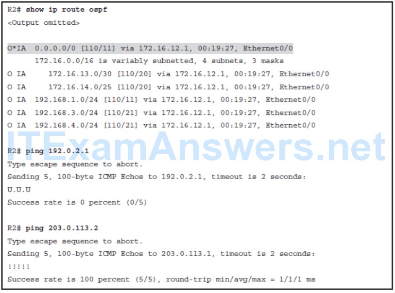
Propagating a Default Route Using OSPF

OSPF Totally Stubby Areas

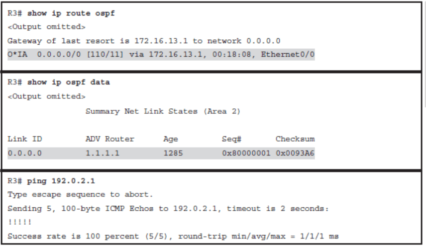
The leaf router (R3) in the totally stubby area has the smallest possible routing table. Only the intra-area routes are maintained. Interarea and external routes are not visible in the routing tables for each stub area, but are accessible via the intra-area default routes for that stub area.
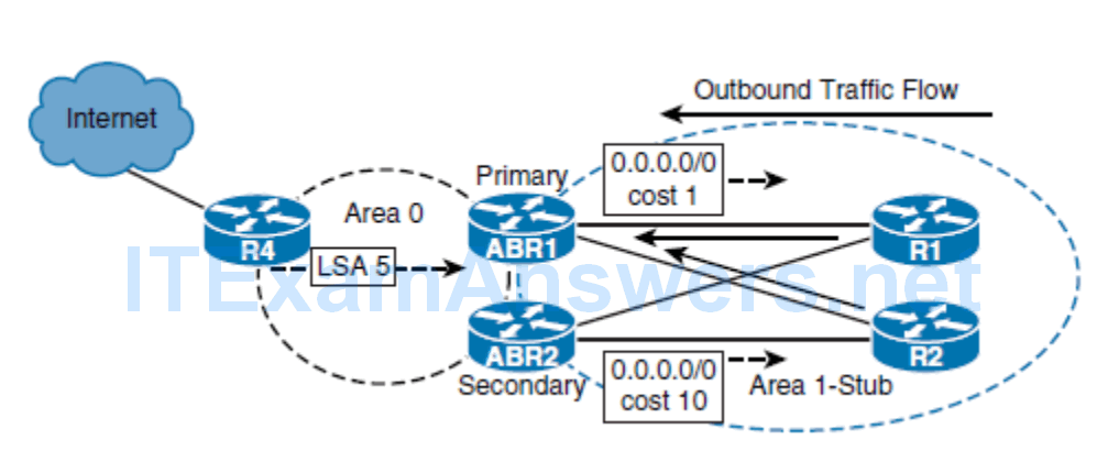
Cost of the Default Route in a Stub Area
- By default, the ABR of a stub area will advertise a default route with a cost of 1.
- You can change the cost of the default route by using the area default-cost command.
- The default-cost option provides the metric for the summary default route that is generated by the ABR into the stub area.
- area area-id default-cost cost

- The option of tuning the cost of the default route in the stub area is useful in stub areas with redundant exit points to the backbone area
The default-information originate Command
default-information originate [ always ] [ metric metric-value ] [ metric-type typevalue ] [ route-map map-name ]
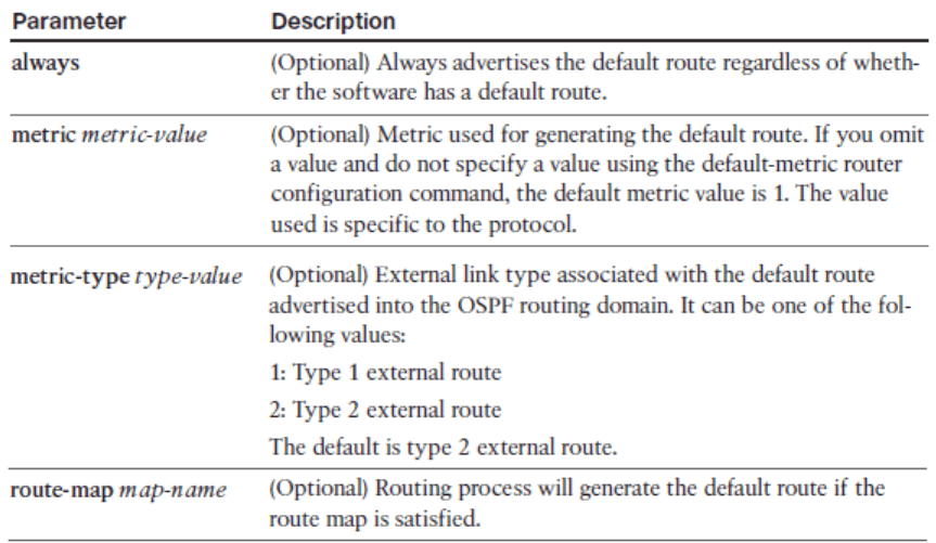
- There are two ways to advertise a default route into a standard area. You can advertise 0.0.0.0/0 into the OSPF domain when the advertising router already has a default route.
- Use the default-information originate command to allow the ASBR to originate a type 5 default route inside the OSPF autonomous system. The default route must be in the routing table otherwise it will not be propagated by OSPF.
- You can use different keywords in the configuration command to configure dependency on IP routing table entries. To advertise 0.0.0.0/0 regardless of whether the advertising router already has a default route, add the keyword always to the default-information originate command. The default route will be propagated by OSPF whether or not there is a default route.
- Whenever you use the redistribute or the default-information command to redistribute routes into an OSPF routing domain, the router automatically becomes an ASBR. You can also use a route map to define dependency on any condition inside the route map. The metric and metric-type options allow you to specify the OSPF cost and metric type of the injected external route.
Other Stubby Area Types
- The NSSA is a nonproprietary extension of the existing stub area feature that allows the injection of external routes in a limited fashion into the stub area.

- The area nssa router configuration mode command is used to define each router in the NSSA area as not-so-stubby
- The area nssa command with the no-summary keyword is used to define the ABR as totally not-so-stubby.
OSPFv3
- Implement OSPFv3 in a dual-stack (IPv4/IPv6) environment
- Configure external route summarization and load balancing in OSPFv3
- Explain the limitations and where you need to be careful when configuring OSPFv3
Configuring OSPFv3
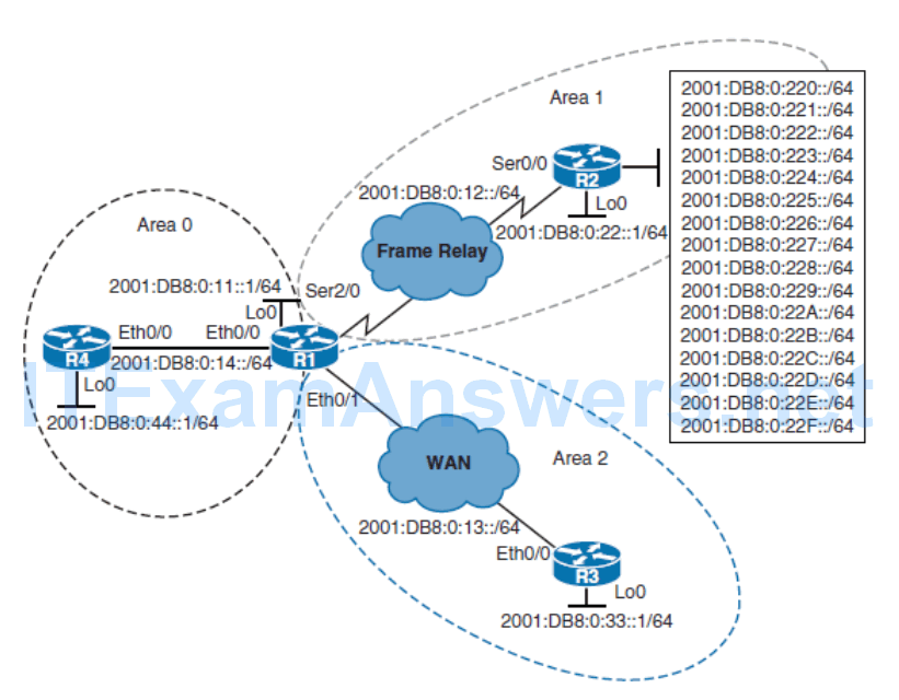
- Cisco IOS routers offer two OSPF configuration methods for IPv6:
- Using the traditional ipv6 router ospf global configuration command
- Using the new-style router ospfv3 global configuration command
- OSPFv3 is the IPv6-capable version of the OSPF routing protocol. It is a rewrite of the OSPF protocol to support IPv6, although the foundation remains the same as in IPv4 and OSPFv2.
- The OSPFv3 metric is still based on interface cost.
- The packet types and neighbor discovery mechanisms are the same in OSPFv3 as they are for OSPFv2.
- OSPFv3 also supports the same interface types, including broadcast, point-to-point, point-tomultipoint,
- NBMA, and virtual links.
- LSAs are still flooded throughout an OSPF domain, and many of the LSA types are the same, though a few have been renamed or newly created.
Enabling OSPFv3
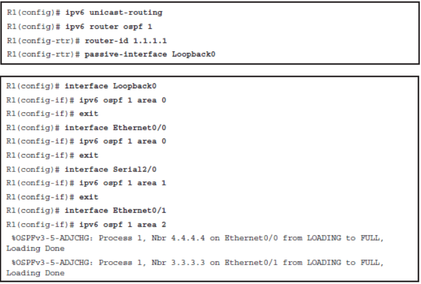
- The OSPF process for IPv6 does not require an IPv4 address to be configured on the router, but it does require a 32-bit value for the router ID, which uses IPv4 address notation.
- The router ID is defined using the router-id command. If the router ID is not specifically configured, the system will try to dynamically choose an ID from the currently active IPv4 addresses, using the same process as OSPFv2 does for IPv4. If there is no active IPv4 address, the process will fail to start.
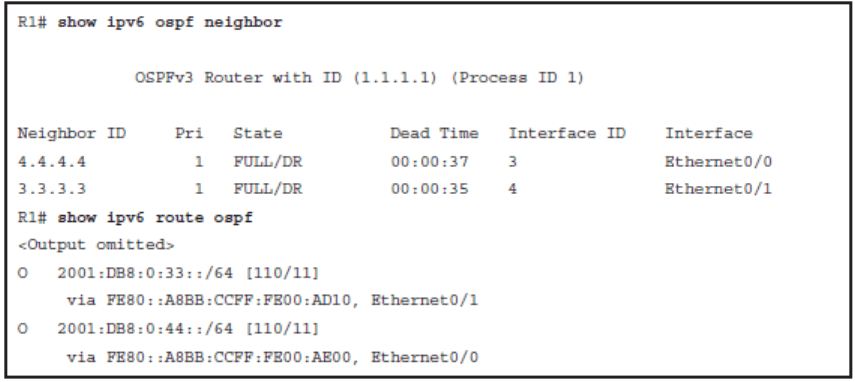
OSPFv3 Adjacencies and Routing Table
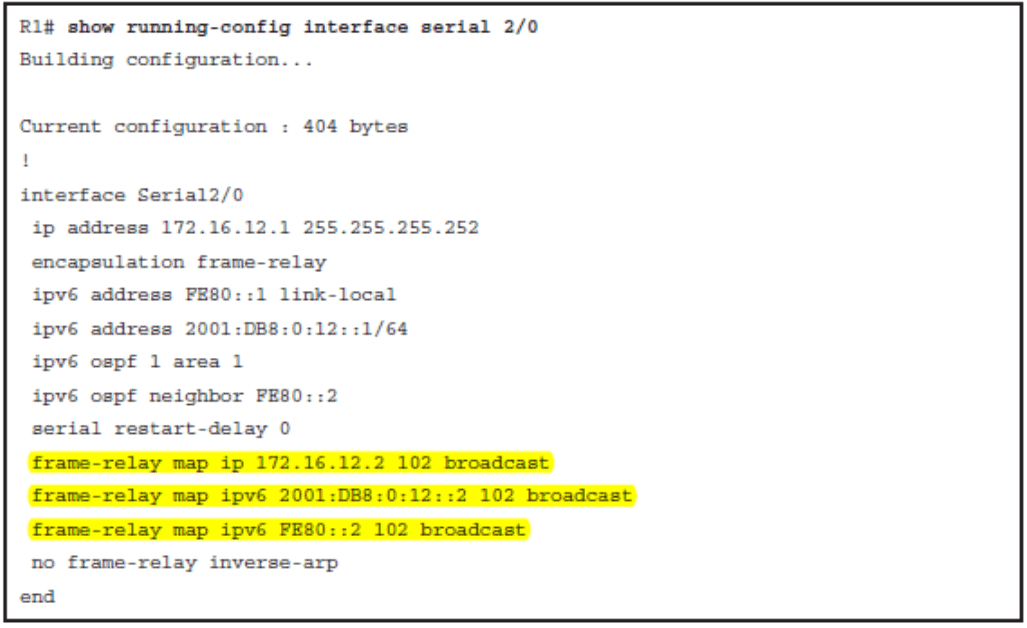
Specifying the Neighbor on an NBMA Interface
OSPF adjacencies over NBMA links require that IPv6 connectivity for both the link-local and the global addresses is established. Depending on the transport network, this may require mapping of IPv6 addresses to Layer 2 circuit identifiers

OSPFv3 LSDB
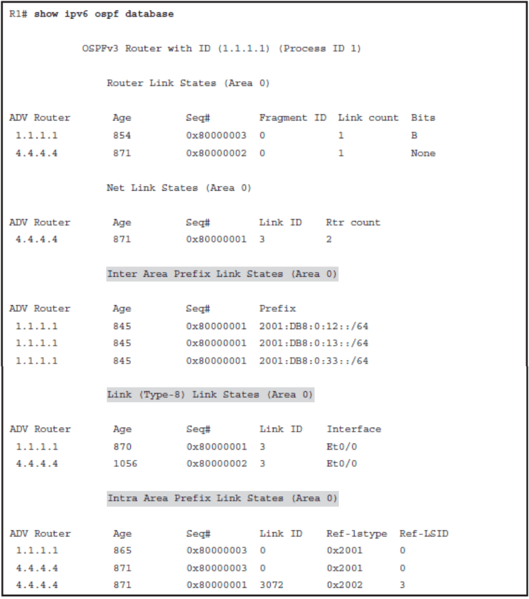
Renamed LSA
- Interarea prefix LSAs for ABRs (Type 3): Type 3 LSAs advertise internal networks to routers in other areas (interarea routes). Type 3 LSAs may represent a single network or a set of networks summarized into one advertisement. Only ABRs generate summary LSAs. In OSPF for IPv6, addresses for these LSAs are expressed as prefix/ prefix length instead of address and mask. The default route is expressed as a prefix with length 0.
- Interarea router LSAs for ASBRs (Type 4): Type 4 LSAs advertise the location of an ASBR. Routers that are trying to reach an external network use these advertisements to determine the best path to the next hop. ASBRs generate Type 4 LSAs.
New LSA
- Link LSAs (Type 8): Type 8 LSAs have local-link flooding scope and are never flooded beyond the link with which they are associated. Link LSAs provide the link-local address of the router to all other routers attached to the link. They inform other routers attached to the link of a list of IPv6 prefixes to associate with the link. In addition, they allow the router to assert a collection of option bits to associate with the network LSA that will be originated for the link.
- Intra-area prefix LSAs (Type 9): A router can originate multiple intra-area prefix LSAs for each router or transit network, each with a unique link-state ID. The linkstate ID for each intra-area prefix LSA describes its association to either the router LSA or the network LSA. The link-state ID also contains prefixes for stub and transit networks.
OSPFv3 for IPv4 and IPv6
- The newest OSPFv3 configuration approach utilizes a single OSPFv3 process.
- It is capable of supporting IPv4 and IPv6 within a single OSPFv3 process.
- OSPFv3 builds a single database with LSAs that carry IPv4 and IPv6 information.
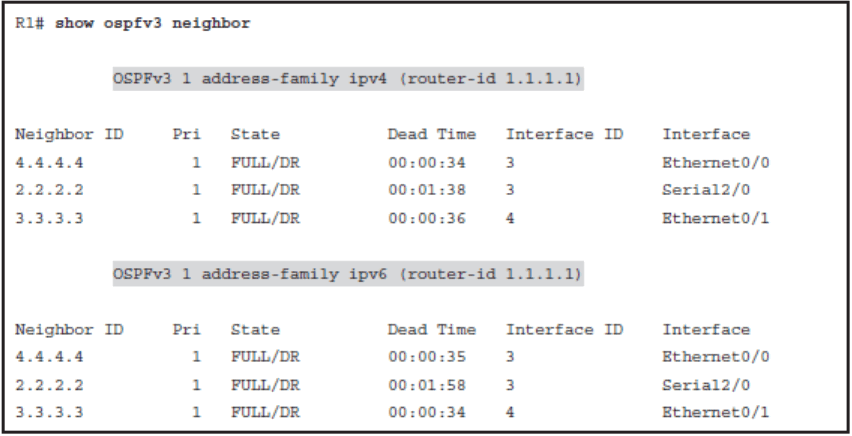
- The OSPF adjacencies are established separately for each address family.
- Settings that are specific to an address family (IPv4/IPv6) are configured inside that address family router configuration mode.
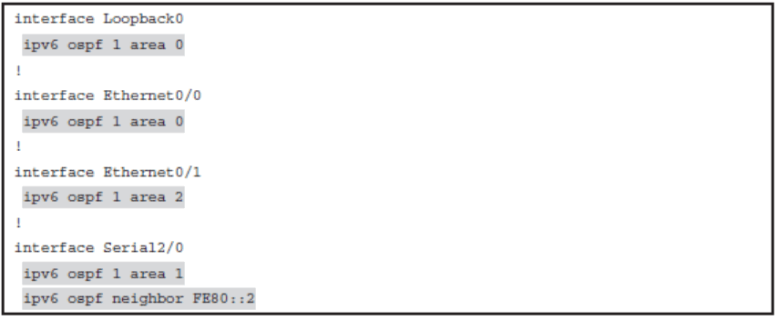
Configuring OSPFv3 Using the router ospfv3
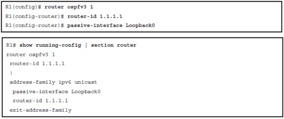
- The address-family ipv6 unicast has been automatically created on R1. Cisco IOS Software has parsed the previous old-style OSPFv3 configuration and found that the OSPF process was enabled only for IPv6.
- The router ID is displayed in the router configuration mode that is valid globally for all address families.
- The address-family ipv6 unicast has been automatically created on R1. Cisco IOS Software has parsed the previous old-style OSPFv3 configuration and found that the OSPF process was enabled only for IPv6.
- Consequently, when you chose the new-style configuration, the IPv6 address family has been instantiated and the IPv4 address family does not show in the configuration.
- The passive-interface configuration is actually a setting that is valid per address family.
- You can have dissimilar settings for IPv4 and IPv6. Therefore this command has been placed in the address family submode.
OSPFv3 Old-Style OSPF Configuration Commands
OSPFv3 New-Style OSPF Configuration Commands
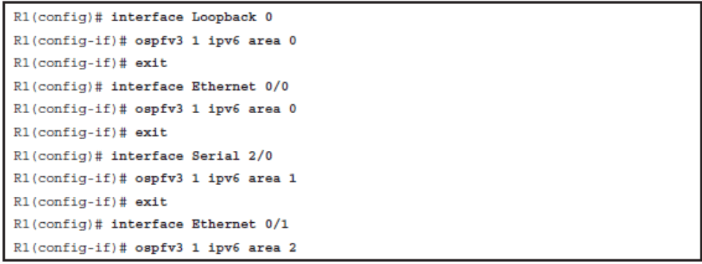
- The preferred interface mode command for the new style OSPFv3 configuration is the ospfv3 process-id {ipv4|ipv6} area area-id command.
- It allows you to selectively activate the OSPFv3 process for an address family (IPv4 or IPv6) on a given interface.
- With the OSPFv3 address families feature, you may have two device processes per interface, but only one process per AF. If the IPv4 AF is used, an IPv4 address must first be configured on the interface. For IPv6 AF it is enough, if only IPv6 is enabled on the interface, as OSPFv3 uses link-local addresses. A single IPv4 or IPv6 OSPFv3 process running multiple instances on the same interface is not supported.
Enabling OSPFv3 for IPv4
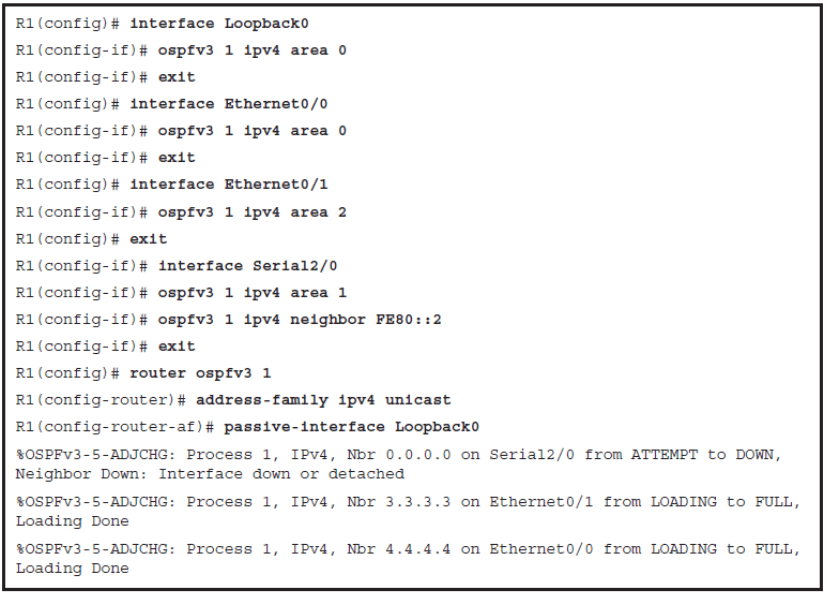
On the NBMA links, such as the interface Serial 2/0 in this scenario, you need to define the OSPF neighbor. In the new-style OSPFv3 you must configure the IPv6 link-local address of the peer as the OSPF neighbor. Both address families use IPv6 as the underlying transport.
OSPFv3 Adjacencies for Both IPv4 and IPv6 Address Families
OSPFv3 LSDB
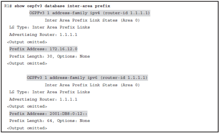
A router maintains a single OSPFv3 database, which contains various LSAs. Some LSAs carry IPv4-related information, others carry IPv6-related information, and others carry mixed information.
IPv4 Routing Table with OSPFv3 Routes

The OSPFv3 database for R1 is examined in Example 3-83
OSPFv3 ipv6 Routing Table
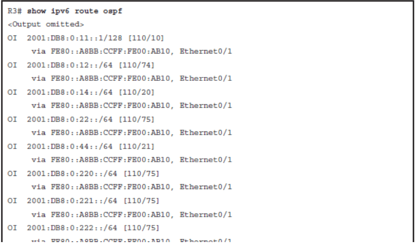
Configuring OSPFv3
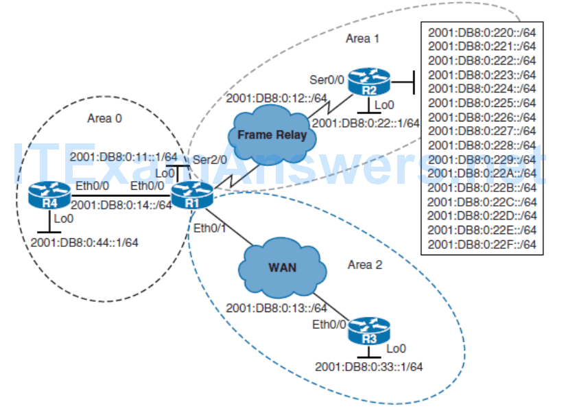
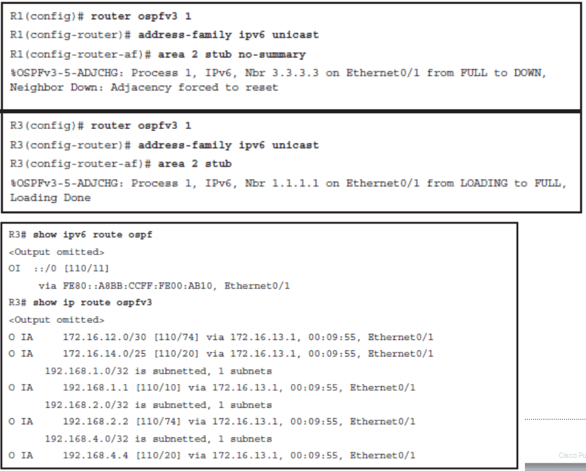
Area 2 Routers Configured as a Totally Stubby Area
OSPFv3 Summarization
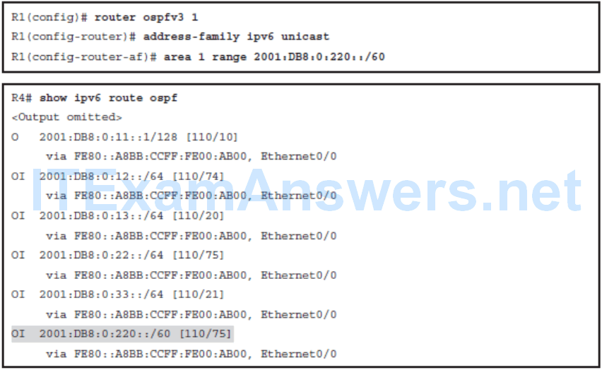
Configuring Advanced OSPFv3
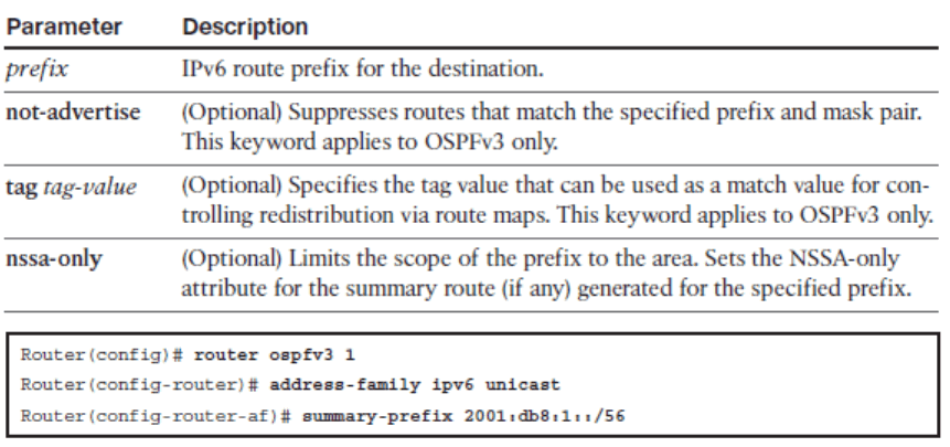
Configuring the summary-prefix Command on an ASBR
summary-prefix prefix [ not-advertise | tag tag-value ] [ nssa-only ]
OSPFv3 Caveats
- The OSPFv3 address families feature is supported as of Cisco IOS Release 15.1(3)S and Cisco IOS Release 15.2(1)T.
- Cisco devices that run software older than these releases and third-party devices will not form neighbor relationships with devices running the address family feature for the IPv4 address family because they do not set the address family bit.
- Therefore, those devices will not participate in the IPv4 address family SPF calculations and will not install the IPv4 OSPFv3 routes in the IPv6 Routing Information Base (RIB).
Chapter 3 Summary
- OSPF uses a two-layer hierarchical approach dividing networks into a backbone area (area 0) and nonbackbone areas.
- For its operation, OSPF uses five packet types: Hello, DBD, LSR, LSU, and LSAck.
- OSPF neighbors go through several different neighbor states before adjacency results in Full state.
- OSPF elects DR/BDR routers on a multiaccess segment to optimize exchange of information.
- The most common OSPF network types are point-to-point, broadcast, nonbroadcast, and loopback.
- OSPF uses several different LSA types to describe the network topology.
- LSAs are stored in an LSDB, which is synchronized with every network change.
- OSPF calculates interface costs based on default reference bandwidth and interface bandwidth.
- Using SPF, OSPF determines the total lowest cost paths and selects them as the best routes.
- Intra-area routes are always preferred over interarea routes.
- Route summarization improves CPU utilization, reduces LSA flooding, and reduces routing table sizes.
- The area range command is used summarize at the ABR. The summary-address command is sued to summarize at the ASBR.
- Default routes can be used in OSPF to prevent the need for specific route to each destination network.
- OSPF uses the default-information originate command to inject a default route.
- There are several OSPF area types: normal, backbone, stub, totally stubby, NSSA, and totally stubby NSSA.
- Use the area area-id command to define an area as stubby.
- Use the area area-id stub command with the no-summary keyword only on the ABR to define an area as totally stubby.
- For stub areas, external routes are not visible in the routing table, but are accessible via the intra-area default route.
- For totally stubby areas, interarea and external routes are not visible in the routing table, but are accessible via the intra-area default route.
- OSPFv3 for IPv6 supports the same basic mechanisms that OSPFv2 for IPv4, including the use of areas to provide network segmentation and LSAs to exchange routing updates.
- OSPFv3 features two new LSA types and has renamed two traditional LSA types.
- OSPFv3 uses link-local addresses to source LSAs.
- OSPFv3 is enabled per-interface on Cisco routers.
- New-style OSPFv3 and traditional OSPFv3 for IPv6, configured with ipv6 router ospf , can coexist in the network to provide IPv6 routing.
