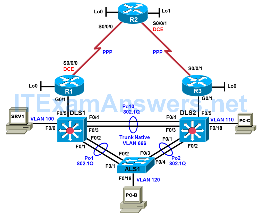
Physical Topology

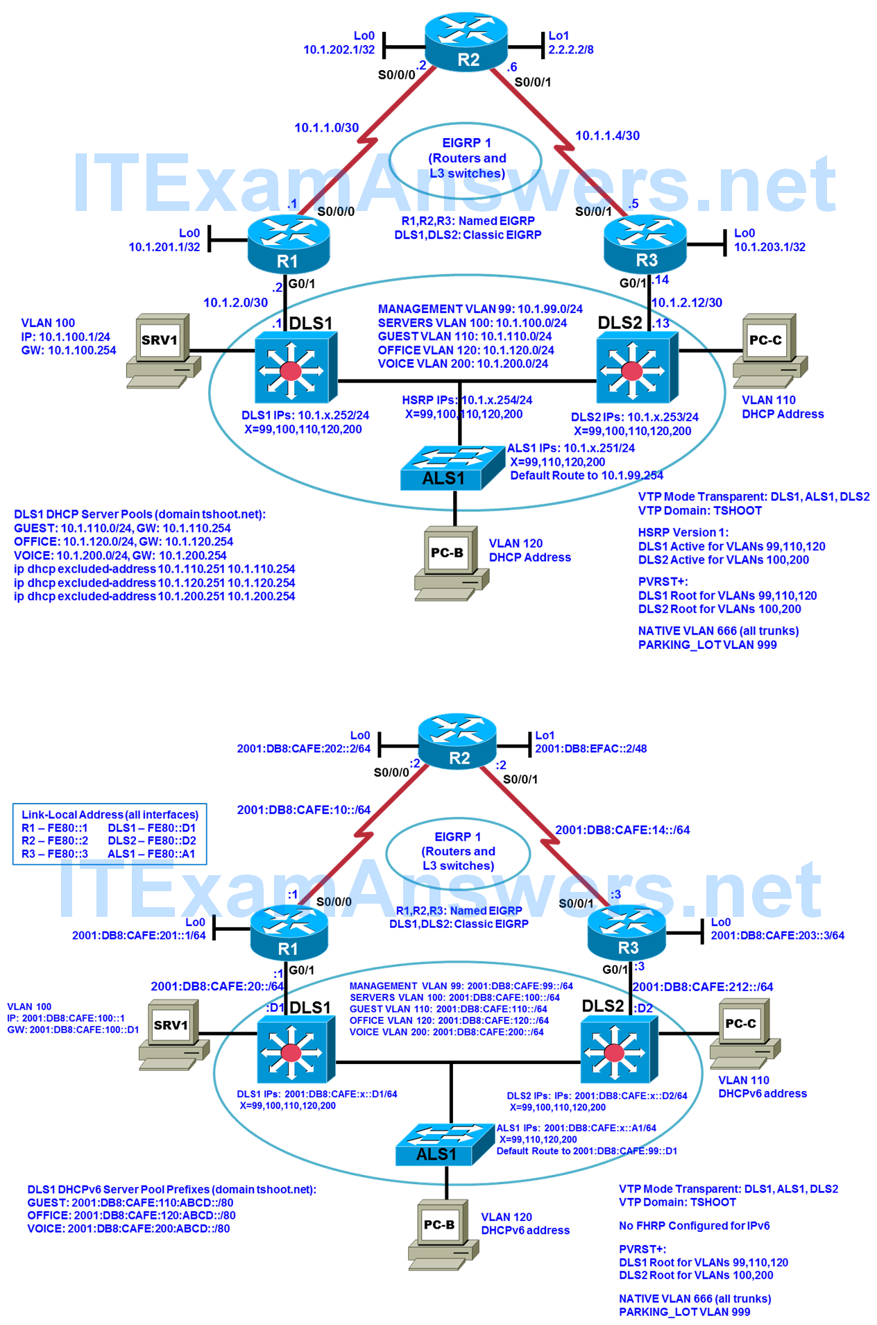
Logical Topology

Objectives
- Load the trouble ticket device configuration files for each trouble ticket.
- Diagnose and resolve problems related to the OSPF routing protocol.
- Diagnose and resolve problems related to route redistribution.
- Document troubleshooting progress, configuration changes, and problem resolution.
Background
In this lab, you troubleshoot various problems related to the Open Shortest Path First (OSPF) routing protocol and route redistribution between routing protocols. For each task or trouble ticket, the trouble scenario and problem symptom are described. While troubleshooting, you will discover the cause of the problem, correct it, and then document the process and results.
Migrating from EIGRP to OSPF
Your company has decided to migrate from using Enhanced Interior Gateway Protocol (EIGRP) to OSPF as the routing protocol. This migration will be executed in two phases.
The engineering team planned and designed the migration, but the support team must support the new network, so they are involved in migrating the branch during Phase 2.
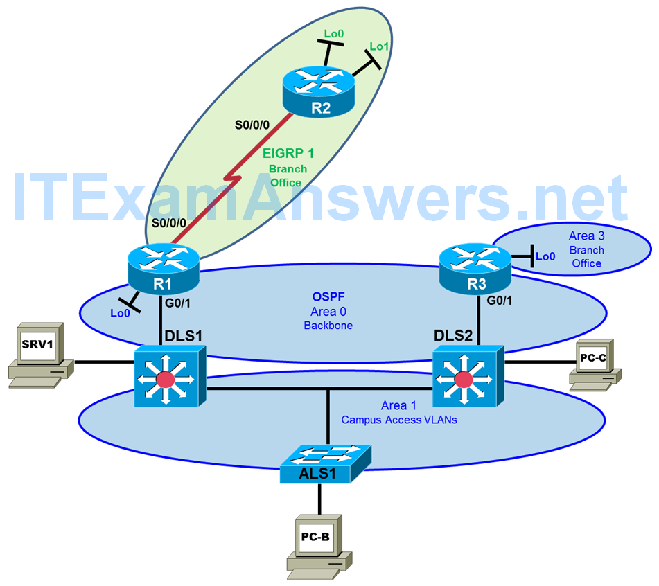
Phase 1 – The headquarters central site campus is migrated to OSPF as well as one of the branch offices (simulated by Lo0 on R3). EIGRP is still used on the WAN toward the R2 branch office. On router R1, redistribution is configured between OSPF and EIGRP to ensure connectivity between headquarters and the branch office connected to R2.
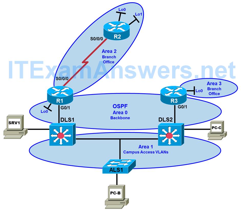
Phase 2 – The R2 branch office (simulated by Lo0 on R2) is converted from EIGRP to OSPF, and all branch offices are migrated so that OSPF is used in the entire network. Each branch site will be in a separate totally stub area.
Today is Saturday, and the engineering team has been busy implementing OSPF and removing EIGRP at the headquarters site. Although you have not taken part in the actual implementation, some of the senior engineers in the support team are on standby to assist during the verification and troubleshooting phase. Together with the engineering team, you will have to make the decision on Sunday to either accept the implementation or, if major issues are uncovered that would threaten the stability of the network, roll back to the original configurations.
OSPF Network Design
Phases 1 and 2 of the OSPF design are depicted in the following figures. Backbone Area 0 contains the FastEthernet interfaces on core Layer 3 switches DLS1 and DLS2 as well as the GigabitEthernet interfaces on routers R1 and R3. Area 0 also includes VLAN 300 and the corresponding SVI, which have been added to these two switches so that they can form an OSPF neighbor relationship and exchange routes. The headquarters campus access VLANs 100, 110, 120, and 200 and management VLAN 99 are in OSPF Area 1. The R2 stub network is in Area 2, and the R3 stub network is in Area 3.
Phase 1 OSPF Network Design

Phase 2 OSPF Network Design

Test Plan
To test the branch connectivity using redistribution between EIGRP and OSPF and the eventual conversion to only OSPF, branch routers R2 and R3 have been specifically prepared for both of these scenarios. Router R2 functions as the default gateway for the R2 LAN, while router R3 is the default gateway for the R3 LAN. Router R2 runs EIGRP as usual. This allows testing the redistribution of EIGRP from the R2 branch office LAN (simulated by R2 Lo0) to OSPF Area 0 and redistribution of OSPF into EIGRP using router R1 as an Autonomous System Border Router (ASBR). Router R3 is configured to run OSPF as an Area Border Router (ABR) between Area 0 and Area 3. The R3 branch office client is simulated by R3 Lo0.
After the completion of Phase 2, all routers except R2 should have OSPF routes. Area 2 is a totally stub area and R2 should only have a default route to R1.
Note: Trouble ticket TT-A is related to the verification and acceptance of Phase 1 of the OSPF migration. Trouble tickets TT-B, C and D are related to the verification and acceptance of Phase 2 of the OSPF migration. Any interfaces that have been shut down on routers R2 and R3 should remain shut down for the duration of this lab exercise.
Physical and Logical Topology Diagrams
The physical and logical topologies for the BASE Lab (First Baseline), with EIGRP, are provided to assist the troubleshooting effort.
Note: This lab uses Cisco ISR G2 routers running Cisco IOS 15.4(3) images with IP Base and Security packages enabled, and Cisco Catalyst 3560 and 2960 switches running Cisco IOS 15.0(2) IP Services and LAN Base images, respectively. The 3560 and 2960 switches are configured with the SDM templates dual-ipv4-and-ipv6 routing and lanbase-routing, respectively. Depending on the router or switch model and Cisco IOS Software version, the commands available and output produced might vary from what is shown in this lab. Any changes made to the baseline configurations or topology (other than errors introduced) are noted in the trouble ticket so that you are aware of them prior to beginning the troubleshooting process.
Note: Any changes made to the BASE Lab configurations or topology (other than errors introduced) are noted in the trouble ticket so that you are aware of them prior to beginning the troubleshooting process.
Required Resources
- 3 routers (Cisco IOS Release 15.4 or comparable)
- 2 multilayer switches and 1 access layer switch (Cisco IOS Release 15.0(2) or comparable with Fast Ethernet interfaces)
- SRV1 (PC with static IP address): Windows 7 with RADIUS, TFTP, and syslog servers, plus an SSH client, SNMP monitor, and WireShark software
- PC-B (DHCP client): Windows 7 with SSH client and WireShark software
- PC-C (DHCP client): Windows 7 with SSH client and WireShark software
- Serial and Ethernet cables, as shown in the topology
Task 1: Trouble Ticket Lab 7-1 TT-A
Step 1: Review trouble ticket Lab 7-1 TT-A.
After the completion of Phase 1 – implementation of OSPF in the headquarters portion of the network and the redistribution between EIGRP and OSPF – the connectivity from the office LAN on the R2 branch router to server SRV1 at headquarters is tested. A ping from the R2 LAN client (sourced by Lo0 on R2) to server SRV1 fails.
Your task is to diagnose this problem and, if possible, resolve it. Connectivity from the R2 LAN to server SRV1 is mandatory to consider this phase of the migration successful.
Step 2: Load the device trouble ticket configuration files for TT-A.
Using the procedure described in the BASE Lab, verify that the lab configuration files are present in flash. Load the proper configuration files indicated in the Device Configuration File Table. The files are based on the First Baseline.
Note: You can gain access to the router GUI management interface through a web browser – when prompted enter the username cisco and the enable password cisco.
Device Configuration File Table
| Device Name | File to Load | Notes |
|---|---|---|
| ALS1 | Lab71-ALS1-TT-A-Cfg.txt | |
| DLS1 | Lab71-DLS1-TT-A-Cfg.txt | |
| DLS2 | Lab71-DLS2-TT-A-Cfg.txt | |
| R1 | Lab71-R1-TT-A-Cfg.txt | |
| R2 | Lab71-R2-TT-A-Cfg.txt | |
| R3 | Lab71-R3-TT-A-Cfg.txt | |
| SRV1 | N/A | Static IP: 10.1.100.1 and 2001:DB8:CAFE:100::1 Default gateway: 10.1.100.254/24 and 2001:DB8:CAFE:100::D1/64 |
| PC-B | N/A | DHCPv4 and DHCPv6 |
| PC-C | N/A | DHCPv4 and DHCPv6 |
Step 3: Configure SRV1 and start the syslog and TFTP servers.
Step 4: Release and renew the DHCP lease on PC-B.
Ensure that PC-B is configured as a DHCP client for both IPv4 and IPv6 in the OFFICE VLAN.
After loading all TT-A device configuration files, issue the ipconfig /release and ipconfig /renew commands on PC-B.
Step 5: Outline the troubleshooting approach and validation steps.
Use this space to identify your troubleshooting approach and the key steps to verify that the problem is resolved. Troubleshooting approaches to select from include the follow-the-path, perform-comparison, bottom-up, top-down, divide-and-conquer, shoot-from-the-hip, and swap-components (move-the-problem) methods.
Note: In addition to a specific approach, you can use the generic troubleshooting process: defining a problem, gathering information, analyzing the information, eliminating possible problem causes, formulating a hypothesis about the likely cause of the problem, testing that hypothesis, and solving the problem.
_________________________________________________________________
Step 6: Record the troubleshooting process and configuration changes.
Use this log to document your actions and results during the troubleshooting process. List the commands you used to gather information. As you progress, record your thoughts as to what you think the problem might be and which actions you take to correct the problem.
| Device | Actions and Results |
|---|---|
Step 7: Document trouble ticket debrief notes.
Use this space to make notes of the key learning points that you picked up during the discussion of this trouble ticket with your instructor. The notes can include problems encountered, solutions applied, and useful commands employed. It can also include alternate solutions, methods, and procedures and communication improvements.
________________________________________________________________
Task 2: Trouble Ticket Lab 7-1 TT-B
Step 1: Review trouble ticket Lab 7-1 TT-B.
Phase 2 has been completed and all routers have been converted to OSPF. The connectivity from a branch office client on the R2 LAN (simulated by R2 Lo0) to server SRV1 at the central site is tested. A ping from the client on the R2 LAN (using source interface Lo0) to server SRV1 fails. The connectivity problem is not limited to SRV1. An attempt to connect to other headquarters servers also fails. Your task is to diagnose this problem and, if possible, resolve it. Connectivity from the branch client to server SRV1 is mandatory for this phase of the migration to be considered successful.
Note: Refer back to the implementation and test plan to review the requirements for Phase 2.
Step 2: Load the device trouble ticket configuration files for TT-B.
Using the procedure described in the BASE Lab, verify that the lab configuration files are present in flash. Load the proper configuration files indicated in the Device Configuration File Table. The files are based on the First Baseline.
Device Configuration File Table
| Device Name | File to Load | Notes |
|---|---|---|
| ALS1 | Lab71-ALS1-TT-B-Cfg.txt | |
| DLS1 | Lab71-DLS1-TT-B-Cfg.txt | |
| DLS2 | Lab71-DLS2-TT-B-Cfg.txt | |
| R1 | Lab71-R1-TT-B-Cfg.txt | |
| R2 | Lab71-R2-TT-B-Cfg.txt | |
| R3 | Lab71-R3-TT-B-Cfg.txt | |
| SRV1 | N/A | Static IP: 10.1.100.1 and 2001:DB8:CAFE:100::1 Default gateway: 10.1.100.254/24 and 2001:DB8:CAFE:100::D1/64 |
| PC-B | N/A | DHCPv4 and DHCPv6 |
| PC-C | N/A | DHCPv4 and DHCPv6 |
Step 3: Configure SRV1 and start the syslog and TFTP servers.
Step 4: Release and renew the DHCP leases on PC-B and PC-C.
Step 5: Outline the troubleshooting approach and validation steps.
Use this space to identify your troubleshooting approach and the key steps to verify that the problem is resolved. Troubleshooting approaches to select from include the follow-the-path, perform-comparison, bottom-up, top-down, divide-and-conquer, shoot-from-the-hip, and swap-components (move-the-problem) methods.
Note: In addition to a specific approach, you can use the generic troubleshooting process: defining a problem, gathering information, analyzing the information, eliminating possible problem causes, formulating a hypothesis about the likely cause of the problem, testing that hypothesis, and solving the problem.
___________________________________________________________________
Step 6: Record the troubleshooting process and configuration changes.
Use this log to document your actions and results during the troubleshooting process. List the commands you used to gather information. As you progress, record your thoughts as to what you think the problem might be and which actions you take to correct the problem.
| Device | Actions and Results |
|---|---|
Step 7: Document trouble ticket debrief notes.
Use this space to make notes of the key learning points that you picked up during the discussion of this trouble ticket with your instructor. The notes can include problems encountered, solutions applied, useful commands employed, alternate solutions, methods and procedure, and procedure and communication improvements.
_____________________________________________________________________
Task 3: Trouble Ticket Lab 7-1 TT-C
Step 1: Review trouble ticket Lab 5-2 TT-C.
After implementing OSPF, connectivity from the branch office on R3 (simulated by Lo0) to SRV1 is not working. A ping from PC-B to server SRV1 succeeds, but pings from R3 Lo0 to SRV1 fail.
Your task is to diagnose this problem and, if possible, resolve it. Connectivity from R3 branch office clients to server SRV1 is mandatory for this phase of the migration to be considered successful.
Step 2: Load the device trouble ticket configuration files for TT-C.
Using the procedure described in the BASE Lab, verify that the lab configuration files are present in flash. Load the proper configuration files indicated in the Device Configuration File Table. The files are based on the First Baseline.
Device Configuration File Table
| Device Name | File to Load | Notes |
|---|---|---|
| ALS1 | Lab71-ALS1-TT-C-Cfg.txt | |
| DLS1 | Lab71-DLS1-TT-C-Cfg.txt | |
| DLS2 | Lab71-DLS2-TT-C-Cfg.txt | |
| R1 | Lab71-R1-TT-C-Cfg.txt | |
| R2 | Lab71-R2-TT-C-Cfg.txt | |
| R3 | Lab71-R3-TT-C-Cfg.txt | |
| SRV1 | N/A | Static IP: 10.1.100.1 and 2001:DB8:CAFE:100::1 Default gateway: 10.1.100.254/24 and 2001:DB8:CAFE:100::D1/64 |
| PC-B | N/A | DHCPv4 and DHCPv6 |
| PC-C | N/A | DHCPv4 and DHCPv6 |
Step 3: Configure SRV1 and start the syslog and TFTP servers.
Step 4: Release and renew the DHCP leases on PC-B and PC-C.
Step 5: Outline the troubleshooting approach and validation steps.
Use this space to identify your troubleshooting approach and the key steps to verify that the problem is resolved. Troubleshooting approaches to select from include the follow-the-path, perform-comparison, bottom-up, top-down, divide-and-conquer, shoot-from-the-hip, and swap-components (move-the-problem) methods.
Note: In addition to a specific approach, you can use the generic troubleshooting process: defining a problem, gathering information, analyzing the information, eliminating possible problem causes, formulating a hypothesis about the likely cause of the problem, testing that hypothesis, and solving the problem.
__________________________________________________________________
Step 6: Record the troubleshooting process and configuration changes.
Use this log to document your actions and results during the troubleshooting process. List the commands you used to gather information. As you progress, record your thoughts as to what you think the problem might be and which actions you take to correct the problem.
| Device | Actions and Results |
|---|---|
Step 7: Document trouble ticket debrief notes.
Use this space to make notes of the key learning points that you picked up during the discussion of this trouble ticket with your instructor. The notes can include problems encountered, solutions applied, useful commands employed, alternate solutions and methods, and procedure and communication improvements.
____________________________________________________________________
Task 4: Trouble Ticket Lab 7-1 TT-D
Step 1: Review trouble ticket Lab 7-1 TT-D.
A recent security audit suggested that it would be best practice to secure the OSPF implementation by using MD5 authentication between the routers. Because this could complicate the implementation, it was decided that it was too late to include this now for all areas. However, to test the concept, it was decided to enable authentication in Area 0 for two devices. If the test is successful, the authentication will be added to other areas during the second phase of the implementation. If the test is not successful, a separate project will be initiated to implement the authentication.
One of your colleagues has enabled MD5 authentication for Area 0 on VLAN 300, which is the link between the core switches DLS1 and DLS2 in Area 0. Unfortunately, the neighbor relationship between DLS1 and DLS2 on VLAN 300 is not established.
Your task is to diagnose this problem and, if possible, resolve it. After correcting the OSPF neighbor relationship, verify that OSPF authentication between DLS1 and DLS2 is functioning correctly. You may disable the password encryption service during authentication testing.
Step 2: Load the device trouble ticket configuration files for TT-D.
Using the procedure described in the BASE Lab, verify that the lab configuration files are present in flash. Load the proper configuration files indicated in the Device Configuration File Table. The files are based on the First Baseline.
Device Configuration File Table
| Device Name | File to Load | Notes |
|---|---|---|
| ALS1 | Lab71-ALS1-TT-D-Cfg.txt | |
| DLS1 | Lab71-DLS1-TT-D-Cfg.txt | |
| DLS2 | Lab71-DLS2-TT-D-Cfg.txt | |
| R1 | Lab71-R1-TT-D-Cfg.txt | |
| R2 | Lab71-R2-TT-D-Cfg.txt | |
| R3 | Lab71-R3-TT-D-Cfg.txt | |
| SRV1 | N/A | Static IP: 10.1.100.1 and 2001:DB8:CAFE:100::1 Default gateway: 10.1.100.254/24 and 2001:DB8:CAFE:100::D1/64 |
| PC-B | N/A | DHCPv4 and DHCPv6 |
| PC-C | N/A | DHCPv4 and DHCPv6 |
Step 3: Configure SRV1 and start the syslog and TFTP servers.
Step 4: Release and renew the DHCP leases on PC-B and PC-C.
Step 5: Outline the troubleshooting approach and validation steps.
Use this space to identify your troubleshooting approach and the key steps to verify that the problem is resolved. Troubleshooting approaches to select from include the follow-the-path, perform-comparison, bottom-up, top-down, divide-and-conquer, shoot-from-the-hip, and swap-components (move-the-problem) methods.
Note: In addition to a specific approach, you can use the generic troubleshooting process: defining a problem, gathering information, analyzing the information, eliminating possible problem causes, formulating a hypothesis about the likely cause of the problem, testing that hypothesis, and solving the problem.
___________________________________________________________________
Step 6: Record the troubleshooting process and configuration changes.
Use this log to document your actions and results during the troubleshooting process. List the commands you used to gather information. As you progress, record your thoughts as to what you think the problem might be and which actions you take to correct the problem.
| Device | Actions and Results |
|---|---|
Step 7: Document trouble ticket debrief notes.
Use this space to make notes of the key learning points that you picked up during the discussion of this trouble ticket with your instructor. The notes can include problems encountered, solutions applied, useful commands employed, alternate solutions and methods, and procedure and communication improvements.
___________________________________________________________________
