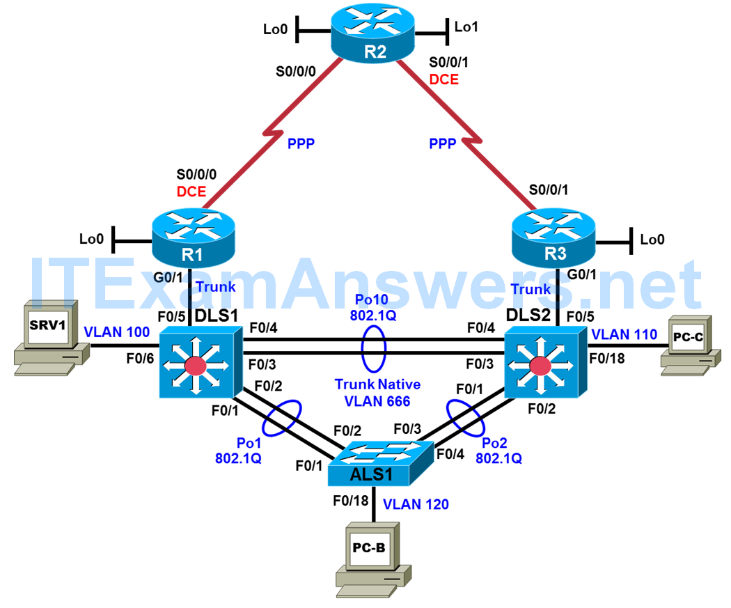
Physical Topology (First Base)

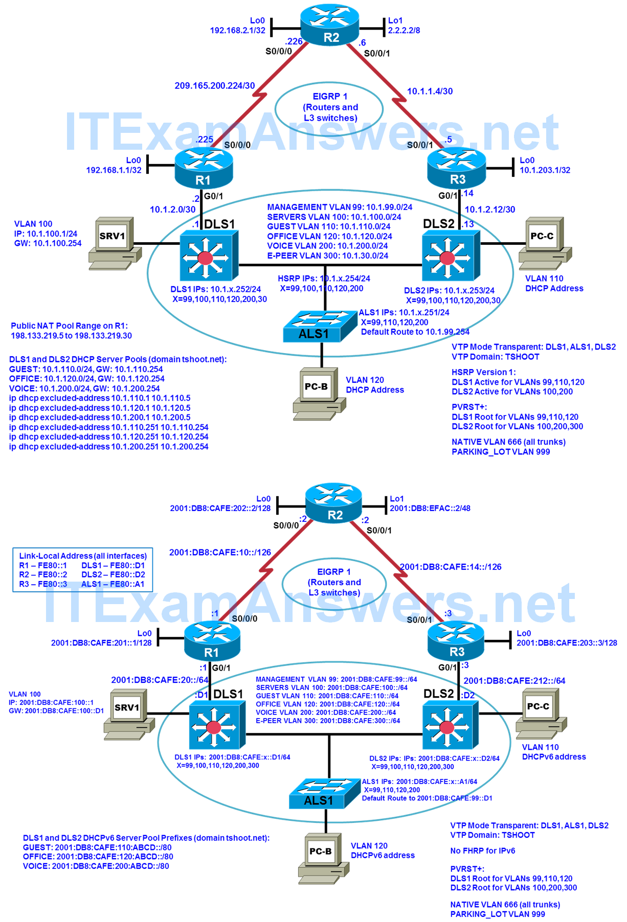
Logical Topology (First Base)
Note: Changes from First Base: Lo0 address changes on R1 and R2, R1-R2 serial link IPv4 addressing changes, /126 on serial links for IPv6, /128 on some loopbacks for IPv6, DHCP shared between DLS1 and DLS2 (with address spaces separated for IPv4), DLS1-DLS2 EIGRP peering only on new VLAN 300, and NAT on R1.

Objectives
- Load the trouble ticket device configuration files for each trouble ticket.
- Diagnose and resolve problems related to the BGP exterior routing protocol.
- Document troubleshooting progress, configuration changes, and problem resolution.
Background
Border Gateway Protocol (BGP) is the most widely used exterior routing protocol on the Internet. It is the de facto standard for route (prefix) exchange between the autonomous systems (AS) of Internet service providers (ISPs). BGP can also be used between a customer network and one or more ISPs. In this lab, you will troubleshoot various problems related to BGP. For each task or trouble ticket, the trouble scenario and problem symptom are described. While troubleshooting, you will discover the cause of the problem, correct it, and then document the process and results.
Implementing BGP
Your company has decided to implement several new Internet-based services. The current web services that the company offers are hosted at an external data center. It has been decided to build an in-house data center from which the new services will be hosted. The servers that are currently externally hosted will also be moved to the new data center.
Your company currently has a single ISP for Internet access. You have obtained a registered AS number (65501) and address block 172.30.1.0/27 for IPv4 and 2001:DB8:CAFE:130::/64 for IPv6, which will be used for the new services. After consulting with the ISP, it has been decided to use BGP between the network edge router R1 and the ISP (R2). Upon successful completion of the BGP implementation, your company is considering adding another ISP for redundancy, but not as part of the current project.
Your support team has been working closely together with the engineering team to prepare the implementation. You have received confirmation from the ISP that they have prepared their router for the BGP implementation.
Router R1 will advertise the IPv4 and IPv6 address blocks to the ISP (R2). No other prefixes are allowed to be advertised. This ensures that only the assigned network address block will be received by the ISP. ISPs typically place filters on their edge routers to prevent customers from accidently announcing routes that do not belong to them.
The ISP router will send a default route to router R1 via BGP. The default route will be redistributed into EIGRP by router R1. No other routes will be redistributed.
It is Friday evening, and the engineering team has just configured router R1 for BGP. To facilitate testing, a new hosted services VLAN and the corresponding IPv4 and IPv6 subnets will be created. All other IPv4 devices, which have addresses in the 10.1.0.0/16 range, are using Network Address Translation (NAT), and their Internet access should not be affected by the BGP configuration.
You are on standby to assist in troubleshooting and testing the solution.
Implementation Plan
The implementation plan is in two phases. The plan describes mostly IPv4, but IPv6 configurations are included in parallel, with .
Phase 1
During Phase 1, the link between edge router R1 and the existing ISP will be converted to BGP. The remainder of the network will continue to use EIGRP. The following changes taking place in Phase 1 are already reflected in the logical topology diagram above:
The 10.1.1.0/30 addressing on the R1-to-R2 serial WAN link will be changed to a public address (209.165.200.224/30) provided by the ISP. NAT will overload the 10.1.0.0/16 internal private addresses to public addresses in 198.133/219.0/27. Lo0 on R1 has IP address 192.168.1.1. Lo0 on R2 has IP address 192.168.2.1. The loopbacks on R1 and R2 will be used for external BGP peering via IPv6.
The ISP will advertise a default route to R1 via BGP. IPv6 will be used as the transport protocol for IPv4 and IPv6 BGP routes. On router R1, redistribution of the default route will be configured between BGP and EIGRP to ensure connectivity between headquarters and the ISP.
Phase 2
During Phase 2, the hosted services VLAN 130, named HSVC, and the corresponding subnet 172.30.1.0/27 and 2001:DB8:CAFE:130::/64 will be created on switch DLS1. A test server for the hosted services subnet will be installed, simulated by SVI 130 on DLS1. A static route will be provided from R1 to VLAN 130 via DLS1 SVI 130. Some services will be migrated to the new address block before moving them to the newly built data center.
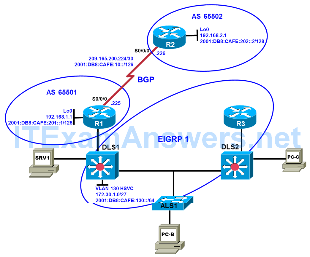
BGP Network Design
The BGP design is outlined in the following figure. BGP AS 65501 is the company’s newly acquired AS number. The ISP AS is 65502.

Test Plan
In Phase 1, edge router R1 must become a BGP peer with the ISP, and the internal office clients must be able to access the Internet through the ISP. In Phase 2, the Internet clients must be able to access the hosted services network.
Note: Trouble ticket A is related to the verification and acceptance of BGP Phase 1. Trouble tickets B and C are related to the second phase of BGP conversion. Any interfaces that have been shut down on routers R2 and R3 should remain shut down for the duration of this lab exercise.
Physical and Logical Topology Diagrams
The physical and logical topologies for the tweaked first baseline are provided at the beginning of this lab to assist the troubleshooting effort.
Note: This lab uses Cisco ISR G2 routers running Cisco IOS 15.4(3) images with IP Base and Security packages enabled, and Cisco Catalyst 3560 and 2960 switches running Cisco IOS 15.0(2) IP Services and LAN Base images, respectively. The 3560 and 2960 switches are configured with the SDM templates dual-ipv4-and-ipv6 routing and lanbase-routing, respectively. Depending on the router or switch model and Cisco IOS Software version, the commands available and output produced might vary from what is shown in this lab. Any changes made to the baseline configurations or topology (other than errors introduced) are noted in the trouble ticket so that you are aware of them prior to beginning the troubleshooting process.
Required Resources
- 3 routers (Cisco IOS Release 15.4 or comparable)
- 2 multilayer switches and 1 access layer switch (Cisco IOS Release 15.0(2) or comparable with Fast Ethernet interfaces)
- SRV1 (PC with static IP address): Windows 7 with RADIUS, TFTP, and syslog servers, plus an SSH client, SNMP monitor, and WireShark software
- PC-B (DHCP client): Windows 7 with SSH client and WireShark software
- PC-C (DHCP client): Windows 7 with SSH client and WireShark software
- Serial and Ethernet cables, as shown in the topology
Task 1: Network Baseline Upgrade Lab 8-2 TT-A
Step 1: Review trouble ticket Lab 8-2 TT-A.
After your colleague finished configuring BGP on edge router R1, you tested connectivity from PC-B in VLAN 120 to the ISP router to verify the configuration and peering between R1 and R2. This test failed. When you asked your colleague, he said he did not actually test the configuration from a client PC on the internal network. He suspected there was a problem with the ISP and contacted them to find out if there was an issue at their end. They stated that everything was correctly configured on router R2.
Your task is to diagnose the problem and verify that BGP is properly configured to enable BGP peering between router R1 and the ISP.
Step 2: Load the device trouble ticket configuration files for TT-A.
Using the procedure described in the BASE Lab, verify that the lab configuration files are present in flash. Load the proper configuration files indicated in the Device Configuration File Table.
Device Configuration File Table
| Device Name | File to Load | Notes |
|---|---|---|
| ALS1 | Lab82-ALS1-TT-A-Cfg.txt | |
| DLS1 | Lab82-DLS1-TT-A-Cfg.txt | |
| DLS2 | Lab82-DLS2-TT-A-Cfg.txt | |
| R1 | Lab82-R1-TT-A-Cfg.txt | |
| R2 | Lab82-R2-TT-A-Cfg.txt | |
| R3 | Lab82-R3-TT-A-Cfg.txt | |
| SRV1 | N/A | Static IP: 10.1.100.1/24 and 2001:DB8:CAFE:100::1/64 Default gateway: 10.1.100.254 and 2001:DB8:CAFE:100::D1 |
| PC-B | N/A | DHCPv4 and DHCPv6 |
| PC-C | N/A | DHCPv4 and DHCPv6 |
Step 3: Configure SRV1 and start the syslog and TFTP servers.
Step 4: Release and renew the DHCP lease on PC-B.
a. Ensure that PC-B is configured as a DHCP client in the OFFICE VLAN.
b. After loading all TT-A device configuration files, issue the ipconfig /release and ipconfig /renew commands on PC-B.
Step 5: Outline the troubleshooting approach and validation steps.
Use this space to identify your troubleshooting approach and the key steps to verify that the problem is resolved. Troubleshooting approaches to select from include the follow-the-path, perform-comparison, bottom-up, top-down, divide-and-conquer, shoot-from-the-hip, and swap-components (move-the-problem) methods.
Note: In addition to a specific approach, you can use the generic troubleshooting process: defining a problem, gathering information, analyzing the information, eliminating possible problem causes, formulating a hypothesis about the likely cause of the problem, testing that hypothesis, and solving the problem.
________________________________________________________________
Step 6: Record the troubleshooting process and configuration changes.
Use this log to document your actions and results during the troubleshooting process. List the commands you used to gather information. As you progress, record what you think the problem might be and which actions you will take to correct the problem.
| Device | Actions and Results |
|---|---|
Step 7: Document trouble ticket debrief notes.
Use this space to make notes of the key learning points that you picked up during the discussion of this trouble ticket with your instructor. The notes can include problems encountered, solutions applied, useful commands employed, alternate solutions and methods, and procedure and communication improvements.
___________________________________________________________________
Task 2: Trouble Ticket Lab 8-2 TT-B
Step 1: Review trouble ticket Lab 8-2 TT-B.
The next step after the peering has been established is to test the new hosted services subnet, which has been created using VLAN 130. This subnet uses the 172.30.1.0/27 IPv4 and 2001:DB8:CAFE:130::/64 IPv6 address blocks assigned to your company by the ISP. The subnet has been configured, and a test server has been installed (simulated by DLS1 SVI 130). Internet clients must be able to access the subnet from ISP router R2 (simulated by Lo0) via IPv4 and IPv6. Other hosts in the EIGRP domain do not require access to the hosted services subnet.
Your task is to verify VLAN configuration and routing functionality. Also, verify that both IPv4 and IPv6 traffic from the Internet can be sent to the hosted network test server in VLAN 130 via R1 and that the return traffic can be received via ISP router R2.
Step 2: Load the device trouble ticket configuration files for TT-B.
Using the procedure described in the BASE Lab, verify that the lab configuration files are present in flash. Load the proper configuration files indicated in the Device Configuration File Table.
Device Configuration File Table
| Device Name | File to Load | Notes |
|---|---|---|
| ALS1 | Lab82-ALS1-TT-B-Cfg.txt | |
| DLS1 | Lab82-DLS1-TT-B-Cfg.txt | |
| DLS2 | Lab82-DLS2-TT-B-Cfg.txt | |
| R1 | Lab82-R1-TT-B-Cfg.txt | |
| R2 | Lab82-R2-TT-B-Cfg.txt | |
| R3 | Lab82-R3-TT-B-Cfg.txt | |
| SRV1 | N/A | Static IP: 10.1.100.1/24 and 2001:DB8:CAFE:100::1/64 Default gateway: 10.1.100.254 and 2001:DB8:CAFE:100::D1 |
| PC-B | N/A | DHCPv4 and DHCPv6 |
| PC-C | N/A | DHCPv4 and DHCPv6 |
Step 3: Configure SRV1 and start the syslog and TFTP servers, as described in Task 1.
Step 4: Release and renew the DHCP leases on PC-B and PC-C, as described in Task 1.
Step 5: Outline the troubleshooting approach and validation steps.
Use this space to identify your troubleshooting approach and the key steps to verify that the problem is resolved. Troubleshooting approaches to select from include the follow-the-path, perform-comparison, bottom-up, top-down, divide-and-conquer, shoot-from-the-hip, and swap-components (move-the-problem) methods.
Note: In addition to a specific approach, you can use the generic troubleshooting process: defining a problem, gathering information, analyzing the information, eliminating possible problem causes, formulating a hypothesis about the likely cause of the problem, testing that hypothesis, and solving the problem.
_________________________________________________________________
Step 6: Configure DHCP redundancy for IPv4 and IPv6.
Use this log to document your actions and results during the troubleshooting process. List the commands you used to gather information. As you progress, record what you think the problem might be and which actions you will take to correct the problem.
| Device | Actions and Results |
|---|---|
Step 7: Document trouble ticket debrief notes.
Use this space to make notes of the key learning points that you picked up during the discussion of this trouble ticket with your instructor. The notes can include problems encountered, solutions applied, useful commands employed, alternate solutions and methods, and procedure and communication improvements.
__________________________________________________________________
Task 3: Trouble Ticket Lab 8-2 TT-C
Step 1: Review trouble ticket Lab 8-2 TT-C.
Your ISP uses prefix lists to ensure that customers do not announce routes that have not been officially assigned to them. This is critical for an ISP because if two customers were to accidently announce the same route as their own, it would create problems for both customers and the ISP. After you corrected the static route and BGP route injection issues on R1, one of your colleagues was working with the hosted services test network and made some changes. Now he can no longer ping from the hosted network test server (DLS1 VLAN 130) to the ISP. The ISP is also not receiving the advertisement for the hosted services subnet. Your task is to diagnose this problem and resolve it.
Step 2: Load the device trouble ticket configuration files for TT-C.
Using the procedure described in the BASE Lab, verify that the lab configuration files are present in flash. Load the proper configuration files indicated in the Device Configuration File Table.
Device Configuration File Table
| Device Name | File to Load | Notes |
|---|---|---|
| ALS1 | Lab82-ALS1-TT-C-Cfg.txt | |
| DLS1 | Lab82-DLS1-TT-C-Cfg.txt | |
| DLS2 | Lab82-DLS2-TT-C-Cfg.txt | |
| R1 | Lab82-R1-TT-C-Cfg.txt | |
| R2 | Lab82-R2-TT-C-Cfg.txt | |
| R3 | Lab82-R3-TT-C-Cfg.txt | |
| SRV1 | N/A | Static IP: 10.1.100.1/24 and 2001:DB8:CAFE:100::1/64 Default gateway: 10.1.100.254 and 2001:DB8:CAFE:100::D1 |
| PC-B | N/A | DHCPv4 and DHCPv6 |
| PC-C | N/A | DHCPv4 and DHCPv6 |
Step 3: Configure SRV1 and start the syslog and TFTP servers, as described in Task 1.
Step 4: Release and renew the DHCP leases on PC-B and PC-C, as described in Task 1.
Step 5: Outline the troubleshooting approach and validation steps.
Use this space to identify your troubleshooting approach and the key steps to verify that the problem is resolved. Troubleshooting approaches to select from include the follow-the-path, perform-comparison, bottom-up, top-down, divide-and-conquer, shoot-from-the-hip, and swap-components (move-the-problem) methods.
Note: In addition to a specific approach, you can use the generic troubleshooting process: defining a problem, gathering information, analyzing the information, eliminating possible problem causes, formulating a hypothesis about the likely cause of the problem, testing that hypothesis, and solving the problem.
___________________________________________________________________
Step 6: Record the troubleshooting process and configuration changes.
Use this log to document your actions and results during the troubleshooting process. List the commands you used to gather information. As you progress, record what you think the problem might be and which actions you will take to correct the problem.
| Device | Actions and Results |
|---|---|
Step 7: Document trouble ticket debrief notes.
Use this space to make notes of the key learning points that you picked up during the discussion of this trouble ticket with your instructor. The notes can include problems encountered, solutions applied, useful commands employed, alternate solutions and methods, and procedure and communication improvements.
_________________________________________________________________
