8.2.1 Packet Tracer – Configure OSPFv2 in a Single Area (Answers)
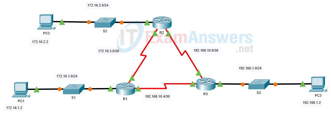
Topology

8.2.1 Packet Tracer – Configure OSPFv2 in a Single Area
Addressing Table
| Device | Interface | IP Address | Subnet Mask |
|---|---|---|---|
| R1 | G0/0 | 172.16.1.1 | 255.255.255.0 |
| S0/0/0 | 172.16.3.1 | 255.255.255.252 | |
| S0/0/1 | 192.168.10.5 | 255.255.255.252 | |
| R2 | G0/0 | 172.16.2.1 | 255.255.255.0 |
| S0/0/0 | 172.16.3.2 | 255.255.255.252 | |
| S0/0/1 | 192.168.10.9 | 255.255.255.252 | |
| R3 | G0/0 | 192.168.1.1 | 255.255.255.0 |
| S0/0/0 | 192.168.10.6 | 255.255.255.252 | |
| S0/0/1 | 192.168.10.10 | 255.255.255.252 | |
| PC1 | NIC | 172.16.1.2 | 255.255.255.0 |
| PC2 | NIC | 172.16.2.2 | 255.255.255.0 |
| PC3 | NIC | 192.168.1.2 | 255.255.255.0 |
Objectives
- Part 1: Configure OSPFv2 Routing
- Part 2: Verify the Configurations
Background
In this activity, the IP addressing is already configured. You are responsible for configuring the three router topology with basic single area OSPFv2 and then verifying connectivity between end devices.
Note: The topology is the same one used in the chapter examples. In addition, the student practiced the configuration of this topology in the Syntax Checker activities. Therefore, the student should be able to complete this activity with minimal assistance.
Instructions
Part 1: Configure OSPFv2 Routing
Step 1: Configure OSPF on the R1, R2 and R3.
Use the following requirements to configure OSPF routing on all three routers:
- Process ID 10
- Router ID for each router: R1 = 1.1.1.1; R2 = 2.2.2.2; R3 = 3.3.3.3
- Network address for each interface
- LAN interface set to passive (do not use the default keyword)
Step 2: Verify OSPF routing is operational.
On each router, the routing table should now have a route to every network in the topology.
Step 3: Verify the Configurations
Each PC should be able to ping the other two PCs. If not, check your configurations.
Answer Scripts
Router R1
enable
conf t
router ospf 10
 router-id 1.1.1.1
 network 172.16.1.0 0.0.0.255 area 0
 network 172.16.3.0 0.0.0.3 area 0
 network 192.168.10.4 0.0.0.3 area 0
 passive-interface GigabitEthernet0/0
end
Router R2
enable
conf t
router ospf 10
 router-id 2.2.2.2
 network 172.16.2.0 0.0.0.255 area 0
 network 172.16.3.0 0.0.0.3 area 0
 network 192.168.10.8 0.0.0.3 area 0
 passive-interface GigabitEthernet0/0
end
Router R3
enable
conf t
router ospf 10
 router-id 3.3.3.3
 network 192.168.1.0 0.0.0.255 area 0
 network 192.168.10.4 0.0.0.3 area 0
 network 192.168.10.8 0.0.0.3 area 0
 passive-interface GigabitEthernet0/0
end

Good Job, 100% correct