Contents
Campus Network Structure
- Hierarchical Network Design 1
- Access, Distribution and Core Layer (Backbone)
- Layer 3 in the Access Layer
- The Cisco Enterprise Campus Architecture
- The Need for a Core Layer
Types of Cisco Switches
- Comparing Layer 2 and Multilayer Switches
- MAC Address Forwarding
- Layer 2 Switch Operation
- Layer 3 (Multilayer) Switch Operation
- Useful Commands for Viewing and Editing Catalyst Switch MAC
- Address Tables
- Frame Rewrite
- Distributed Hardware Forwarding
- Cisco Switching Methods
- Route Caching
- Topology-Based Switching
- Hardware Forward Details
Switching
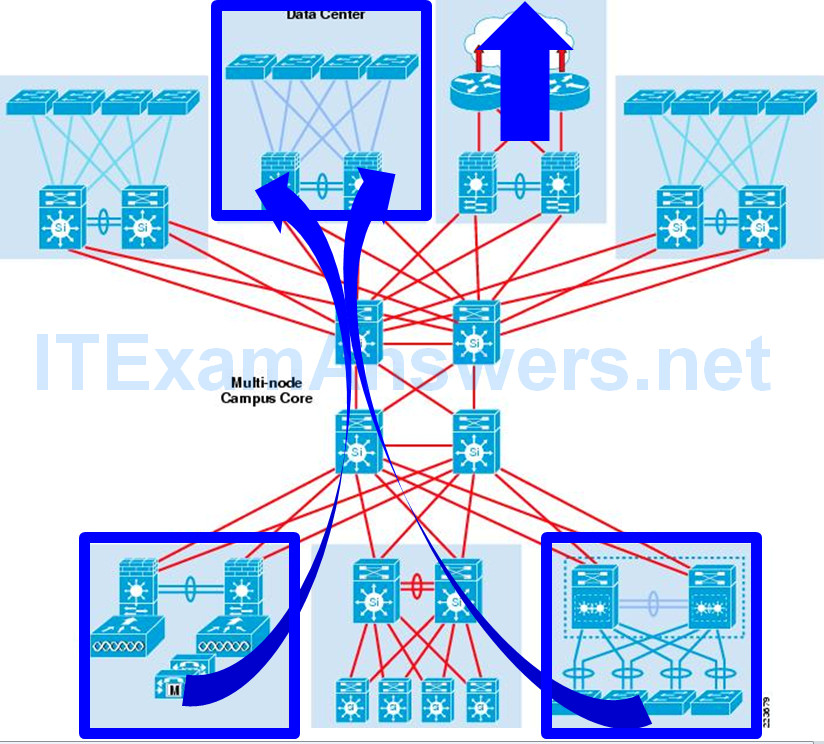
A campus network describes the portion of an enterprise infrastructure that interconnects end devices to services such as intranet resources (residing in the data center) or the Internet.
- End devices: computers, laptops, and wireless access points
- Intranet resources: web pages, call center applications, file and print services, etc.
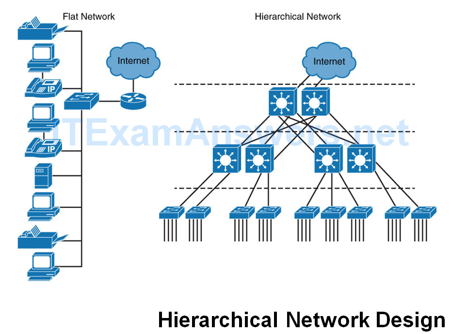
Flat Networks
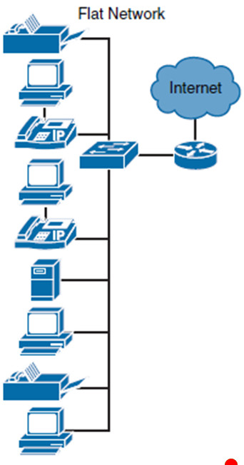
Network were first implemented in a “flat” manner where all PCs, servers, and printers are connected to each other using Layer 2 switches.
- No subnets for any design purposes.
- All devices in the same broadcast domain.
Broadcast packets received by an end device wastes available bandwidth and resources.
- This is not significant with a few devices.
- However, this is a significant waste of resources and bandwidth in large networks.
As a result of broadcast issues and many other limitations, flat networks do not scale to meet the needs of modern enterprise networks or of many small and medium-size businesses.
Hierarchical Design
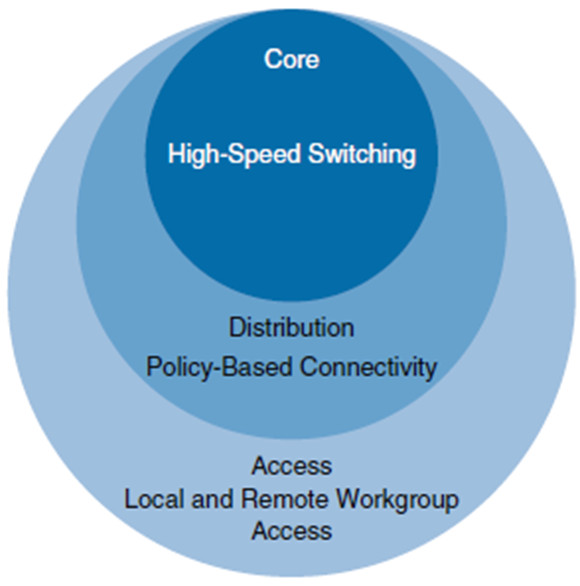
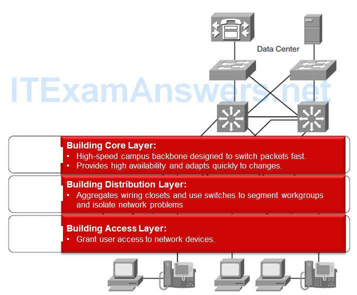
Access layer: Grant the user access to network applications and functions.
Distribution layer: Aggregates the access layer switches wiring closets, floors, or other physical domain by leveraging module or Layer 3 switches.
Core layer (backbone): High-speed backbone, which is designed to switch packets as fast as possible.
- Routing capabilities (also at distribution)
- High level of availability and adapt to changes quickly
- It also provides for dynamic scalability
Hierarchical Model
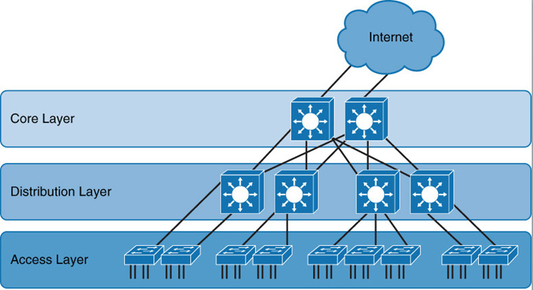
Scalable networks are implemented in a hierarchical manner.
A hierarchical model has the following advantages:
- Provides modularity
- Increases flexibility
- Eases growth and scalability
- Provides for network predictability
- Reduces troubleshooting complexity
Cisco Campus Designs
The Cisco Campus Architecture fundamentally divides networks or their modular blocks into the following hierarchical layers:
This model provides a modular framework that enables flexibility in network design and facilitates implementation and troubleshooting.
Each layer can be focused on specific functions.
Access Layer
The access layer is dedicated to meeting the functions of end-device connectivity.
- Connects a wide variety of devices including Layer 2 switches (e.g. Catalyst 2960) connecting workstations, servers, printers, APs, cameras, ….
The access layer is a feature-rich section of the campus network because it is a best practice to apply features (VoIP, PoE, etc.) as close to the edge as possible.
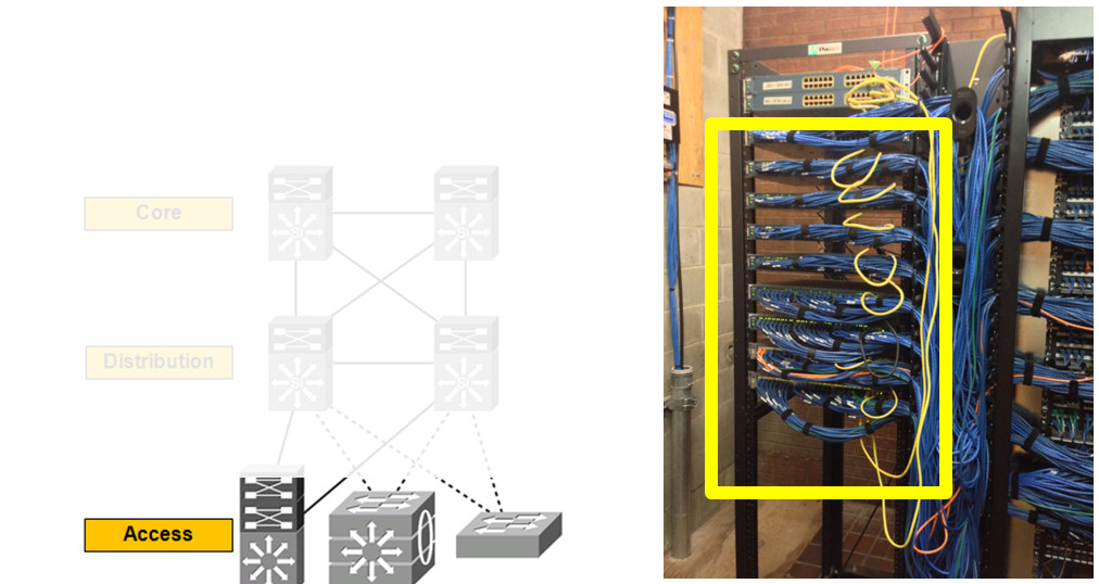
Access Layer Capabilities – What we want (Not necessarily implemented at the access layer)
Distribution Layer
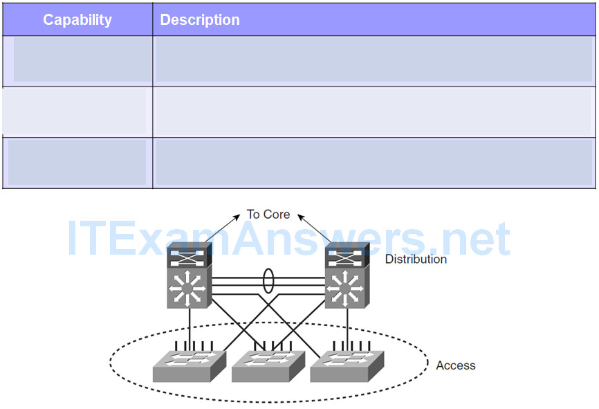
The distribution layer acts as a service and control boundary between the access and core layers.
It consolidates the wiring closets using switches to segment workgroups and isolate network problems in a campus environment.
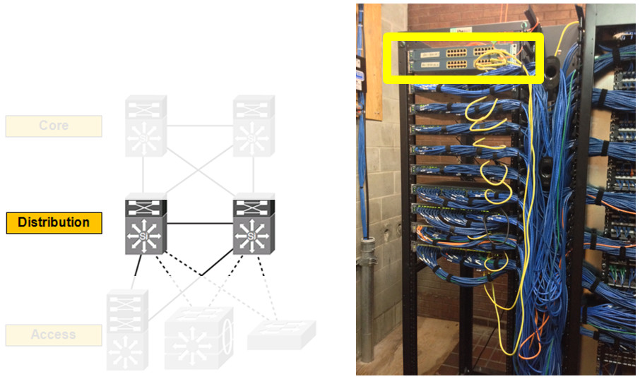
Distribution Layer

Acts as a services and control boundary between the access layer and the core.
Access layer and the core are dedicated special-purpose layers.
- Access layer – Meets the functions of end-device connectivity
- Core layer – Provides nonstop connectivity across the entire campus network.
Distribution layer – Serves multiple purposes.
Distribution Layer Summary
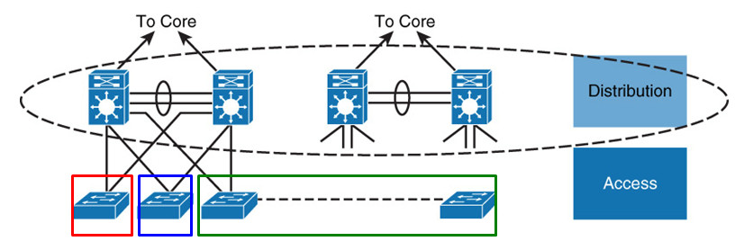
When Layer 3 routing is not configured in the access layer, distribution layer:
- Provides high availability and equal-cost load sharing by interconnecting the core and access layer via at least dual paths
- Generally terminates a Layer 2 domain of a VLAN
- Best not to span same VLAN across multiple access layer switches (unless stackable) to prevent unwanted unicast flooding
- Routes traffic from terminated VLANs to other VLANs and to the core
- Summarizes access layer routes
- Implements policy-based connectivity such as traffic filtering, QoS, and security
- Provides for an FHRP
Core Layer
Backbone for campus connectivity
High level of redundancy and adapt to changes quickly
- Event of the failure of any component (switch, supervisor, line card, or fiber interconnect, power, and so on)
- Permit the occasional, but necessary, hardware and software upgrade or change
Minimal control plane configuration
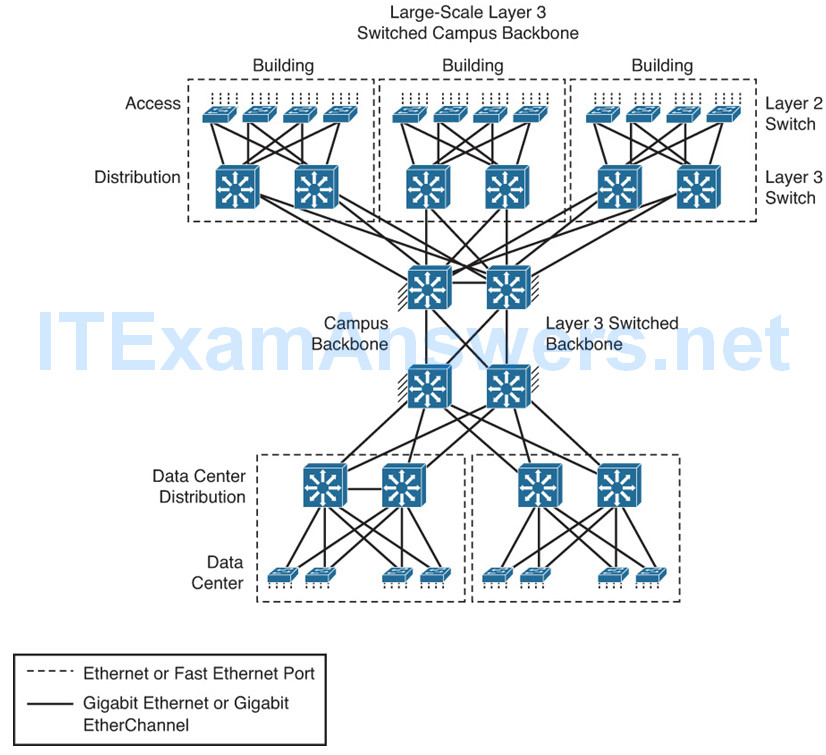
Backbone (core) that binds together all the elements of the campus architecture to include the WAN, the data center, etc.
Core layer interconnects with a data center and edge distribution module to interconnect WAN, remote access, and the Internet.
- The network module operates out of band from the network but is still a critical component.
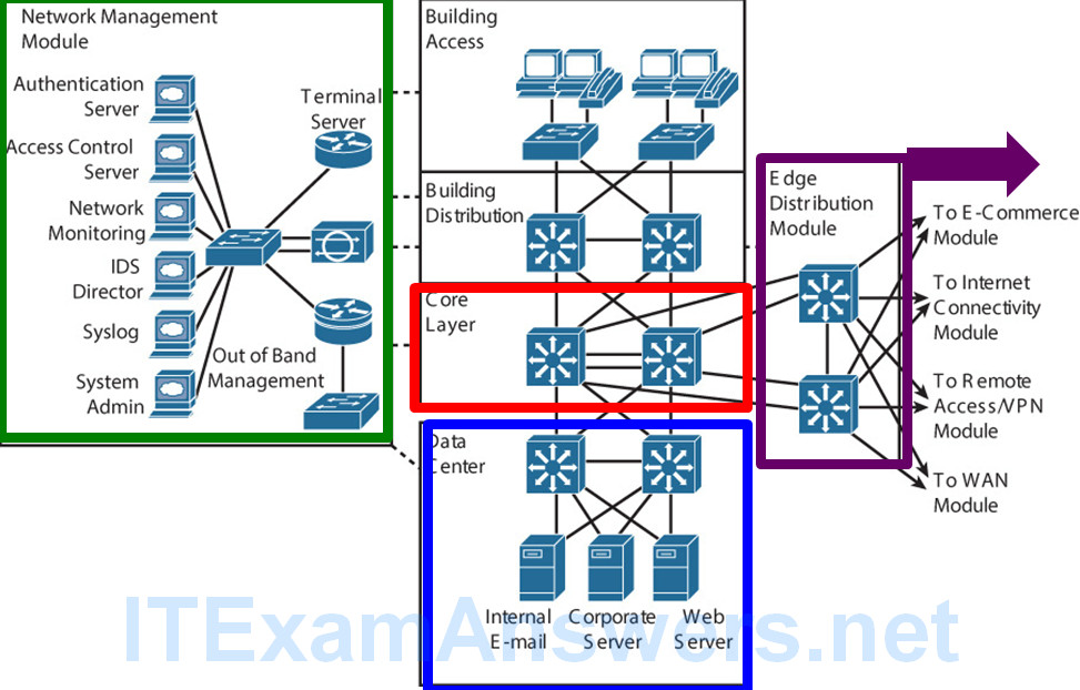
Core Layer Summary
Provides interconnectivity to the data center, the WAN, and other remote networks
High availability, resiliency, and the ability to make software and hardware upgrades without interruption
Designed without direct connectivity to servers, PCs, access points, and so on
Requires core routing capability
Architected for future growth and scalability
Leverages Cisco platforms that support hardware redundancy

Layer 2 or 3 in the Access Layer?
Layer 3 switching or traditional Layer 2 switching ….
…. benefits and drawbacks.
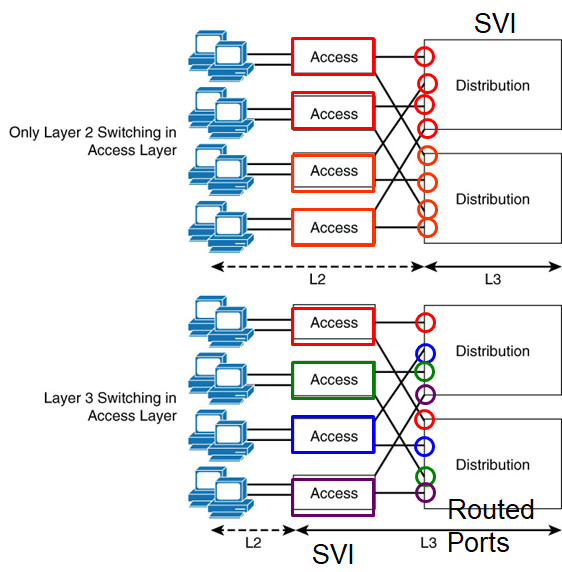
Layer 2 switching design in the access layer may result in suboptimal usage of links between the access and distribution layer.
- Does not scale
- Distribution switch – SVI
Layer 3 switching to the access layer VLANs scales better because VLANs get terminated on the access layer devices.
- Links links between the distribution and access layer switches are routed links (distribution switch has a routed port)
- All access and distribution devices would participate in the routing scheme.
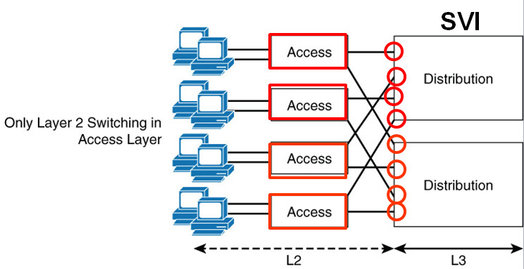
Layer 2-only access design is a traditional, slightly cheaper solution,
- Suffers from suboptimal use of links between access and distribution due to spanning tree.
Layer 3 designs also require careful planning with respect to IP addressing.
- A VLAN on one Layer 3 access device cannot be on another access layer switch in a different part of your network because each VLAN is globally significant.
Asymmetric Routing
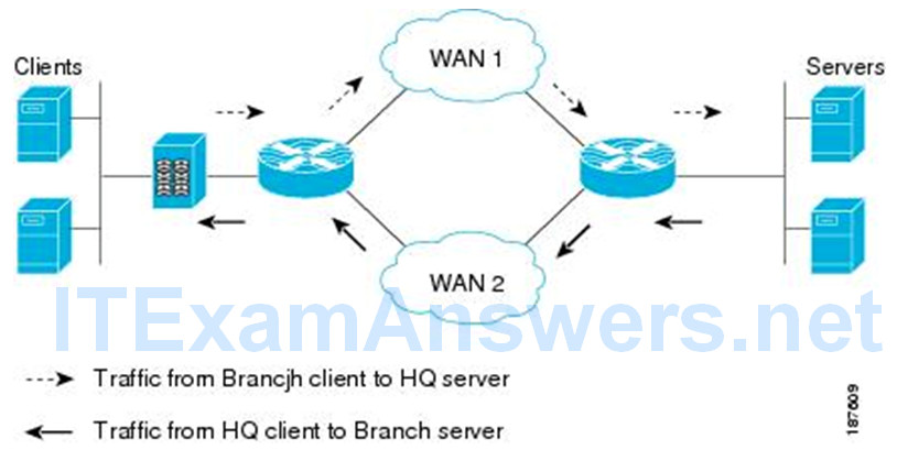
Asymmetric routing – A packet traverses from a source to a destination in one path and takes a different path when it returns to the source.
This is commonly seen in Layer-3 routed networks.
Not necessarily a bad thing – Internet and BGP.
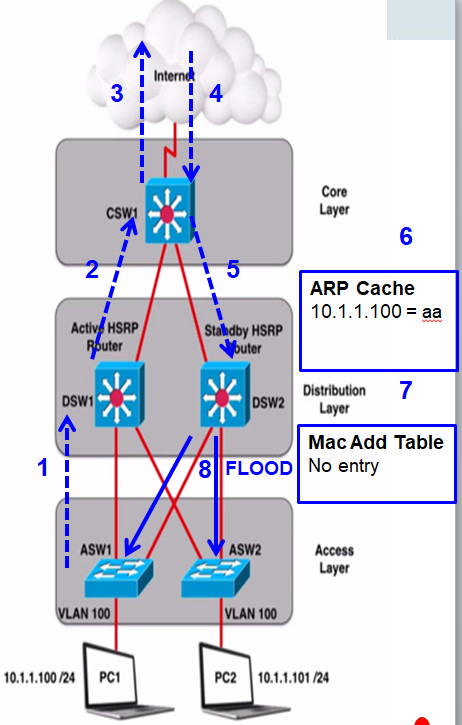
1 – 3: DSW1 (Active HSRP routers) is default gateway for PC1
4 – 5: CSW1 load balances sending return traffic to DSW2 (not a bad thing)
6: DSW2 ARP table (4 hour default) has entry for PC1 10.1.1.100…
7: But there is no entry in its MAC table (times out 5 min)
Both access layer switches are on same VLAN (not a best practice).
8: So, DSW2 floods “frames” out all ports on that VLAN (unicast flooding)
Because DSW2 never sees traffic sourced from PC1 (10.1.1.100) it never updates is MAC address table and unicast flooding always occurs.
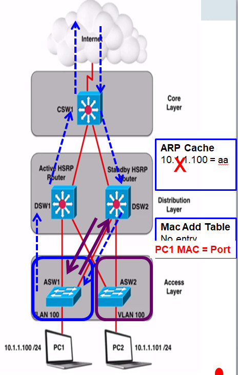
Solutions:
1. Change ARP timer (4 hours IOS) to be less than MAC Address Table (5 minutes) timer
DSW2 would need send ARP request for 10.1.1.100
PC1 would send ARP Reply
ARP Reply in Ethernet frame, so DSW2 can now add PC1’s MAC address to its MAC address table
DSW2 will now send packet for 10.1.1.100 only out the one port
2. Do not span VLAN across multiple access layer switches
Enterprise Network
Cisco enterprise campus architecture refers to the traditional hierarchical campus network applied to the network design
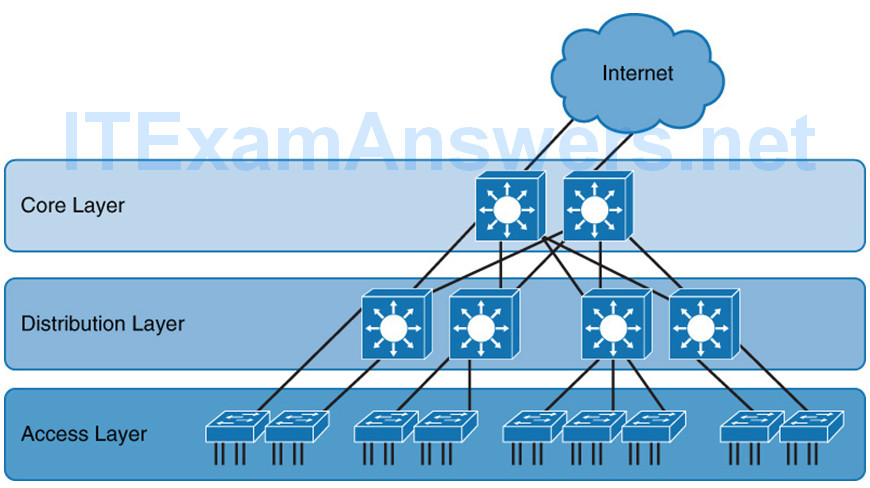
- Divides the enterprise network into physical, logical, and functional areas while leveraging the hierarchical design.
- No absolute rules apply to how a campus network is physically built.
- Does not need to be the common three physical tiers of switches
- Smaller campus might have two tiers of switches in which the core and distribution elements are combined in one physical switch: a collapsed distribution and core.
- Network may have four or more physical tiers of switches because the scale, wiring plant, or physical geography of the network might require that the core be extended.

Collapsed Core
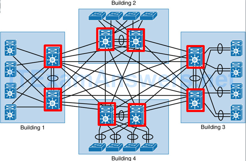
- Smaller campus might have two tiers of switches in which the core and distribution elements are combined in one physical switch: a collapsed distribution and core.
- Doesn’t scale and routing complexity also increases
Types of Cisco Switches
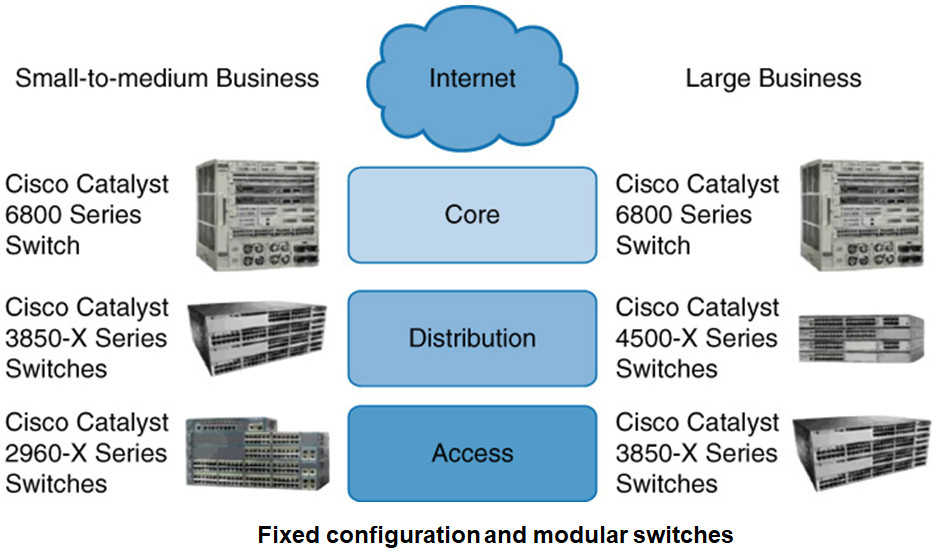
Layer 2 and Layer 3 Switches
- Layer 2 Ethernet switch operates at the Data Link Layer.
- Forwarding frames based on the destination MAC address.
- No contention on the media, all hosts can operate in full-duplex mode
- Half duplex is legacy and applies only to hubs and older 10/100-Mbps switches,
1 Gbps operates by default at full duplex. - Store-n-forward mode – the frame is checked for errors, and frames with a valid cyclic redundancy check (CRC) are regenerated and transmitted.
- Cut-through switching – Switch frames based only on reading the Layer 2 information and bypassing the CRC check
lowers the latency of the frame transmission.
End device NIC or an upper-level protocol will eventually discard the bad frame. - Most Catalyst switches are store-n-forward.
MAC Address Forwarding
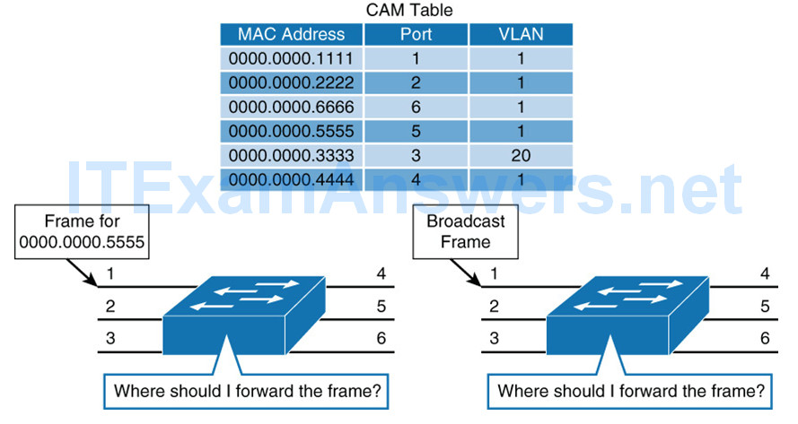
- See Chapter 1 PowerPoint.
- Unknown unicast flooding
Layer 2 Switch Operation
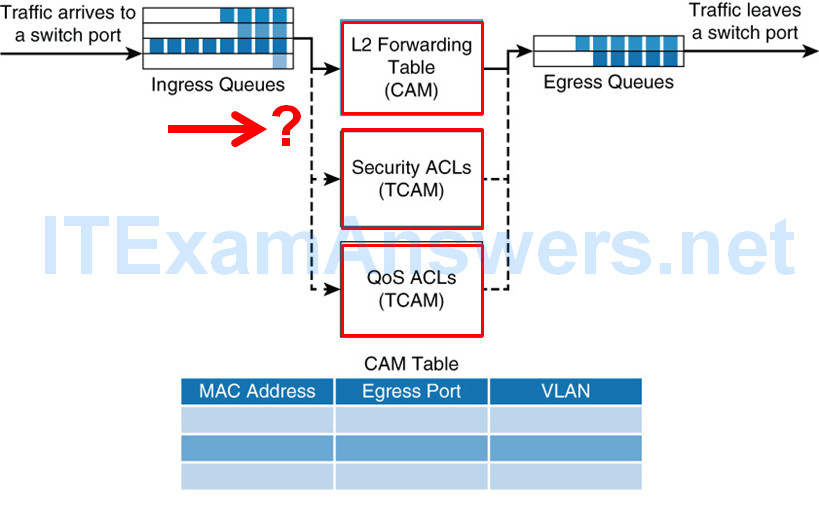
- Switch receives a frame, places the frame into an ingress queue.
- Where should the frame be forwarded?
- Are there restrictions preventing the forwarding of the frame?
- Is there any prioritization or marking that needs to be applied to the frame?
- Layer 2 forwarding table: MAC table, contains information about where to forward the frame
Destination MAC address – forward the frames to the destination ports specified in the table.
Not found, the frame is flooded through all ports in the same VLAN. - ACLs:
Layer 3 switches support ACLs based on both MAC and IP addresses
Layer 2 switches support ACLs only with MAC addresses. - QoS: Incoming frames can be classified according to QoS parameters.
Traffic can then be marked, prioritized, or rate-limited.
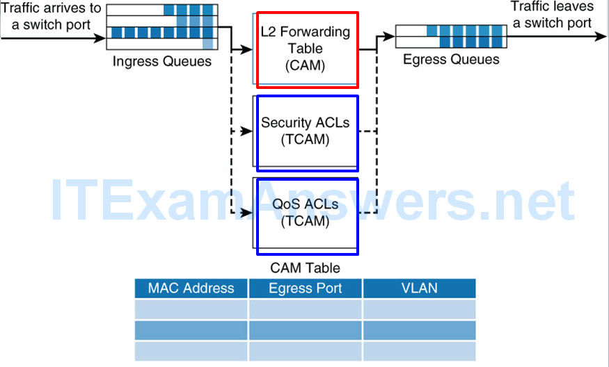
- Specialized hardware…
- MAC table, switches use content-addressable memory (CAM)
- ACL and QoS tables are housed in ternary content-addressable memory (TCAM).
- Both CAM and TCAM are extremely fast access and allow for line-rate switching performance.
CAM supports only two results: 0 or 1.
CAM is useful for Layer 2 forwarding tables. - TCAM provides three results: 0, 1, and don’t care.
Most useful for building tables for searching on longest matches, such as IP routing tables organized by IP prefixes. - Applying ACLs does not affect the performance of the switch.
Layer 3 Switch Operation
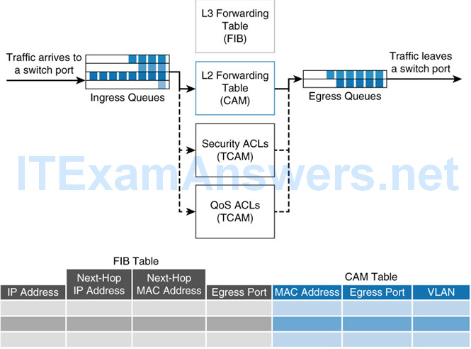
Multilayer switches perform Layer 2 switching and ….
……also forward frames based on Layer 3 and 4 information.
- Not only combine the functions of a switch and a router but also….
- … add a flow cache component.
- Apply the same behavior as Layer 2 switches but add an additional parallel lookup for how to route a packet
Frame Rewrite
When packets transit through a router or L3 switch, the following verifications must occur:
- The incoming frame checksum is calculated and verified to ensure that no frame corruption or alteration occurs during transit.
- The incoming IP header checksum is calculated and verified to ensure that no packet corruption or alteration occurs during transit.
The routing decision is made.
IP packets are then rewritten on the output interface:
- The source MAC changes to the outgoing router MAC address.
- The destination MAC address changes to the next-hop router’s MAC.
- The TTL is decremented by 1 (IP header checksum is recalculated).
- The frame checksum is recalculated.
Distributed Hardware Forwarding

Network devices contain at least three planes of operation:
- Management plane – Responsible for the network management, such as SSH access and SNMP
- May operate over an out-of-band (OOB) port
- Control plane – Responsible for protocols and routing decisions,
- Forwarding plane – Responsible for the actual routing (or switching) of most packets
Multilayer switches must achieve high performance at line rate across a large number of ports.
To do so, multilayer switches deploy independent control and forwarding planes.
Control plane will program the forwarding plane on how to route packets.
Process Switching
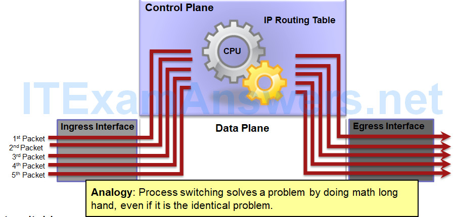
Earliest switching method.
This is an older packet forwarding mechanism.
- When a packet arrives on an interface, it is forwarded to the control plane where the CPU examines the routing table, determines the exit interface and forwards the packet.
- It does this for every packet, even if the destination is the same for a stream of packets.
Fast Switching
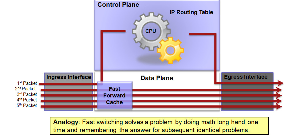
As routers had to process more packets, it was determined process switching was not fast enough.
Next evolution in packet switching was Fast Switching.
- The first packet is process-switched (CPU + routing table) but it also uses a fast-switching cache to store next-hop information of the flow.
- The next packets in the flow are forwarded using the cache and without CPU intervention.
CEF Switching
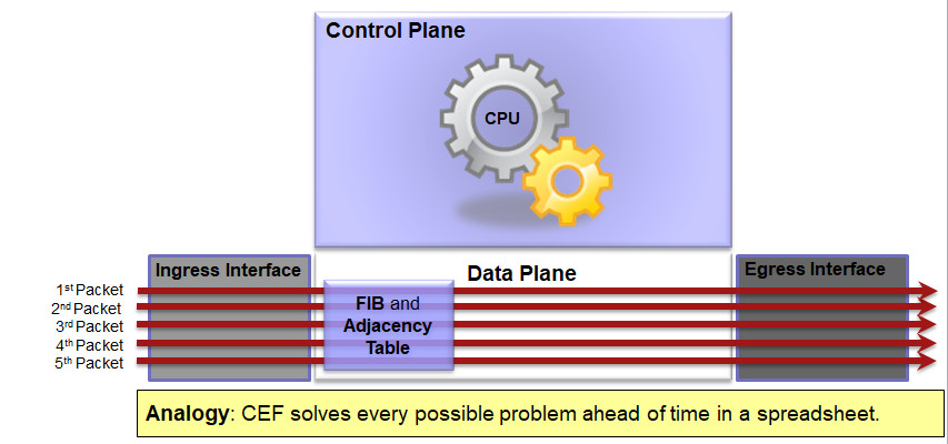
Preferred and default Cisco IOS packet-forwarding mechanism
- CEF copies the routing table to the Forwarding Information Base (FIB)
- CEF creates an adjacency table which contains all the layer 2 information a router would have to consider when forwarding a packet such as Ethernet destination MAC address.
- The adjacency table is created from the ARP table.
Route Caching
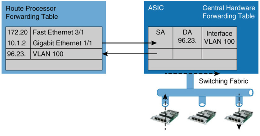
- Route caching is the fast switching equivalent in Cisco Catalyst switches.
Route once, switch many - First packet in a stream is switched in software by the route processor
Forwarding decision programmed into a cache table (the hardware forwarding table) - Subsequent packets in the flow are switched in the hardware, commonly referred to as using application-specific interface circuits (ASICs).
- Entries will time out after they have been unused for a period of time.
- Route caching will always forward at least one packet in a flow using software.
- Route caching carries many other names, such as:
- NetfFow LAN switching
- Flow-based or demand-based switching
- Route once, switch many
First packet in a stream is switched in software by the route processor.
Information is stored in a hardware forwarding table as a flow.
All subsequent packets are switched in hardware.
Topology-based Switching
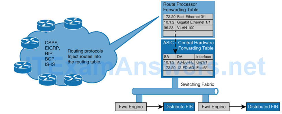
- Topology-based switching is the CEF equivalent
- Offers the better performance and scalability than route caching
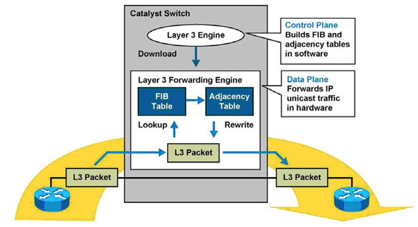
- lCEF uses information in the routing table to populate a route cache (known as an FIB)
- lThe FIB even handles the first packet of a flow
CEF Load Balancing

CEF supports both load balancing based on:
- Source IP address and destination IP address combination
- Source and destination IP plus TCP/UDP port number
Packets with same source-destination host pair are guaranteed to take the same path, even if multiple paths are available.
This ensures that packets for a given host pair arrive in order, which in some cases may be the desired behavior with legacy applications.
Load balancing based only on source and destination IP address has a few shortcomings.
- This load-balancing method always selects the same path for a given host pair, a heavily used source-destination pair, such as a firewall to web server, might not leverage all available links.
- “Polarizes” the traffic by using only one path for a given host pair, thus effectively negating the load-balancing benefit of the multiple paths for that particular host pair.
