CCNA Routing and Switchingz Scaling Networks
Form A ScaN EIGRP Practice Skills Assessment - PT
Practice Skills Assessment - EIGRP
A few things to keep in mind while completing this activity:
1. Do not use the browser Back button or close or reload any exam windows during the exam.
2. Do not close Packet Tracer when you are done. It will close automatically.
3. Click the Submit Assessment button in the browser window to submit your work.
Introduction
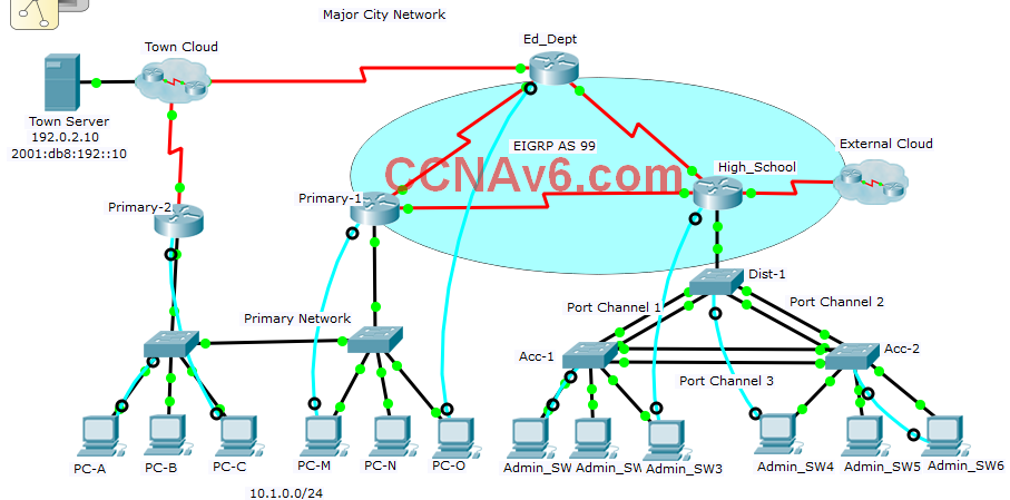
In this practice skills assessment, you will configure the Major City network with EIGRP routing and enhanced switching. The network is configured with both IPv4 and IPv6 on all devices. This will allow you to implement routing in both EIGRP for IPv4 and EIGRP for IPv6. Your goal is to achieve full connectivity between all LAN hosts and the remote Town Server in both IPv4 and IPv6. For a full list of tasks, see below.
You are not required to configure the following:
• The Primary network switches
• Most of the network hosts and the Town Server
• The Town Cloud
All IOS device configurations should be completed from a direct terminal connection to the device console.
You will practice and be assessed on the following skills:
• Configuration of IPv4 and IPv6 default routes
• Configuration of EIGRP for IPv4
• Configuration of EIGRP for IPv6
• Customization of EIGRP for IPv4 and EIGRP for IPv6
You will configure specific devices with the following:
Router Ed_Dept:
• IPv4 and IPv6 default route
• EIGRP for IPv4 and EIGRP for IPv6
• Router ID
• Interface bandwidth
• Redistribution of default routes
Router Primary-1:
• EIGRP for IPv4 and EIGRP for IPv6
• HSRP
• Interface bandwidth
• EIGRP for IPv4 passive interface
Router Primary-2:
• IPv4 default route
• HSRP
Router High_School:
• EIGRP for IPv4 and EIGRP for IPv6
• Router ID
• Interface bandwidth
• EIGRP for IPv4 passive interfaces
Switch Dist-1:
• RPVST+ activation
• RPVST primary root bridge priority
• EtherChannel channel groups
• Static trunking with native VLAN
• DTP
• VTP
Switch Acc-1:
• RPVST+ activation
• PortFast
• BPDU Guard
• EtherChannel channel groups
• Static trunking with native VLAN
• DTP
• VTP
Switch Acc-2:
• RPVST+ activation
• RPVST secondary root bridge priority
• EtherChannel channel groups
• Static trunking with native VLAN
• DTP
• VTP
PC PC-A:
• Default gateway
PC PC-M:
• Default gateway
Addressing Table
Use the following addresses to configure the network. Some addresses are preconfigured on devices that you are not required to configure, and are provided for reference purposes only.
| Device | Interface | Address Information |
| Ed_Dept (DataCenter) |
S0/0/0 | 192.168.100.9/30 |
| 2001:DB8:1A::1/64 FE80::1 link local |
||
| S0/0/1 | 192.168.100.21/30 | |
| 2001:DB8:1B::1/64 FE80::1 link local |
||
| S0/1/0 | 203.0.113.18/30 | |
| 2001:DB8:99::2/64 FE80::1 link local |
||
| Primary-1 (Hospital_1) (CCNAv6.com) |
S0/0/0 | 192.168.100.10/30 |
| 2001:DB8:1A::2/64 FE80::2 link local |
||
| S0/0/1 | 192.168.100.33/30 | |
| 2001:DB8:2::1/64 FE80::2 link local |
||
| G0/0 | 10.1.0.3/24 | |
| 2001:DB8:20::3/64 FE80::2 link local |
||
| Primary-2 (Clinic_10) |
S0/0/0 | 203.0.113.22/30 |
| 2001:DB8:100::2/64 FE80::22 link local |
||
| G0/0 | 10.1.0.2/24 | |
| 2001:DB8:20::2/64 FE80::22 link local |
||
| High_School (Hospital_2) |
S0/0/0 | 192.168.100.34/30 |
| 2001:DB8:2::2/64 FE80::3 link local |
||
| S0/0/1 | 192.168.100.22/30 | |
| 2001:DB8:1B::2/64 FE80::3 link local |
||
| S0/1/0 | 2001:DB8:E::2/64 | |
| G0/0.10 | 10.10.0.1/24 | |
| 2001:DB8:3:10::1/64 FE80::3 link local |
||
| G0/0.15 | 10.15.0.1/24 | |
| 2001:DB8:3:15::1/64 FE80::3 link local |
||
| G0/0.20 | 10.20.0.1/24 | |
| 2001:DB8:3:20::1/64 FE80::3 link local |
||
| External (Remote) |
N/A | 2001:DB8:E::1/64 |
Instructions
Part I: EIGRP and HSRP Configuration
Step 1-1: Configure default static routes.
1. Configure IPv4 and IPv6 default static routes on the Ed_Dept router to the Town Cloud. Use the outgoing interface value in your configuration.
2. Configure the Primary-2 router with an IPv4 default route to the Town Cloud using the outgoing interface value.
Step 1-2: Configure EIGRP for IPv4
On the Ed_Dept, Primary-1, and High_School routers only, configure EIGRP for IPv4.
1. Use an AS number of 99 for all EIGRP routers.
2. Activate routing for the appropriate networks. Use inverse masks that specify only addresses within the networks.
3. Set the router IDs as follows:
- Ed_Dept: 1.1.1.1
- Primary-1: 2.2.2.2
- High_School: 3.3.3.3
Step 1-3: Configure EIGRP for IPv6.
Configure EIGRP for IPv6 on the Ed_Dept, Primary-1, and High_School routers.
1. Use an AS number of 99 for all EIGRP routers.
2. Activate routing for the appropriate networks. Note that router Primary-2 does not use EIGRP routing.
3. Set the router IDs as follows:
- Ed_Dept: 1.1.1.1
- Primary-1: 2.2.2.2
- High_School: 3.3.3.3
Important: Your EIGRP for IPv6 configuration can only be checked for this assessment indirectly. After you have completed your configuration, in order to get credit for EIGRP for IPv6 routing, you must do the following:
1. On host PC-B, go to the Desktop tab and open the Command Prompt.
2. Enter telnet 2001:DB8:E::1
3. If your EIGRP for IPv6 configuration is correct, you should be able to reach the External router with the address above. Authenticate your Telnet session with the password cisco.
4. Move to privileged EXEC mode using the password admin.
5. Activate the G0/0 interface of the router.
6. Exit the Telnet session.
In your score report, for EIGRP for IPv6 interface activation, you will see an item for activation of the router External G0/0 interface. If you got this item correct, you have correctly activated EIGRPv6 on the required routers.
Step 1-4: Customize EIGRP for IPv4 operation.
Customize EIGRP for IPv4 as follows:
1. Set the interface bandwidth for the two EIGRP interfaces on router Ed_Dept to match the interface clock speed.
2. Set the interface bandwidth for the serial interfaces on routers Primary-1 and High_School to match the bandwidth of the interfaces on router Ed_Dept.
3. Configure all LAN interfaces, both physical and virtual, so that EIGRP messages are not sent into the LANs.
4. Configure Ed_Dept so that the static default route is automatically shared with the other EIGRP routers.
Step 1-5: Customize EIGRP for IPv6 operation.
Configure the Ed_Dept router to automatically share the IPv6 static route with the other EIGRP for IPv6 routers.
Step 1-6: Configure HSRP as follows:
Configure the Primary-1 and Primary-2 routers with HSRP. In this scenario, the hosts on the Primary network are to be dual-homed. In other words, if the active Primary-1 router fails, the Primary network hosts will use the Primary-2 router as their gateway. Although connectivity to the rest of the Major City network will not be available, the hosts will be able to access the Internet through the Primary-2 router, because HSRP will switch to using it as the default gateway for the hosts. You will configure Primary-1 as the active router, and Primary-2 as the backup using HSRP.
Requirements:
1. Configure router Primary-1 with HSRP as follows:
- The group number is 1.
- Virtual gateway IP address: 10.1.0.1
- The router should immediately become the active router.
- The priority should be 150.
2. Configure router Primary-2 as follows:
- Virtual gateway IP address: 10.1.0.1
- Leave all other HSRP values at the default.
3. In order for the Primary-2 router to provide connectivity to the Internet, it requires a default route to be configured as you are directed in Step 1-1 above. This router is not configured with EIGRP.
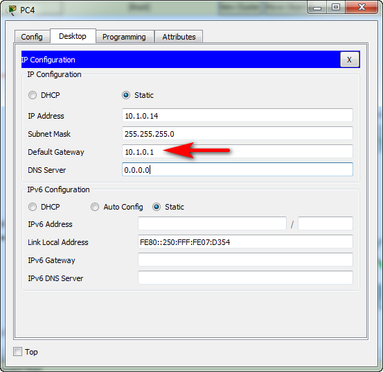
4. Configure hosts PC-A and PC-M with the correct default gateway addresses.
Part II: Enhanced Switching Technologies
Step 2-1: Configure link aggregation with EtherChannel.
Configure the three EtherChannel links between switches Dist-1, Acc-1, and Acc-2:
| Port Channel | Device | Interfaces |
| 1 | Dist-1 | Fa0/3 Fa0/4 |
| Acc-1 | Fa0/3 Fa0/4 |
|
| 2 | Dist-1 | Fa0/5 Fa0/6 |
| Acc-2 | Fa0/5 Fa0/6 |
|
| 3 | Acc-1 | Fa0/1 Fa0/2 |
| Acc-2 | Fa0/1 Fa0/2 |
1. Configure EtherChannels with the LACP protocol using the information in the table.
2. Both sides of the channel should ask if the other side is willing to participate in the channel.
Step 2-2: Configure Trunking.
Configure trunking as follows:
1. The trunk between High_School and Dist-1 should be active.
2. The trunk between High_School and Dist-1 should use the native VLAN value preconfigured on High_School.
3. Configure all of the port channel interfaces as static trunks with the appropriate native VLAN.
4. Disable DTP negotiation on all of the trunks.
Step 2-3: Configure VTP.
Configure switches Dist-1, Acc-1, and Acc-2 with VTP as follows:
1. Switch Dist-1 should be the only VTP server in the domain.
2. The other switches in the domain should be configured as clients.
Use the following values:
- VTP domain: TownEd
- VTP Password: TWE_123!
Note: In order for the VLANs to be distributed from the VTP server to the client switches, you may need to take action to increment the VTP revision number. This can be done by adding and deleting a VLAN on the VTP server after the switches in the domain have complete VTP configurations and trunking is operating correctly.
Step 2-4: Configure RPVST.
Configure switches Dist-1, Acc-1, and Acc-2 with RPVST+ as follows:
1. All of the switches should use Rapid Spanning Tree Protocol.
2. Switch Dist-1 should be configured as the root bridge for VLANs 10, 15, and 20 with a priority value of 24576.
3. Switch Acc-2 should be configured as the secondary root bridge for VLANs 10, 15, and 20 with a priority value of 28672.
4. Switch Acc-1 should be left with its default priority.
Step 2-5: Configure PortFast and BPDU Guard.
Configure only switch Acc-1 as follows:
1. Configure all of the access ports that are assigned to VLANs with BPDU Guard.
2. Configure the same ports with PortFast.
If EIGRP is configured properly, full adjacencies should be formed between all routers in the EIGRP AS. The hosts on the LANs should be able to communicate with the hosts on all other LANs and the Town Server using both IPv4 and IPv6.
Connect the PC to the Switch/Router using a Console cable
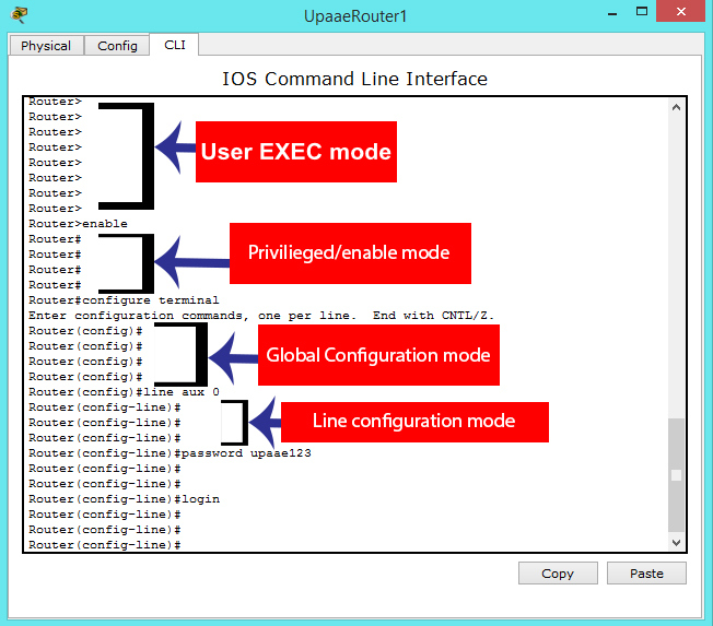
Ed_Dept Router:
en
conf ter
ip route 0.0.0.0 0.0.0.0 s0/1/0
ipv6 unicast-routing
ipv6 route ::/0 s0/1/0
router eigrp 99
network 192.168.100.8 0.0.0.3
network 192.168.100.20 0.0.0.3
eigrp router-id 1.1.1.1
exit
ipv6 router eigrp 99
eigrp router-id 1.1.1.1
no shutdown
exit

int s0/0/0
ipv6 eigrp 99

int s0/0/1
ipv6 eigrp 99
exit

int s0/1/0
ipv6 eigrp 99
exit

int s0/0/0
bandwidth 2000
exit

int s0/0/1
bandwidth 2000
exit

router eigrp 99
redistribute static
exit
ipv6 router eigrp 99
redistribute static
Primary-2 Router:
en
conf ter
ip route 0.0.0.0 0.0.0.0 s0/0/0
int g0/0
standby 1 ip 10.1.0.1
standby version 2
Primary-1 Router
en
conf ter
router eigrp 99
network 10.1.0.0 0.0.0.255
network 192.168.100.8 0.0.0.3
network 192.168.100.32 0.0.0.3
eigrp router-id 2.2.2.2
exit
ipv6 unicast-routing
ipv6 router eigrp 99
eigrp router-id 2.2.2.2
no shutdown
exit
int s0/0/1
ipv6 eigrp 99
int s0/0/0
ipv6 eigrp 99
int g0/0
ipv6 eigrp 99
exit

int s0/0/0
bandwidth 2000
exit
router eigrp 99
passive-interface g0/0
exit

int g0/0
standby 1 ip 10.1.0.1
standby 1 preempt
standby 1 priority 150
standby version 2
High_School Router
en
conf ter
router eigrp 99
network 10.10.0.0 0.0.0.255
network 10.15.0.0 0.0.0.255
network 10.20.0.0 0.0.0.255
network 192.168.100.20 0.0.0.3
network 192.168.100.32 0.0.0.3
eigrp router-id 3.3.3.3
exit

ipv6 unicast-routing
ipv6 router eigrp 99
eigrp router-id 3.3.3.3
no shutdown
exit
int g0/0.10
ipv6 eigrp 99
int g0/0.15
ipv6 eigrp 99
int g0/0.20
ipv6 eigrp 99
exit

int s0/0/0
ipv6 eigrp 99
int s0/0/1
ipv6 eigrp 99
int s0/1/0
ipv6 eigrp 99
exit
int s0/0/1
bandwidth 2000
exit

router eigrp 99
passive-interface g0/0.10
passive-interface g0/0.15
passive-interface g0/0.20
exit
int g0/0
no sh
Dist-1 Switch
en
conf ter
int range f0/3-4
channel-group 1 mode active
int range f0/5-6
channel-group 2 mode active
exit
int g0/1
no shutdown

int g0/1
switchport mode trunk
switchport trunk native vlan 99
int g0/1
switchport nonegotiate

int range f0/3-4
switchport mode trunk
switchport trunk native vlan 99
int port-channel 1
switchport mode trunk
switchport trunk native vlan 99
switchport nonegotiate

int range f0/5-6
switchport mode trunk
switchport trunk native vlan 99
int port-channel 2
switchport mode trunk
switchport trunk native vlan 99
switchport nonegotiate
exit

vtp mode server
vtp domain TownEd
vtp password TWE_123!
vtp version 2

spanning-tree mode rapid-pvst
spanning-tree vlan 10,15,20 priority 24576
Acc-1 Switch:
en
conf ter
int range f0/3-4
channel-group 1 mode active
int range f0/1-2
channel-group 3 mode active
exit

int range f0/3-4
switchport mode trunk
switchport trunk native vlan 99
int port-channel 1
switchport mode trunk
switchport trunk native vlan 99
switchport nonegotiate
int range f0/1-2
switchport mode trunk
switchport trunk native vlan 99
int port-channel 3
switchport mode trunk
switchport trunk native vlan 99
switchport nonegotiate
exit

vtp mode client
vtp domain TownEd
vtp password TWE_123!
vtp version 2
spanning-tree mode rapid-pvst
int range f0/10-24
spanning-tree bpduguard enable
spanning-tree portfast
Acc-2 Switch
en
conf ter
int range f0/5-6
channel-group 2 mode active

int range f0/1-2
channel-group 3 mode active
exit

int range f0/5-6
switchport mode trunk
switchport trunk native vlan 99

int port-channel 2
switchport mode trunk
switchport trunk native vlan 99
switchport nonegotiate
int range f0/1-2
switchport mode trunk
switchport trunk native vlan 99

int port-channel 3
switchport mode trunk
switchport trunk native vlan 99
switchport nonegotiate
exit

vtp mode client
vtp domain TownEd
vtp password TWE_123!

spanning-tree mode rapid-pvst
spanning-tree vlan 10,15,20 priority 28672
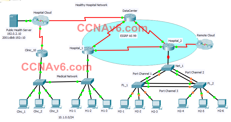
On host "PC-B", go to the "Desktop tab" >> "Command Prompt".
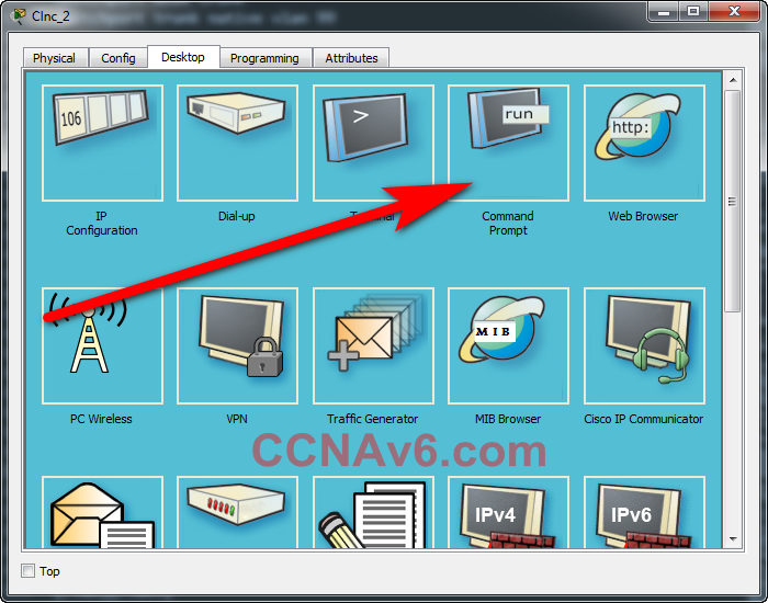
- Enter telnet 2001:DB8:E::1
- Authenticate your Telnet session with the password cisco.
- Move to privileged EXEC mode using the password admin.
C:\>telnet 2001:DB8:E::1
cisco
en
admin
conf ter
int g0/0
no sh
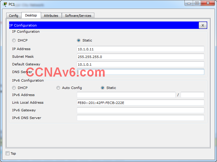
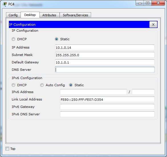
Additional Default Gateway IP: 10.1.0.1 for PCs PC-A & PC-M
Gateway IP address: 10.1.0.1
Scaling Networks - Practice Skills Assessment - EIGRP
Connect the PC to the Switch/Router using a Console cable

DataCenter Router:
en
conf ter
ip route 0.0.0.0 0.0.0.0 s0/1/0
ipv6 unicast-routing
ipv6 route ::/0 s0/1/0
router eigrp 99
network 192.168.100.8 0.0.0.3
network 192.168.100.20 0.0.0.3
eigrp router-id 1.1.1.1
exit
ipv6 router eigrp 99
eigrp router-id 1.1.1.1
no shutdown
exit

int s0/0/0
ipv6 eigrp 99

int s0/0/1
ipv6 eigrp 99
exit

int s0/1/0
ipv6 eigrp 99
exit

int s0/0/0
bandwidth 2000
exit

int s0/0/1
bandwidth 2000
exit

router eigrp 99
redistribute static
exit
ipv6 router eigrp 99
redistribute static
Clinic_10 Router:
en
conf ter
ip route 0.0.0.0 0.0.0.0 s0/0/0
int g0/0
standby 1 ip 10.1.0.1
standby version 2
Hospital_1 Router:
en
conf ter
router eigrp 99
network 10.1.0.0 0.0.0.255
network 192.168.100.8 0.0.0.3
network 192.168.100.32 0.0.0.3
eigrp router-id 2.2.2.2
exit
ipv6 unicast-routing
ipv6 router eigrp 99
eigrp router-id 2.2.2.2
no shutdown
exit
int s0/0/1
ipv6 eigrp 99
int s0/0/0
ipv6 eigrp 99
int g0/0
ipv6 eigrp 99
exit

int s0/0/0
bandwidth 2000
exit
router eigrp 99
passive-interface g0/0
exit

int g0/0
standby 1 ip 10.1.0.1
standby 1 preempt
standby 1 priority 150
standby version 2
Hospital_2 Router:
en
conf ter
router eigrp 99
network 10.10.0.0 0.0.0.255
network 10.15.0.0 0.0.0.255
network 10.20.0.0 0.0.0.255
network 192.168.100.20 0.0.0.3
network 192.168.100.32 0.0.0.3
eigrp router-id 3.3.3.3
exit

ipv6 unicast-routing
ipv6 router eigrp 99
eigrp router-id 3.3.3.3
no shutdown
exit
int g0/0.10
ipv6 eigrp 99
int g0/0.15
ipv6 eigrp 99
int g0/0.20
ipv6 eigrp 99
exit

int s0/0/0
ipv6 eigrp 99
int s0/0/1
ipv6 eigrp 99
int s0/1/0
ipv6 eigrp 99
exit
int s0/0/1
bandwidth 2000
exit

router eigrp 99
passive-interface g0/0.10
passive-interface g0/0.15
passive-interface g0/0.20
exit
int g0/0
no sh
Net_1 Switch:
en
conf ter
int range f0/3-4
channel-group 1 mode active
int range f0/5-6
channel-group 2 mode active
exit
int g0/1
no shutdown

int g0/1
switchport mode trunk
switchport trunk native vlan 99
int g0/1
switchport nonegotiate

int range f0/3-4
switchport mode trunk
switchport trunk native vlan 99
int port-channel 1
switchport mode trunk
switchport trunk native vlan 99
switchport nonegotiate

int range f0/5-6
switchport mode trunk
switchport trunk native vlan 99
int port-channel 2
switchport mode trunk
switchport trunk native vlan 99
switchport nonegotiate
exit

vtp mode server
vtp domain HospSwi
vtp password HPS-789*
vtp version 2

spanning-tree mode rapid-pvst
spanning-tree vlan 10,15,20 priority 24576
FL_1 Switch:
en
conf ter
int range f0/3-4
channel-group 1 mode active
int range f0/1-2
channel-group 3 mode active
exit

int range f0/3-4
switchport mode trunk
switchport trunk native vlan 99
int port-channel 1
switchport mode trunk
switchport trunk native vlan 99
switchport nonegotiate
int range f0/1-2
switchport mode trunk
switchport trunk native vlan 99
int port-channel 3
switchport mode trunk
switchport trunk native vlan 99
switchport nonegotiate
exit

vtp mode client
vtp domain HospSwi
vtp password HPS-789*
vtp version 2
spanning-tree mode rapid-pvst
int range f0/10-24
spanning-tree bpduguard enable
spanning-tree portfast
FL_2 Switch:
en
conf ter
int range f0/5-6
channel-group 2 mode active

int range f0/1-2
channel-group 3 mode active
exit

int range f0/5-6
switchport mode trunk
switchport trunk native vlan 99

int port-channel 2
switchport mode trunk
switchport trunk native vlan 99
switchport nonegotiate
int range f0/1-2
switchport mode trunk
switchport trunk native vlan 99

int port-channel 3
switchport mode trunk
switchport trunk native vlan 99
switchport nonegotiate
exit

vtp mode client
vtp domain HospSwi
vtp password HPS-789*

spanning-tree mode rapid-pvst
spanning-tree vlan 10,15,20 priority 28672
On host "Clnc_2", go to the "Desktop tab" >> "Command Prompt".

- Enter telnet 2001:DB8:E::1
- Authenticate your Telnet session with the password cisco.
- Move to privileged EXEC mode using the password admin.
C:\>telnet 2001:DB8:E::1
cisco // <~~~ Enter password authenticate Telnet session External>en
admin // <~~~ Enter password to move privileged EXEC mode
External#conf ter
External(config)#int g0/0
External(config-if)#no sh
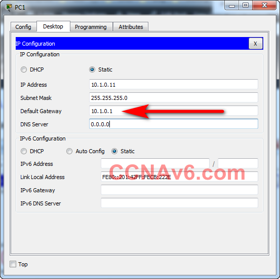
Additional Default Gateway IP: 10.1.0.1 for PCs Clnc_1 & H1-1

TYPE C- Scaling Networks - Practice Skills Assessment - EIGRP
NOTE: Use cable Console to connect PCs and Routers (Switchs)
Copy and past script for each router and switch name into User Exec mode:
Central Router:
en
conf ter
ip route 0.0.0.0 0.0.0.0 s0/1/0
ipv6 unicast-routing
ipv6 route ::/0 s0/1/0
router eigrp 99
network 192.168.100.8 0.0.0.3
network 192.168.100.20 0.0.0.3
eigrp router-id 1.1.1.1
exit
ipv6 router eigrp 99
eigrp router-id 1.1.1.1
no shutdown
exit

int s0/0/0
ipv6 eigrp 99

int s0/0/1
ipv6 eigrp 99
exit

int s0/1/0
ipv6 eigrp 99
exit

int s0/0/0
bandwidth 2000
exit

int s0/0/1
bandwidth 2000
exit

router eigrp 99
redistribute static
exit
ipv6 router eigrp 99
redistribute static
East-2 Router:
en
conf ter
ip route 0.0.0.0 0.0.0.0 s0/0/0
int g0/0
standby 1 ip 10.1.0.1
standby version 2
East Router:
en
conf ter
router eigrp 99
network 10.1.0.0 0.0.0.255
network 192.168.100.8 0.0.0.3
network 192.168.100.32 0.0.0.3
eigrp router-id 2.2.2.2
exit
ipv6 unicast-routing
ipv6 router eigrp 99
eigrp router-id 2.2.2.2
no shutdown
exit
int s0/0/1
ipv6 eigrp 99
int s0/0/0
ipv6 eigrp 99
int g0/0
ipv6 eigrp 99
exit

int s0/0/0
bandwidth 2000
exit
router eigrp 99
passive-interface g0/0
exit

int g0/0
standby 1 ip 10.1.0.1
standby 1 preempt
standby 1 priority 150
standby version 2
West Router:
en
conf ter
router eigrp 99
network 10.10.0.0 0.0.0.255
network 10.15.0.0 0.0.0.255
network 10.20.0.0 0.0.0.255
network 192.168.100.20 0.0.0.3
network 192.168.100.32 0.0.0.3
eigrp router-id 3.3.3.3
exit

ipv6 unicast-routing
ipv6 router eigrp 99
eigrp router-id 3.3.3.3
no shutdown
exit
int g0/0.10
ipv6 eigrp 99
int g0/0.15
ipv6 eigrp 99
int g0/0.20
ipv6 eigrp 99
exit

int s0/0/0
ipv6 eigrp 99
int s0/0/1
ipv6 eigrp 99
int s0/1/0
ipv6 eigrp 99
exit
int s0/0/1
bandwidth 2000
exit

router eigrp 99
passive-interface g0/0.10
passive-interface g0/0.15
passive-interface g0/0.20
exit
int g0/0
no sh
Net_1 Switch:
en
conf ter
int range f0/3-4
channel-group 1 mode active
int range f0/5-6
channel-group 2 mode active
exit
int g0/1
no shutdown

int g0/1
switchport mode trunk
switchport trunk native vlan 99
int g0/1
switchport nonegotiate

int range f0/3-4
switchport mode trunk
switchport trunk native vlan 99
int port-channel 1
switchport mode trunk
switchport trunk native vlan 99
switchport nonegotiate

int range f0/5-6
switchport mode trunk
switchport trunk native vlan 99
int port-channel 2
switchport mode trunk
switchport trunk native vlan 99
switchport nonegotiate
exit

vtp mode server
vtp domain EW-access
vtp password EWabc!
vtp version 2

spanning-tree mode rapid-pvst
spanning-tree vlan 10,15,20 priority 24576
Bldg-1 Switch:
en
conf ter
int range f0/3-4
channel-group 1 mode active
int range f0/1-2
channel-group 3 mode active
exit

int range f0/3-4
switchport mode trunk
switchport trunk native vlan 99
int port-channel 1
switchport mode trunk
switchport trunk native vlan 99
switchport nonegotiate
int range f0/1-2
switchport mode trunk
switchport trunk native vlan 99
int port-channel 3
switchport mode trunk
switchport trunk native vlan 99
switchport nonegotiate
exit

vtp mode client
vtp domain EW-access
vtp password EWabc!
vtp version 2
spanning-tree mode rapid-pvst
int range f0/10-24
spanning-tree bpduguard enable
spanning-tree portfast
Bldg-2 Switch:
en
conf ter
int range f0/5-6
channel-group 2 mode active

int range f0/1-2
channel-group 3 mode active
exit

int range f0/5-6
switchport mode trunk
switchport trunk native vlan 99

int port-channel 2
switchport mode trunk
switchport trunk native vlan 99
switchport nonegotiate
int range f0/1-2
switchport mode trunk
switchport trunk native vlan 99

int port-channel 3
switchport mode trunk
switchport trunk native vlan 99
switchport nonegotiate
exit

vtp mode client
vtp domain EW-access
vtp password EWabc!

spanning-tree mode rapid-pvst
spanning-tree vlan 10,15,20 priority 28672
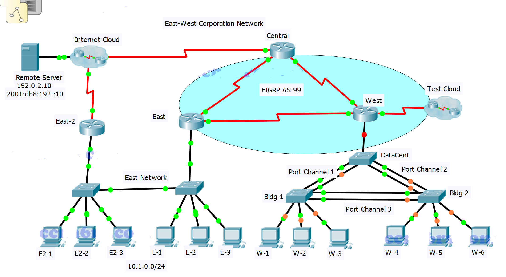
On host "E2-2", go to the "Desktop tab" >> "Command Prompt".

- Enter telnet 2001:DB8:E::1
- Authenticate your Telnet session with the password cisco.
- Move to privileged EXEC mode using the password admin.
C:\>telnet 2001:DB8:E::1
cisco // <~~~ Enter password authenticate Telnet session External>en
admin // <~~~ Enter password to move privileged EXEC mode
External#conf ter
External(config)#int g0/0
External(config-if)#no sh
Additional Default Gateway IP: 10.1.0.1 for PCs E2-1 & E1

If you only getting 75%, please temporarily uninstall Packet Tracer current version. Please download and setup “Cisco Packet Tracer 7.0” and Retake Assessment to getting 100% scores. Goodluck! :)

TYPE C arréglenlo mas que todo el Bldg-1 Switch a hubo fallas Network:R2:Ports:GigabitEthernet0/0:Hot Standby:Standby 1:Preempt —- Incorrect y quede en 93%
Plačem lebo som mal iba 97% buuuu nemám kolieska. Sudi pískaj, ani šmaľec mi nedali.
Change Net_1 switch to DataCent switch in Type C
I got 97%
HSRP Primary Configuration 0/3
Network:R2:Ports:GigabitEthernet0/0:Hot Standby:Standby 1:Priority —- Correct
Network:R2:Ports:GigabitEthernet0/0:Hot Standby:Standby 1:Preempt —- Incorrect
Network:R2:Ports:GigabitEthernet0/0:Hot Standby:Standby 1:Virtual IP —- Correct
I got 97 but I really thank you
it isn’t his fault,there wasn’t anything mentioned about ‘preempt’ command in PT Assessment requirements
I didn’t get 100% score. I only got 97%.
The result shows that ‘Network:R2:Ports:GigabitEthernet0/0:Hot Standby:Standby 1:Preempt Incorrect’.
Port-channel power,nonegotiate,dynamic mode and native vlan shud be configured for all switches..I got only 75 percent because of that..please rectify and post it
Hi, Just a quick question, Why have you advertised only two ipv4 networks on the Datacenter router, leaving out the 203.0.113.16/30 network
Because you already configure static route already, so whenever you try to reach other network (except the network you advertised) it will route to the interface that you config in static route, which mean you can access to the internet by that static route interface.