This chapter covers the following basic switching topics as a review to CCNA and serves as a teaser for topics covered later in chapter:
- Hubs and switches
- Bridges and switches
- Switches of today
- Broadcast domains
- MAC addresses
- The basic Ethernet frame format
- Basic switching function
- VLANs
- The Spanning Tree Protocol
- Trunking
- Port channels
- Multilayer switching (MLS)
Switching
LAN switching – Legacy term
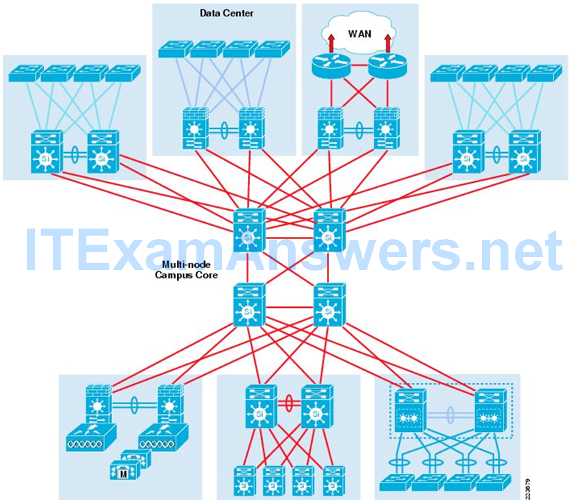
LAN Functional Areas
- Campus Networks (Focus of this book)
- L2 and L3 hierarchical design
- Data Centers (Evolving)
- Focus on applications, software defined networking (SDN)
- Technologies involved: Fabric Path, Dynamic Fabric Allocation (DFA), and Application Centric Infrastructure (ACI)
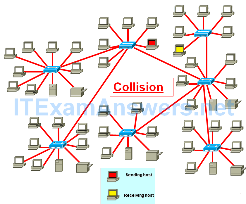
Hubs
- Legacy
- Layer 1 devices
- Multi-port repeaters
- Shared bandwidth
- Based on legacy bus topology
- CSMA/CD
- Single collision domain
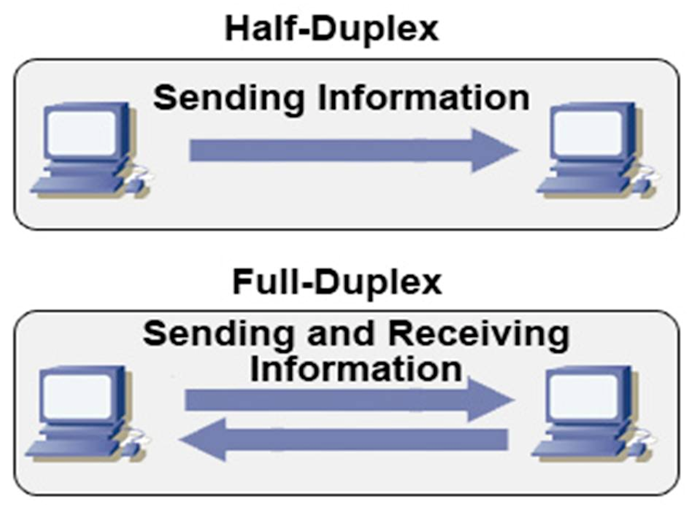
Switches
- Layer 2 devices
- Also operates at layer 1
- Full duplex
- Dedicated bandwidth
Bridges and Switches

A switch uses an algorithm from a ‘previously’ common networking device: a transparent bridge…
- Learns MAC addresses which makes forwarding decisions transparent to the host
- Can handle frames much faster than a transparent bridge because of special hardware and architecture
Switch is a device creating instantaneous connections between various ports, on a frame-by-frame basis.
Old term bridge – Transparent and translational bridges
Switches Today
Application intelligence: This helps networks recognize many types of applications and secure and prioritize those applications to provide the best user experience.
Image Unified network services: Combining the best elements of wireless and wired networking allows you to consistently connect to any resource or person with any device. 10 Gigabit Ethernet technology and Power over Ethernet (PoE) technology support new applications and devices.
Image Nonstop communications: Features such as redundant hardware, and nonstop forwarding and stateful switchover (NSF/SSO) technology support more-reliable connections.
Image Integrated security: LAN switches provide the first line of defense against internal network attacks and prevent unauthorized intrusion.
Image Operational manageability: To more easily manage the network, IT staff must be able to remotely configure and monitor network devices from a central location.
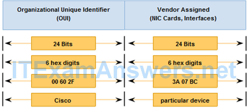
MAC Addresses
Ethernet Frame Size

Ethernet II and IEEE 802.3 standards define:
- Minimum frame size as 64 bytes
- Maximum as 1518 bytes
“collision fragment” or “runt frame” – Frame less than 64 bytes
If size of a transmitted frame is less than the minimum or greater than the maximum, the receiving device drops the frame
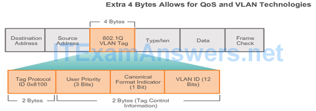
In 1998, IEEE 802.3ac standard extended the maximum allowable frame size to 1522 bytes.
Increased to accommodate a technology called Virtual Local Area Network (VLAN).
VLANs will be presented in a later course.
5.2.1.4 – MAC Address Tables on Connected Switches
For every Ethernet frame that enters a port, the switch will:
Step 1: Learn (Building the MAC address table)
Switch learns by examining the source MAC address
- If not in MAC address table, then add it along with incoming port number
- If in MAC address table, reset 5 minute timer
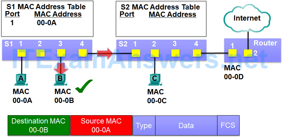
PC-A sends a frame to PC-B
The fame is received by switch S1
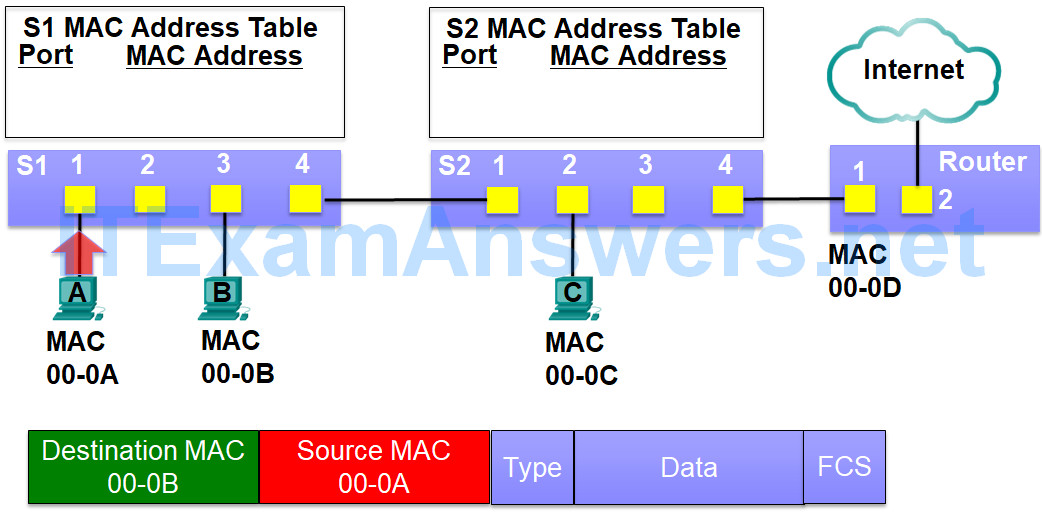
Switch S1 sees if it has something to learn by examining the source MAC address
The source MAC address is not in its MAC address table
S1 adds the source MAC address 00-0A and the incoming port 1 to its MAC address table
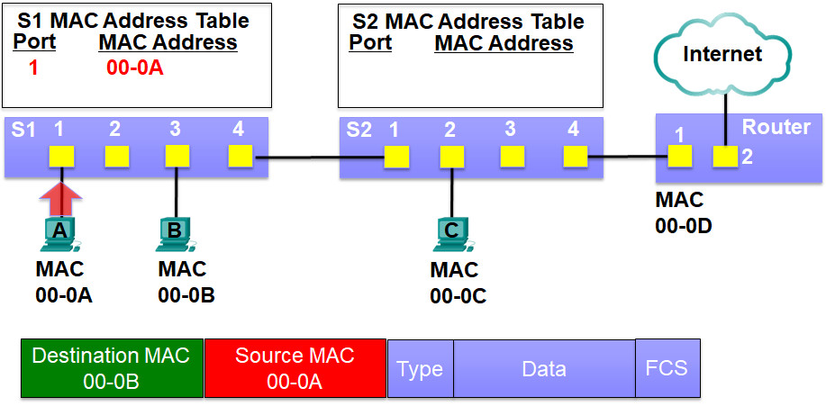
Step 2: Forwarding the frame (Using the MAC address table)
Switch forwards by examining the destination MAC address
- If broadcast/multicast MAC address, flood out all ports except the port it came in on
- If unicast MAC address is in MAC address table, send it out only that port
- If unicast MAC address is not in in MAC address table, flood out all ports except the port it came in on (unknown unicast)
S1 can now forward the frame by examining the destination MAC address
The destination MAC address 00-0B is not in its MAC address table, so it floods it out all ports
This is known as an unknown unicast
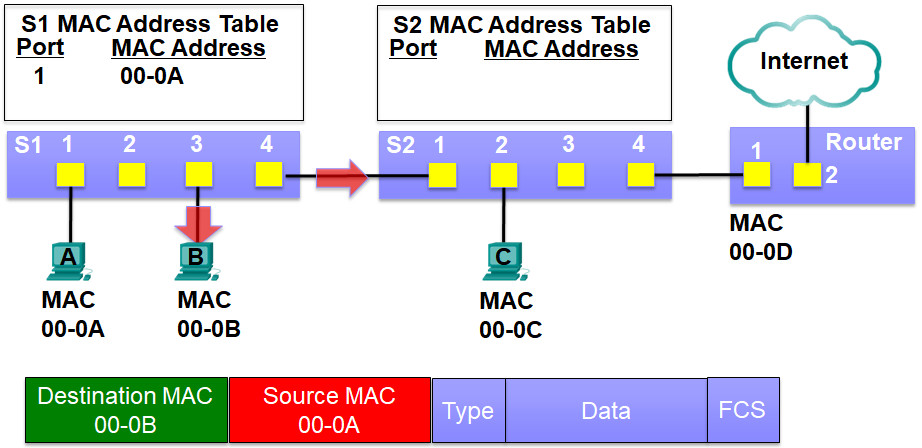
PC-B’s NIC receives the frame.
After comparing the destination MAC address of 00-0B to it own NIC’s MAC address it realizes they are the same and copies in the rest of the frame.
For every Ethernet frame that enters a port, the switch will:
Step 1: Learn (Building the MAC address table)
Switch learns by examining the source MAC address
- If not in MAC address table, then add it along with incoming port number
- If in MAC address table, reset 5 minute timer
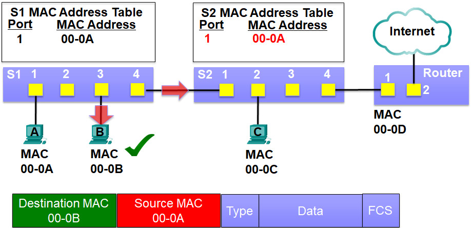
The frame is also flooded out S1’s port 4 which is connected to switch S2
S2 receives the frame and examines the source MAC address
Since this is new information, S2 add the source MAC address 00-0A and the incoming port number 1 to its MAC address table
Step 2: Forwarding the frame (Using the MAC address table)
Switch forwards by examining the destination MAC address
- If broadcast/multicast MAC address, flood out all ports except the port it came in on
- If unicast MAC address is in MAC address table, send it out only that port
- If unicast MAC address is not in in MAC address table, flood out all ports except the port it came in on (unknown unicast)
S2 can now forward the frame by examining the destination MAC address
The destination MAC address 00-0B is not in its MAC address table, so it floods it out all ports
Again, this is known as an unknown unicast
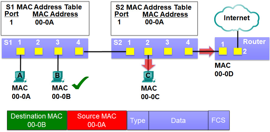
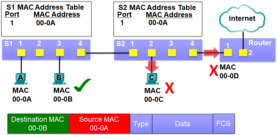
Both PC-C’s NIC and the Router’s NIC receives the frame.
Since their MAC addresses do not match the destination MAC address they drop the rest of the frame
For every Ethernet frame that enters a port, the switch will:
Step 1: Learn (Building the MAC address table)
Switch learns by examining the source MAC address
- If not in MAC address table, then add it along with incoming port number
- If in MAC address table, reset 5 minute timer
PC-B now sends the frame to PC-A
The frame is received by switch S1
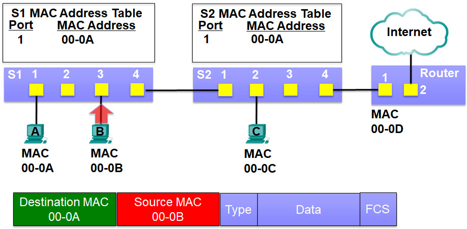
Switch S1 sees if it has something to learn by examining the source MAC address
The source MAC address is not in its MAC address table
S1 adds the source MAC address 00-0B and the incoming port 3 to its MAC address table
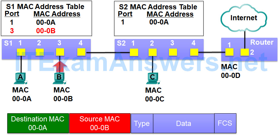
Step 2: Forwarding the frame (Using the MAC address table)
Switch forwards by examining the destination MAC address
- If broadcast/multicast MAC address, flood out all ports except the port it came in on
- If unicast MAC address is in MAC address table, send it out only that port
- If unicast MAC address is not in in MAC address table, flood out all ports except the port it came in on (unknown unicast)
S1 can now forward the frame by examining the destination MAC address
The destination MAC address 00-0A is in its MAC address table, so it filters the frame by sending it out only port 1
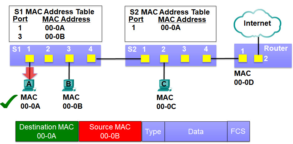
5.2.1.5 – Sending a Frame to the Default Gateway
Destination IP address is on a remote network.
PC-A will send the Ethernet frame to the MAC address of the default gateway
For every Ethernet frame that enters a port, the switch will:
Step 1: Learn (Building the MAC address table)
Switch learns by examining the source MAC address
- If not in MAC address table, then add it along with incoming port number
- If in MAC address table, reset 5 minute timer
Switch S1 sees if it has something to learn by examining the source MAC address
The source MAC address is in its MAC address table, so it has nothing new to learn
S1 refreshes the 5 minute refresh timer for this entry
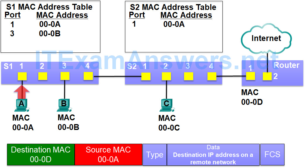
Step 2: Forwarding the frame (Using the MAC address table)
Switch forwards by examining the destination MAC address
- If broadcast/multicast MAC address, flood out all ports except the port it came in on
- If unicast MAC address is in MAC address table, send it out only that port
- If unicast MAC address is not in in MAC address table, flood out all ports except the port it came in on (unknown unicast)
S1 can now forward the frame by examining the destination MAC address
The destination MAC address 00-0D is not in its MAC address table, so it floods it out all ports
This is known as an unknown unicast

PC-B’s NIC receives the frame and ignores the rest of the frame after determining that the destination MAC address of 00-0D does not match it’s own MAC address of 00-0B
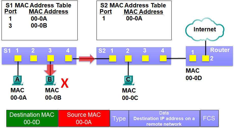
For every Ethernet frame that enters a port, the switch will:
Step 1: Learn (Building the MAC address table)
Switch learns by examining the source MAC address
If not in MAC address table, then add it along with incoming port number
If in MAC address table, reset 5 minute timer
The frame is also flooded out S1’s port 4 which is connected to switch S2
S2 receives the frame and examines the source MAC address
The source MAC address of 00-0A and port 1 is in its MAC address table, so it has nothing new to learn
S2 refreshes the 5 minute refresh timer for this entry
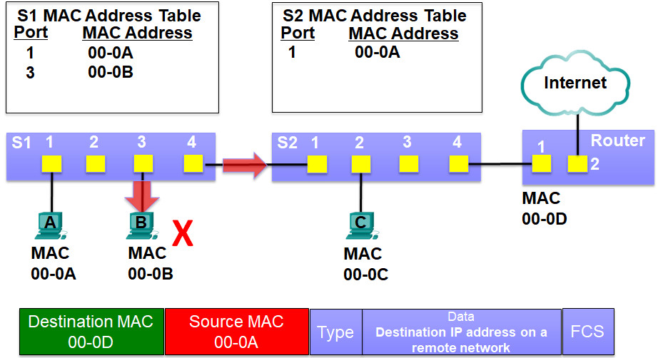
Step 2: Forwarding the frame (Using the MAC address table)
Switch forwards by examining the destination MAC address
If broadcast/multicast MAC address, flood out all ports except the port it came in on
If unicast MAC address is in MAC address table, send it out only that port
If unicast MAC address is not in in MAC address table, flood out all ports except the port it came in on (unknown unicast)
S2 can now forward the frame by examining the destination MAC address
The destination MAC address 00-0D is not in its MAC address table, so it floods it out all ports
Again, this is known as an unknown unicast
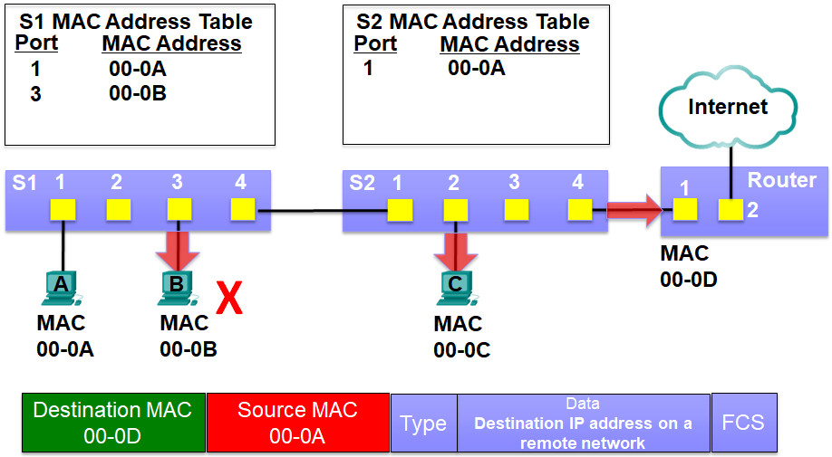
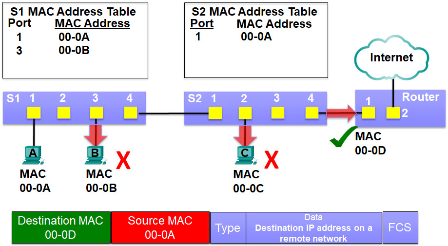
PC-C’s NIC and the Router’s NIC receives the frame.
PC-C’s MAC addresses does not match the destination MAC address so it drops the rest of the frame
The router’s MAC address does match the destination MAC address so it copies in the rest of the frame
The router will de-encapsulate the data from the Ethernet frame and process the Layer 3 PDU, the IP packet, for routing.
For every Ethernet frame that enters a port, the switch will:
Step 1: Learn (Building the MAC address table)
Switch learns by examining the source MAC address
If not in MAC address table, then add it along with incoming port number
If in MAC address table, reset 5 minute timer
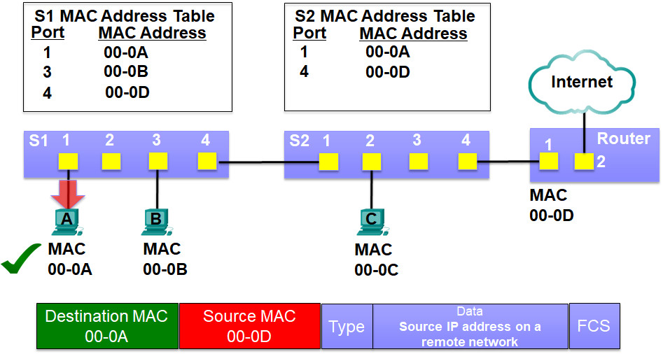
The router now sends the frame to PC-A
The frame is received by switch S2
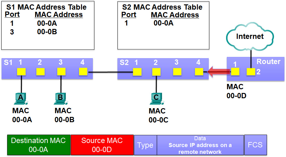
Switch S2 sees if it has something to learn by examining the source MAC address
The source MAC address is not in its MAC address table
S2 adds the source MAC address 00-0D and the incoming port 4 to its MAC address table
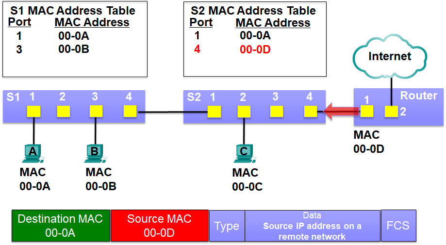
Step 2: Forwarding the frame (Using the MAC address table)
Switch forwards by examining the destination MAC address
If broadcast/multicast MAC address, flood out all ports except the port it came in on
If unicast MAC address is in MAC address table, send it out only that port
If unicast MAC address is not in in MAC address table, flood out all ports except the port it came in on (unknown unicast)
S2 can now forward the frame by examining the destination MAC address
The destination MAC address 00-0A is in its MAC address table, so it filters the frame by sending it out only port 1
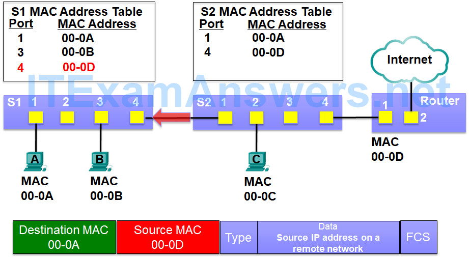
For every Ethernet frame that enters a port, the switch will:
Step 1: Learn (Building the MAC address table)
Switch learns by examining the source MAC address
If not in MAC address table, then add it along with incoming port number
If in MAC address table, reset 5 minute timer
Switch S1 sees if it has something to learn by examining the source MAC address
The source MAC address is in its MAC address table, so it has nothing new to learn
S1 refreshes the 5 minute refresh timer for this entry
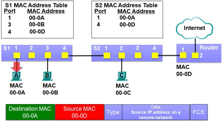
Step 2: Forwarding the frame (Using the MAC address table)
Switch forwards by examining the destination MAC address
If broadcast/multicast MAC address, flood out all ports except the port it came in on
If unicast MAC address is in MAC address table, send it out only that port
If unicast MAC address is not in in MAC address table, flood out all ports except the port it came in on (unknown unicast)
S1 can now forward the frame by examining the destination MAC address
The destination MAC address 00-0A is in its MAC address table, so it filters the frame by sending it out only port 1
5.3.2.3 – ARP Operation – ARP Request
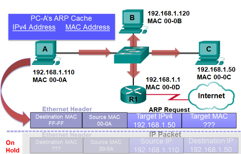
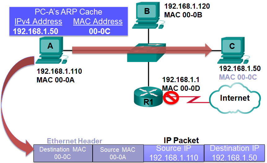
PCA at 192.168.1.110 has an IPv4 packet to send to 192.168.1.50
Comparing its IPv4 address with the destination IPv4 address, PCA determines this device is on the same IP network
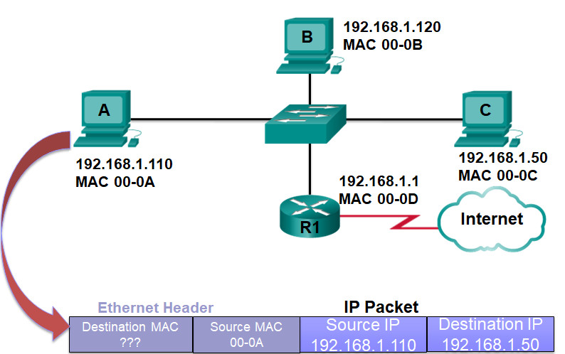
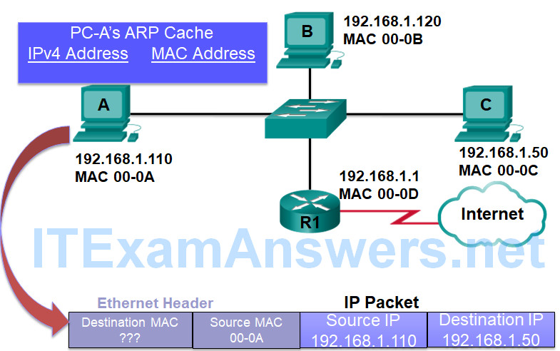
PCA checks its ARP table for 192.168.1.50 but no match
PCA puts the IPv4 packet on hold and creates an ARP Request with
Target IPv4 = 192.168.1.50
Target MAC – unknown
Source MAC 00-A
Destination MAC = broadcast
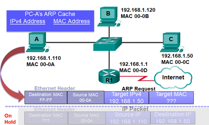
PCA sends the ARP request which is received by the switch
Because the destination MAC is a broadcast the switch sends it out all ports but the incoming port
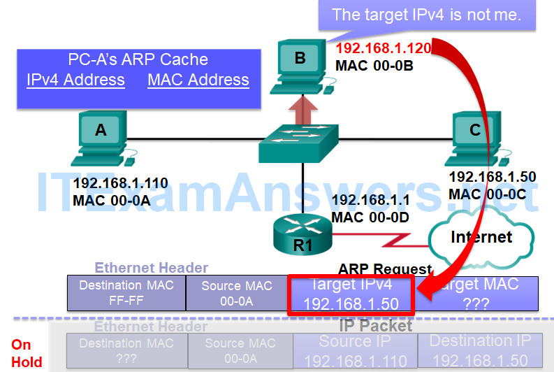
PCB compares the target IPv4 address to its own MAC address and because it is not a match ignores the ARP request
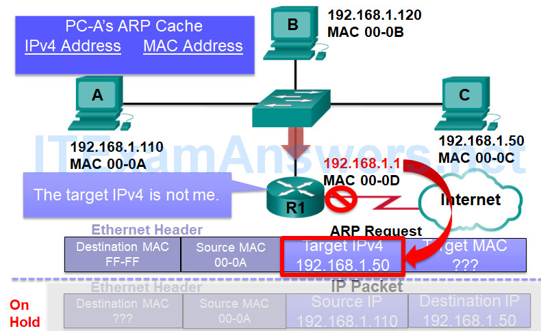
Router R1 compares the target IPv4 address to its own MAC address and because it is not a match ignores the ARP request.
Routers do not forward broadcasts.
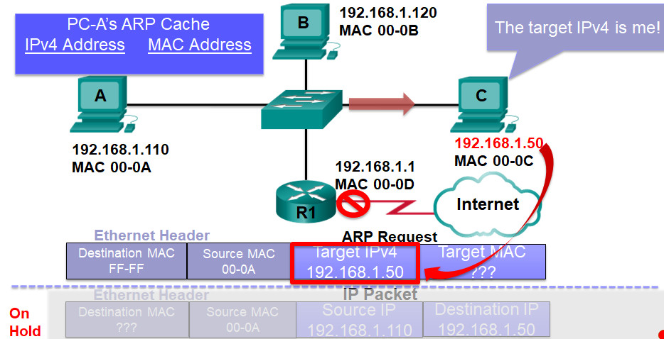
The target address in the ARP request matches PCC’s IPv4 address
5.3.2.4 – ARP Operation – ARP Reply
The target address in the ARP request matches PCC’s IPv4 address

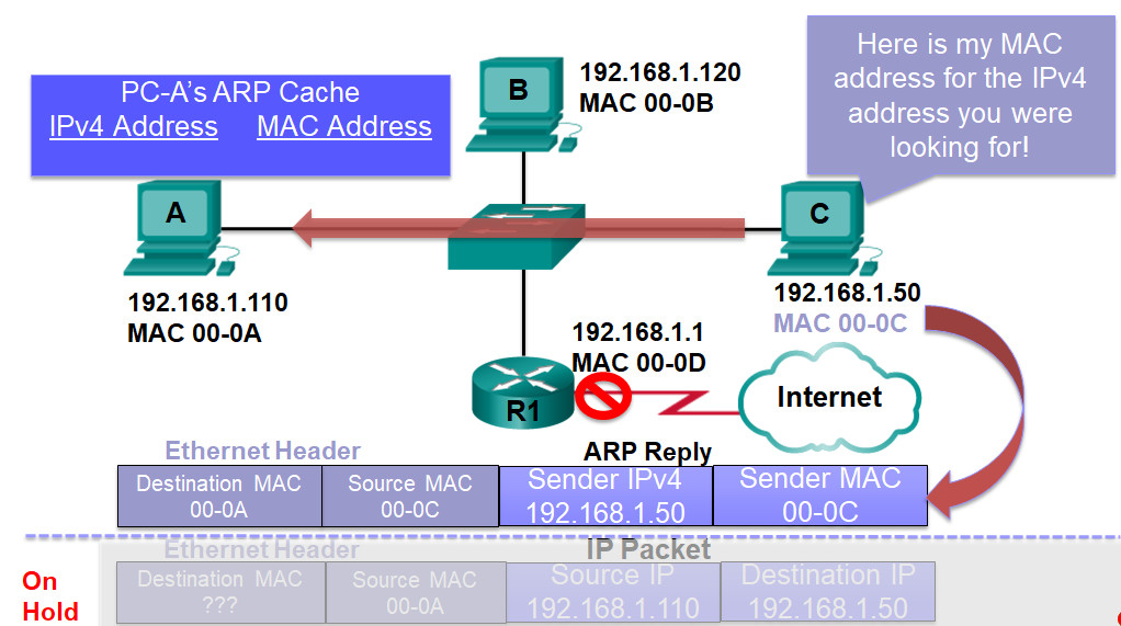
PCC sends an ARP reply to the sender of the ARP request
This is a unicast
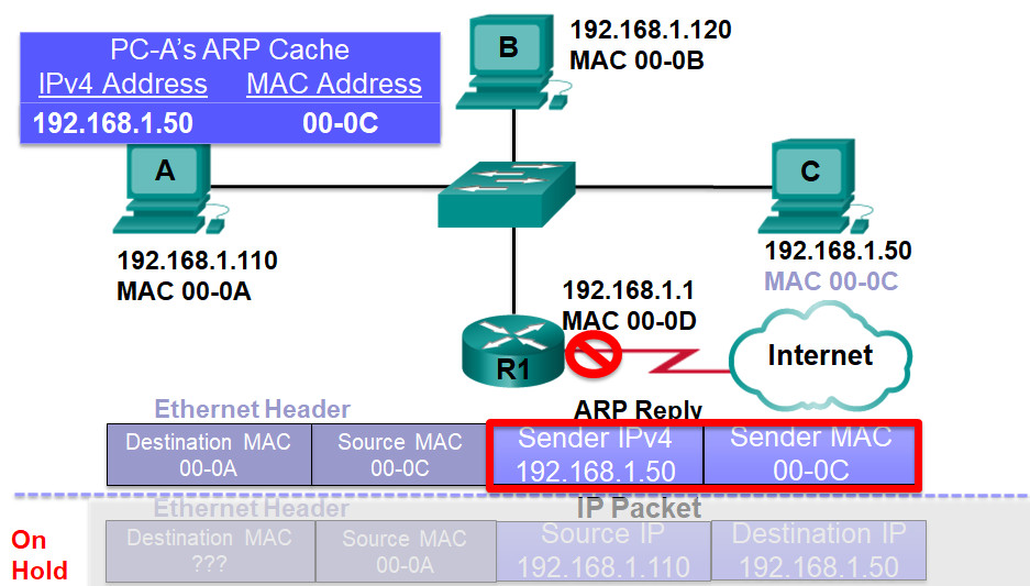
Sender IPv4 = 192.168.1.50
Sender MAC – 00-0C
Source MAC 00-0C
Destination MAC = 00-0A
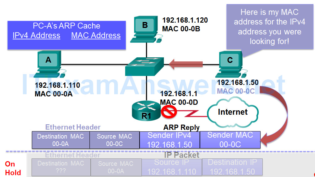
PCA receives the ARP reply
PCC Adds the sender’s IPv4 address and MAC address to its ARP table
PCC takes the IPv4 packet off hold
PCC uses the MAC address for the destination MAC address
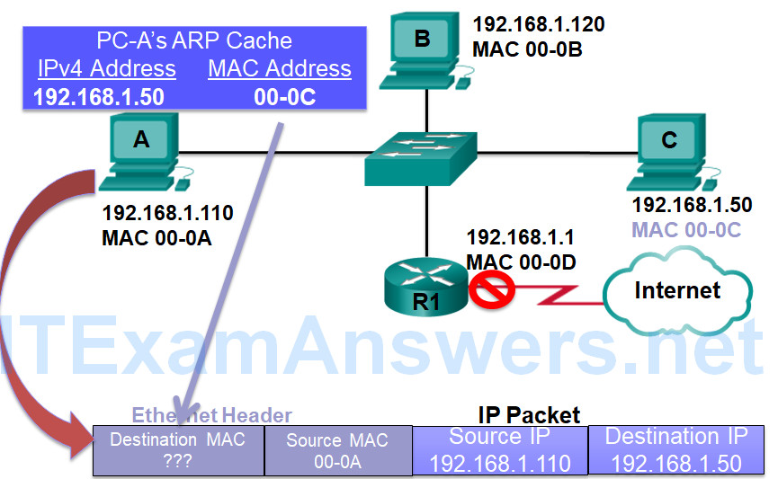
PCA now sends this Ethernet frame with the encapsulated IPv4 packet out its Ethernet NIC
5.3.2.5 – ARP Role in Remote Communication
PCA at 192.168.1.110 has an IPv4 packet to send to 10.1.1.10
Comparing its IPv4 address with the destination IPv4 address, PCA determines this device is on a different IP network
PCA must sent this packet to its default gateway 192.168.1.1
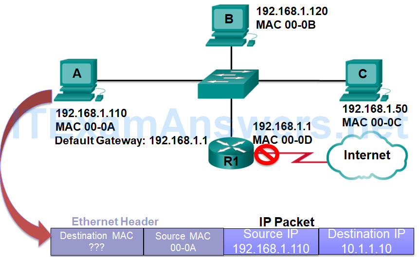
PCA checks its ARP table for 192.168.1.1 but no match
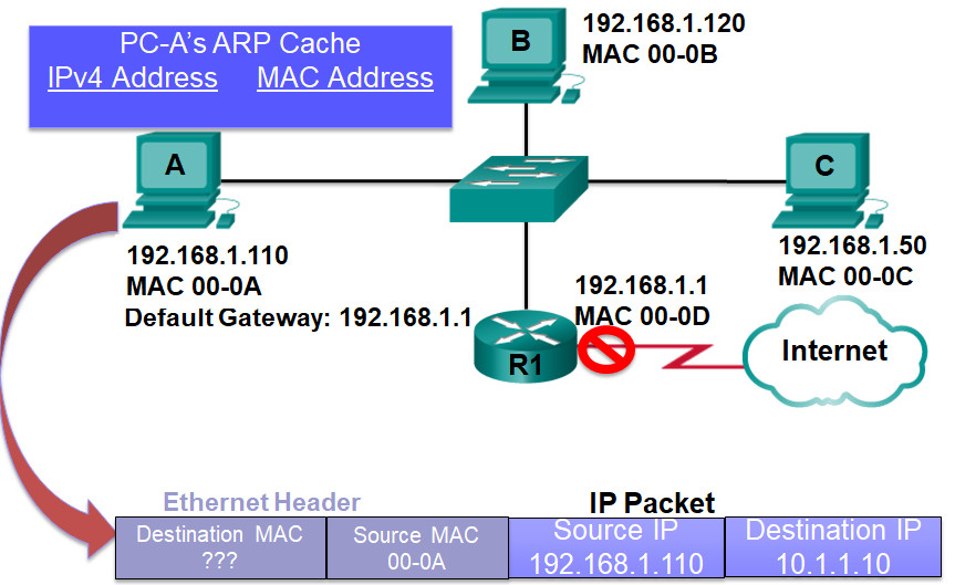
PCA puts the IPv4 packet on hold and creates an ARP Request with
Target IPv4 = 192.168.1.1
Target MAC – unknown
Source MAC 00-A
Destination MAC = broadcast
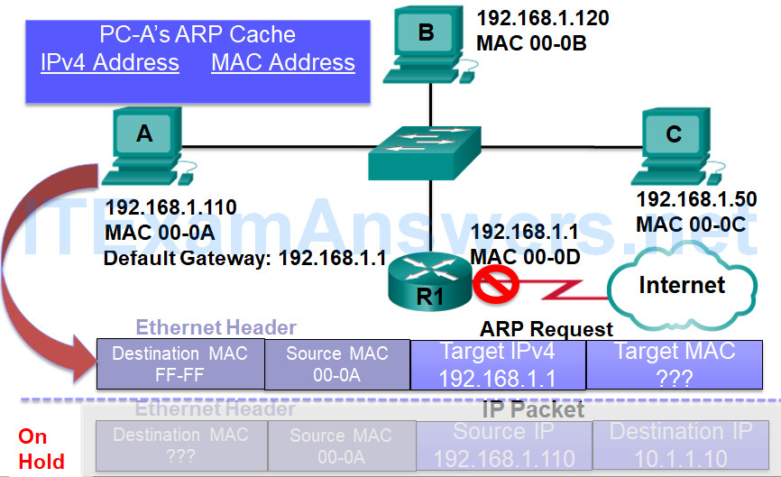
PCA sends the ARP request which is received by the switch
Because the destination MAC is a broadcast the switch sends it out all ports but the incoming port
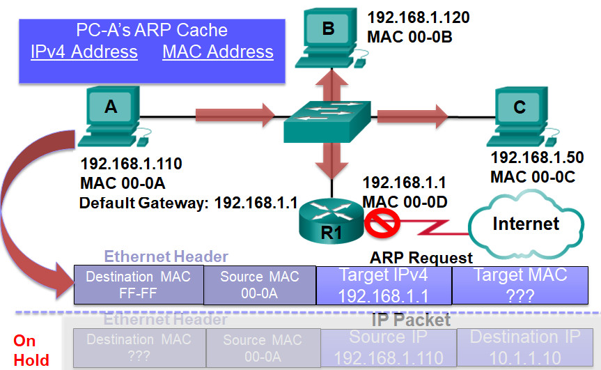
PCB compares the target IPv4 address to its own MAC address and because it is not a match ignores the ARP request
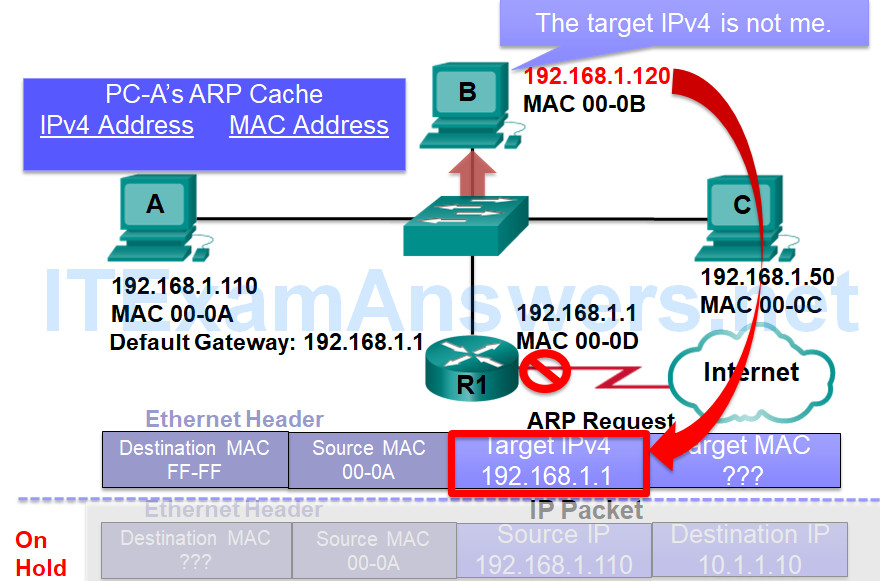
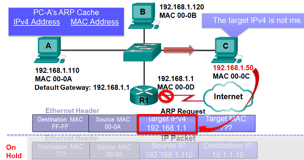
PCC compares the target IPv4 address to its own MAC address and because it is not a match ignores the ARP request
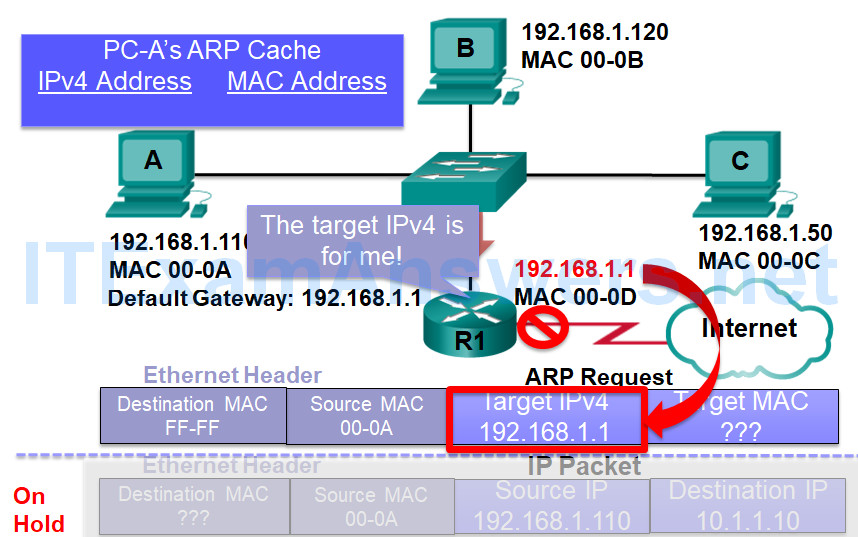
The target address in the ARP request matches the router’s the IPv4 address on its G0/0 interface
PCC sends an ARP reply to the sender of the ARP request
This is a unicast
Sender IPv4 = 192.168.1.1
Sender MAC – 00-0D
Source MAC 00-0D
Destination MAC = 00-0A
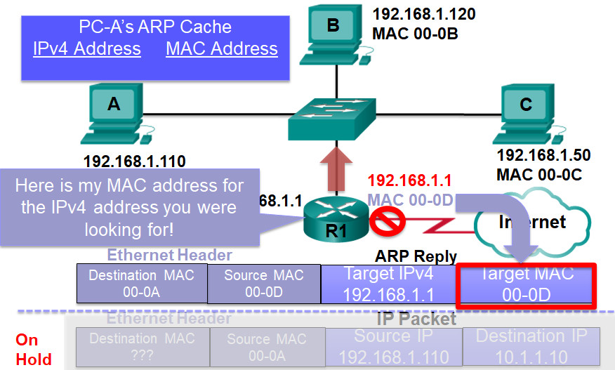
PCA receives the ARP reply
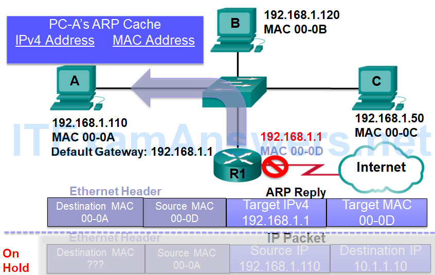
PCC Adds the sender’s IPv4 address and MAC address to its ARP table
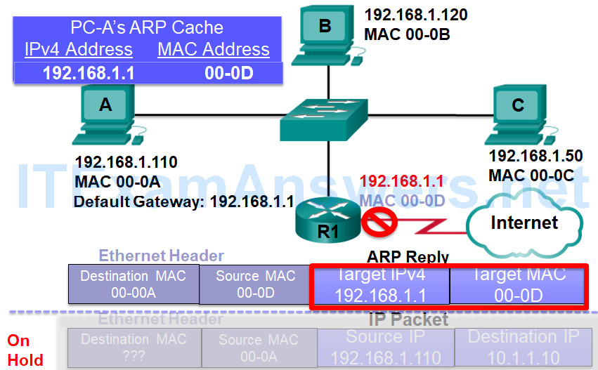
PCC takes the IPv4 packet off hold
PCC uses the MAC address for the destination MAC address
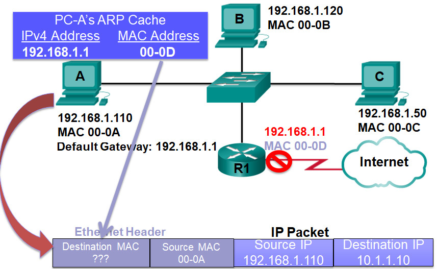
PCA now sends this Ethernet frame with the encapsulated IPv4 packet out its Ethernet NIC towards the default gateway
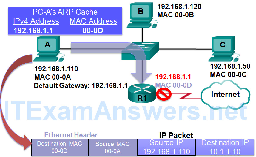
It’s all about the IPv4 Address
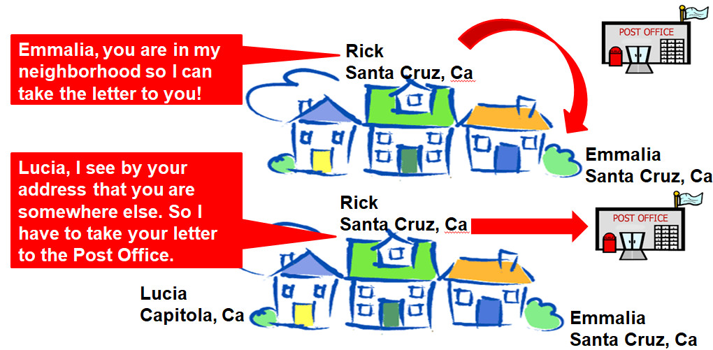
Even if two houses are on the same street, you only know the address so must take it to the local post office
Understanding IPv4 communications
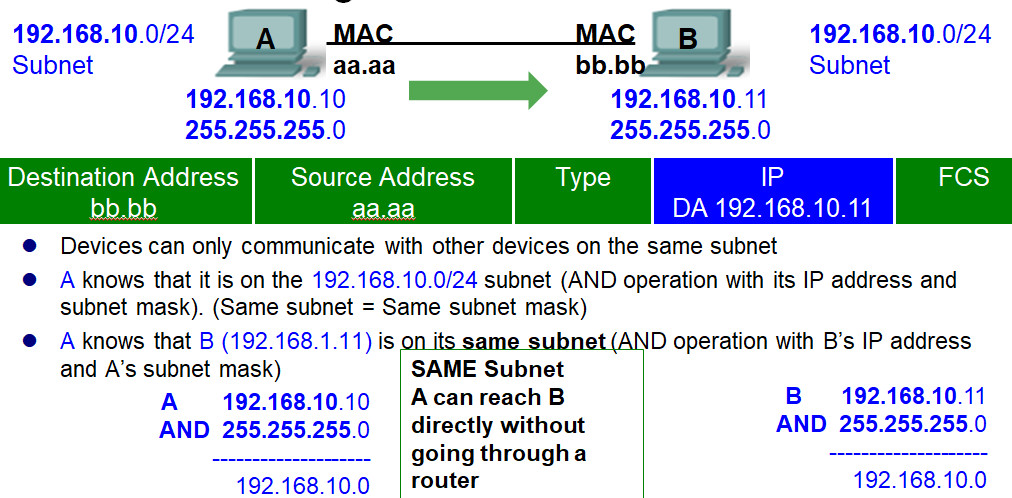
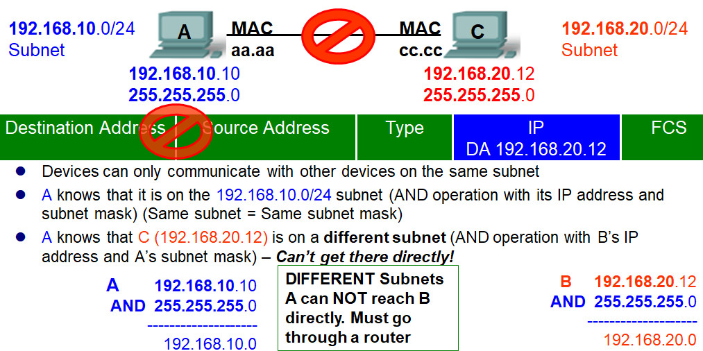
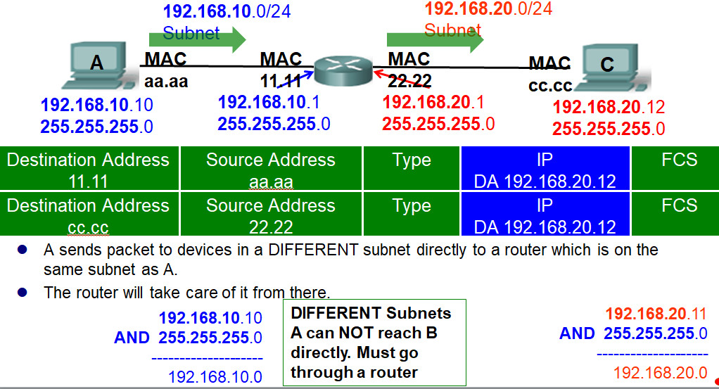
Understanding IPv4 communications
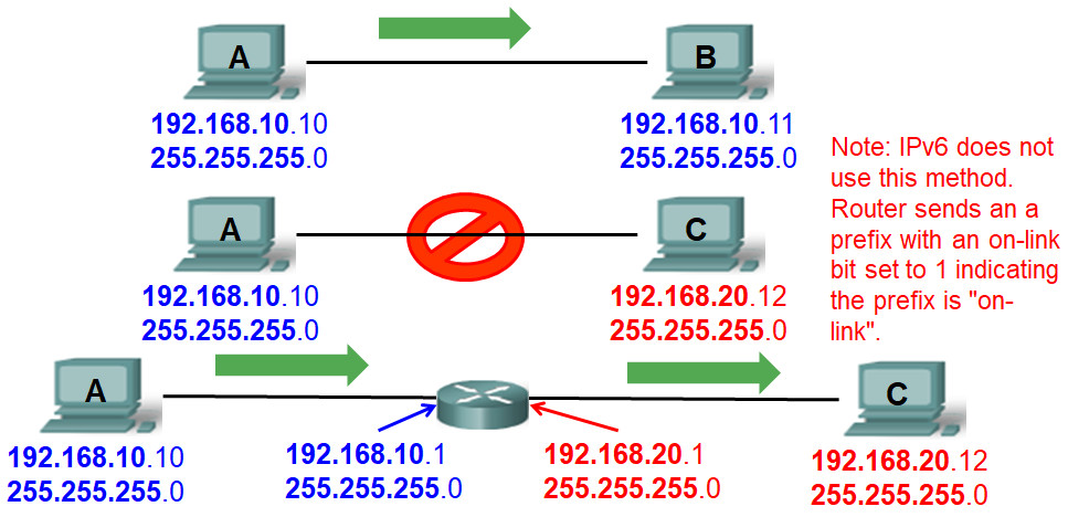
- Devices can only communicate with other devices on the same subnet
- Otherwise, they must go through a router, that is on its same subnet
VLANs
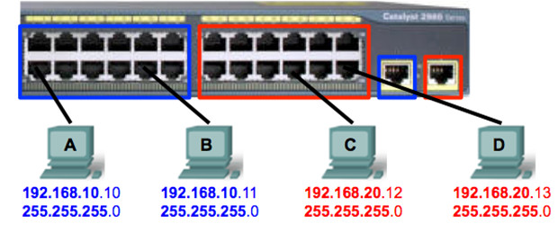
- Switches decide on a frame-by-frame which ports exchange data.
- Switches designed with a logic that allow ports to be logically grouped
- This ports groupings are called Virtual LANs
- VLANs are also determine the boundaries of the broadcast communications.
- Need a router (or multilayer switch) to route between VLANs
No VLANs Needed
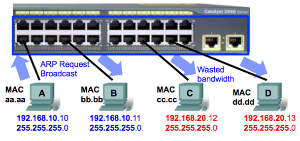
- VLANs are not required to have multiple subnets on a single switch.
- VLANs provide broadcast segmentation and a layer of security between VLANs
VLAN Trunks

- A port on a switch normally belongs to only one VLAN
- A trunk port is a port that can be configured to send/receive traffic for multiple VLANs.
- Trunking is a mechanism that is most often used to allow multiple VLANs to function independently across multiple switches.
- Routers and servers can use trunking, as well.
- A point-to-point link that carries more than one VLAN.
- It accomplishes this when it attaches VLAN information to each frame, a process called tagging the frame.
- Extend VLANs across multiple switches
- Cisco supports 802.1Q standard
- Some older switches support legacy Cisco ISL
Spanning Tree Protocol (STP)
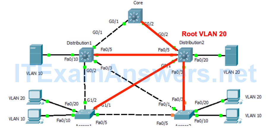
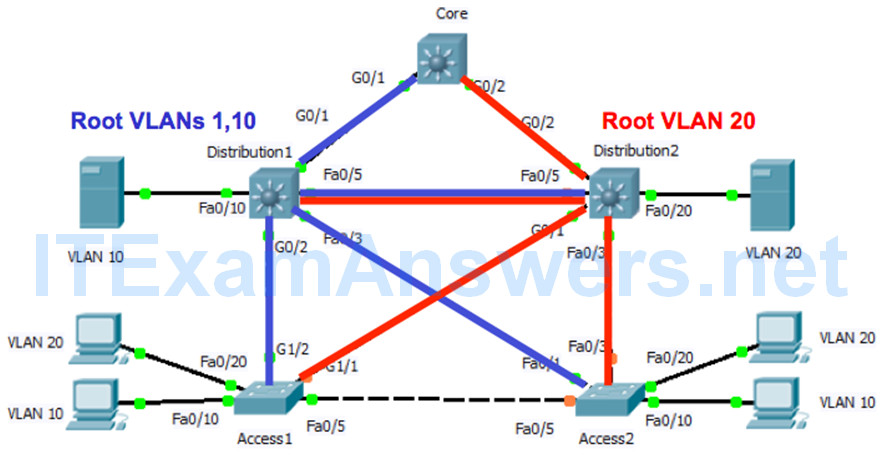
- The switch forwarding algorithm floods unknown and broadcast frames out of all ports in the same VLAN as the received frame
- If the networking devices connected together in a physical loop, flooded frames are passed from switch-to-switch forever.
- There is a benefit to a physical loop in a network as it can provide redundancy.
- Spanning-Tree protocol identify and temporarily and dynamically block the physical loops in a network.
Port Channel

- Port channels (EtherChannels) – Technique used to group multiple ports to work as one unit.
- Makes use of redundant links to provide additional bandwidth.
- Port channels distribute traffic across all the links and provide redundancy if one or more links fail.
- Normally, spanning tree would block all of these parallel connections between devices because they are loops.
- But port channels run underneath spanning tree, so that spanning tree thinks all the ports within a given port channel are only a single port.
Multilayer Switching
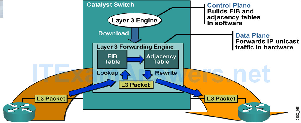
- Multilayer switching (MLS) is the ability of a switch to forward frames based on information in the Layer 3 and sometimes Layer 4 header
- The most important aspect to MLS is recognizing that switches can route or switch frames at wire-rate speeds using specialized hardware.
- This effectively bundles the routing function into the switch and is specifically useful for routing between VLANs in the core of the network.
