Tag: Network Topology
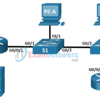
1.2.7 Packet Tracer - Connect a Network Based on a Network Diagram Objectives In this activity, you will complete a physical topology based on a provided network diagram. Network Diagram Instructions Network diagrams are essential to visualizing how devices are connected and work together. Diagrams can act as …
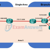
2.7.3 Packet Tracer - Multiarea OSPF Exploration - Physical Mode (Part 1) Answers Objectives Part 1: Evaluate Network Operation of Single-Area OSPF Part 2: Evaluate Network Operation of Multiarea OSPF Part 3: Configure a New Area and Attach to Area 0 Through the Internet Topology Background / Scenario …
9.3.4 Packet Tracer - Data Center Exploration - Physical Mode Answers Objectives Part 1: Explore the Characteristics of a Small Data Center Part 2: Create a Plan for Expanding the Current Data Center Part 3: Configure the Data Center Devices to Expand the Capacity Background / Scenario Data …
1.0.5 Packet Tracer - Logical and Physical Mode Exploration Answers Objectives Part 1: Investigate the Bottom Toolbar Part 2: Investigate Devices in a Wiring Closet Part 3: Connect End Devices to Networking Devices Part 4: Install a Backup Router Part 5: Configure a Hostname Part 6: Explore the …
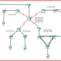
12.6.1 Packet Tracer - Troubleshooting Challenge - Document the Network (Instructor Version) Instructor Note: Red font color or gray highlights indicate text that appears in the instructor copy only. Addressing Table Device Interface Device Type (router, switch, host) IP Address Subnet Mask Default Gateway PC1 NIC Host 192.168.1.153 …
10.2.6 Packet Tracer - Use LLDP to Map a Network (Instructor Version) Addressing Table Device Interface IP Address Subnet Mask Local Interface and Connected Neighbor Edge G0/0 192.168.1.1 255.255.255.0 G0/1 - S1 S0/0/0 209.165.200.5 255.255.255.252 S0/0/0 - ISP S1 SVI 192.168.1.2 255.255.255.0 RBO-Edge G0/0 209.165.200.10 255.255.255.252 G0/0 - …
10.1.5 Packet Tracer - Use CDP to Map a Network (Instructor Version) Instructor Note: Red font color or gray highlights indicate text that appears in the instructor copy only. Addressing Table Device Interface IP Address Subnet Mask Local Interface and Connected Neighbor Edge1 G0/0 192.168.1.1 255.255.255.0 G0/1 - …
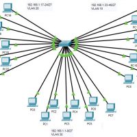
3.1.4 Packet Tracer - Who Hears the Broadcast? Answers Topology Objectives Part 1: Observe Broadcast Traffic in a VLAN Implementation Part 2: Complete Review Questions Scenario In this activity, a 24-port Catalyst 2960 switch is fully populated. All ports are in use. You will observe broadcast traffic in …
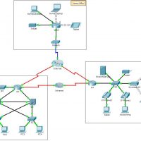
1.5.5 Packet Tracer - Network Representation (Instructor Version – Optional Packet Tracer) 1.5.7 Packet Tracer - Network Representation Instructor Note: Red font color or green highlights indicate text that appears in the instructor copy only. Topology Objectives The network model in this activity incorporates many of the technologies …